Structural Design I Course Code CIVL 312 Reinforced


- Slides: 20
Structural Design I Course Code: CIVL 312 Reinforced concrete column By : Dr. Aeid A. Abdulrazeg
Column Sections Subjected to Axial Load and Biaxial Bending • The columns are subjected to an axial and bending moment in both x and y directions.
Failure surface method • At an axial load N the section can support uniaxial moments Mux and Muy. If it is subjected to moments Mx and My simultaneously which are such as to cause failure, then the failure point is at P which lies on the curve of intersection APB of the failure surface and the horizontal plane through N.
Failure surface method
Failure surface method
Failure surface method • This curve is defined by the expression: • • • N axial load on the section subjected to biaxial bending Nuz capacity of the section under axial load only, 0. 45 fcu. Ac+0. 75 fy. As′ Ac area of concrete As′ area of longitudinal steel Mx moment about the XX axis My moment about the YY axis Mux moment capacity for bending about the XX axis only when the axial load is N Muy moment capacity for bending about the YY axis only when the axial load is N
Failure surface method • The shape of the curve APB depends on the value of N/Nuz. • It is an ellipse when αn=2 and a straight line when αn=1. This is the expression given in
Example: Column section subjected to axial load and biaxial bending • Check that the section shown in Figure can resist the following actions: • ultimate axial load N=950 k. N • ultimate moment Mx about XX axis=95 k. N m • ultimate moment My about YY axis=65 k. N m • The materials are grade 30 concrete and grade 460 reinforcement. • The capacity Nuz of the section under pure axial load is
Example: Column section subjected to axial load and biaxial bending • The capacity Nuz of the section under pure axial load is
Example: Column section subjected to axial load and biaxial bending • The bending about XX axis is • Use BS 8110: Part 3, Chart 28:
• The bending about YY axis is • Use BS 8110: Part 3, Chart 28:
Example: Column section subjected to axial load and biaxial bending • Substitute into the interaction expression and obtain: • The section is satisfactory
Method given in BS 8110 • A direct design method is given in BS 8110: Part 1, clause 3. 8. 4. 5. • The method is derived from the failure surface theory and consists in designing a section subjected to biaxial bending for an increased moment about one axis. • The main design axis depends on the relative values of the moments and the column section dimensions. The amount of increase depends on the ratio of the axial load to the capacity under axial load only.
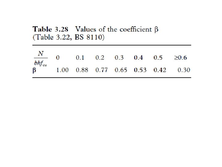
Method given in BS 8110 • The code procedure is set out. • Define the following terms: Mx design ultimate moment about the XX axis Mx′ effective uniaxial design moment about the XX axis My design ultimate moment about the YY axis My′ effective uniaxial design moment about the YY axis h overall depth perpendicular to the XX axis h′ effective depth perpendicular to the XX axis b overall width perpendicular to the YY axis b′ effective width perpendicular to the YY axis
Method given in BS 8110
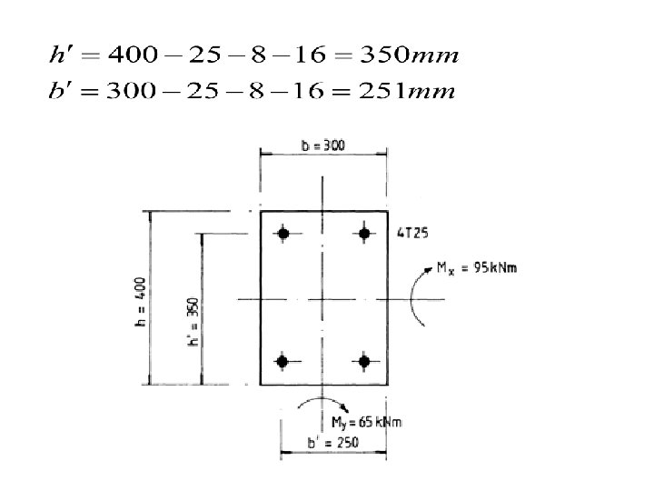
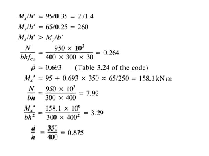
• • • Example : Column section subjected to axial load and biaxial bending—BS 8110 method Check that the section shown in Figure can resist the following actions: ultimate axial load N=950 k. N ultimate moment Mx about XX axis=95 k. N m ultimate moment My about YY axis=65 k. N m The materials are grade 30 concrete and grade 460 reinforcement. Assume the cover is 25 mm, links are 8 mm in diameter and main bars are 32 mm in diameter.
• Use BS 8110: part 3, Chart 28, where d/h = 0. 85 • Provide 4 T 25 bars to give an area of 1963 mm 2