STRUCTURAL ANALYSIS AND DESIGN OF HUSAM QURESH BUILDING

STRUCTURAL ANALYSIS AND DESIGN OF HUSAM QURESH BUILDING By: Qais Ghannam Aws Radwan Amr Abed Supervisor: Eng. Hind Tbaileh

INTRDUCTION • • Project description Materials Soil investigation Codes and standard Seismicity of Site and Structure Loads Load combination

PROJECT DESCRIPTION ▪ This project is about a Private commercial multi-storey building in Nablus city, rafedia region, and this building is under construction. ▪ The building is over looking on two streets, a major street in the south and a Minor street on the east, and its away 3 m from the major street, and 2 m from the minor one.

▪ The building is about ten floors, three of them are underground floors, the lowest two floors (B 3 and B 2) will be Garages, the first underground storey (B 1) will be depository, the ground floor will be Stores, the ground floor has an attic 3 meters in height, the first and second floors will be Wedding Hall and museum respectively, and the remaining floors designed to be offices.

▪ Floor B 3 B 2 B 1 G attic 1 -6

▪ The height and elevation of each floor :

MATERIALS ▪ Concrete ▪

▪ Steel

▪ Non-structural materials

SOIL INVESTIGATION ▪

CODES AND STANDARD ▪ ACI 318 -14 ▪ ASCE 7 -10 ▪ IBC 2012

SEISMICITY OF SITE AND STRUCTURE

• Z for Nablus = 0. 2 • SS = 2. 5 × Z = 2. 5 × 0. 2 = 0. 5 • S 1 = 1. 25 × Z =1. 25 × 0. 2 = 0. 25
")
Site class Stiff Soil (C)

Site Coefficient Fa = 1. 2
 = 1. 55")
Site Coefficient Fv (by interpolation) = 1. 55

• SMS = Fa × SS = 0. 6 • SM 1 = Fv × S 1 = 0. 3875 • SDS = SS = 0. 6 • SD 1 = S 1 = 0. 3875

Risk Category = II

Seismic design category =D

LOADS ▪ Gravity Loads

▪ Lateral Load • The method used in determination the effect of earthquake load is modal response method. • Verified by ELF

LOAD COMBINATION Ultimate Load Combinations: • • • 1. 4 D 1. 2 D +1. 6 L 1. 32 D +L +1. 3 EQx +0. 39 EQy 1. 32 D +L +1. 3 EQy +0. 39 EQx 0. 78 D +1. 3 EQx +0. 39 EQy 0. 78 D +1. 3 EQy +0. 39 EQx

▪ Service Load Combinations: • D+L • 1. 084 D+0. 91 EQx+0. 273 EQy • 1. 084 D+0. 91 EQy+0. 273 EQx • 1. 063 D +0. 75 L +0. 683 EQx +0. 205 EQy • 1. 063 D +0. 75 L +0. 683 EQy +0. 205 EQx • 0. 516 D+0. 91 EQx+0. 273 EQy • 0. 516 D+0. 91 EQy+0. 273 EQx

PRELIMINARY DIMENTIONS ▪ Slabs ▪ Beams ▪ Columns
 two way solid")
SLAB THICKNESS We have a two way system that used: 1) two way solid slab : it used for B 3 slab. 2) two way U-boot slab: it used for all floors except B 3 slab.
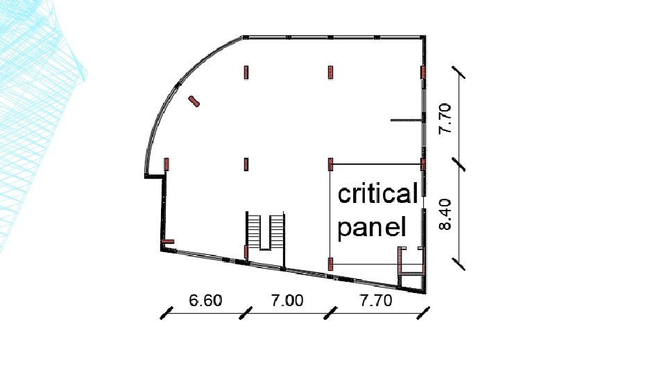
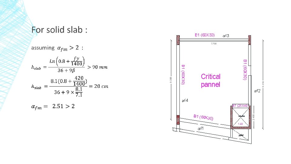

For U-BOOT SLAB : U-boot dimensions : Height = 20 cm Width = length = 52 cm total depth of slab = 32 cm.

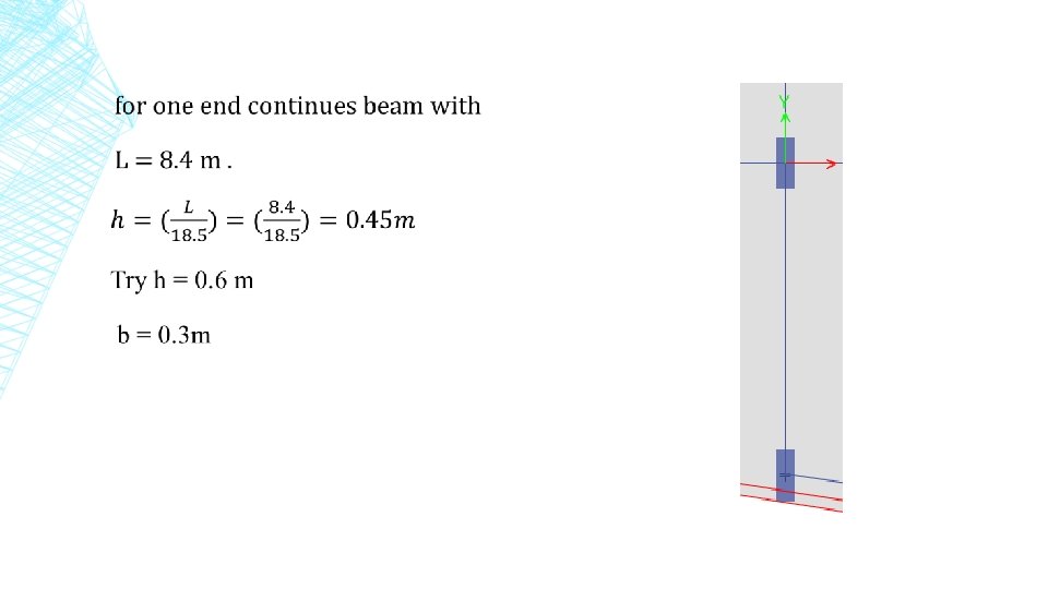
BEAMS DIMENSIONS ▪

COLUMN DIMENSIONS column dimensions found by tributary area method The dimension of column is (1400 × 500)

MODELING & CHECKES ETABs 2016, will be used. ▪ Process of modeling ▪ checks of modeling
 Define of material - Concrete concrete was used with")
Process of modeling ▪ 1) Define of material - Concrete concrete was used with ɣ=25 KN/m 3 and F'c =28 MPa So Ec = 4700×√(f'c) = 4700× √ 28= 24870 MPA
 ▪ ɣ=78. 5 KN/m 3 ▪ Fy=420 Mpa ▪ Es= 200")
- Steel (rebar) ▪ ɣ=78. 5 KN/m 3 ▪ Fy=420 Mpa ▪ Es= 200 000 MPa
 Define of sections ▪ Columns & Beams sections ▪ Shear & Retaining walls")
2) Define of sections ▪ Columns & Beams sections ▪ Shear & Retaining walls sections ▪ Slabs sections

Columns & Beams sections

Beams sections ▪ Main beam ▪ Secondary beams

Beams modifiers

Columns modofires

Shear & Retaining walls sections

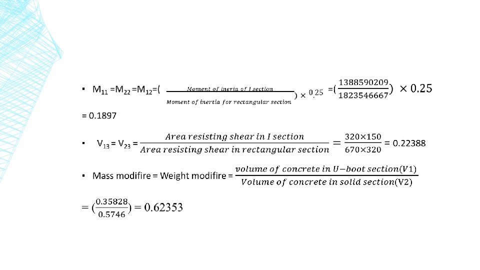
Slabs sections ▪ U- boot section ▪ solid slab

▪ U-boot slab

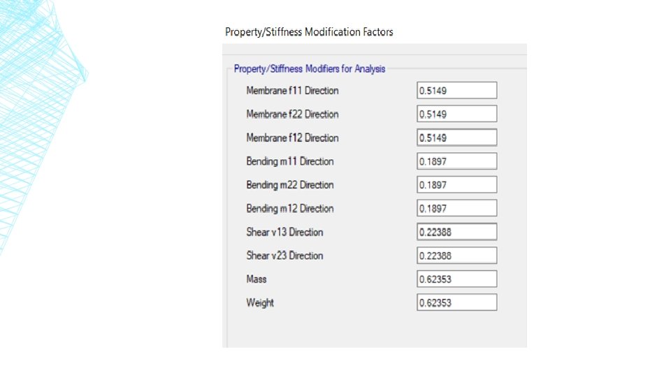
Modifiers for U-boot slab:

Solid slab ▪ Solid slab section & modifiers
Define of load and load combinations")
4)Define of load and load combinations
Define function with type of response spectrum with value")
STEPS TO DEFINE LATERAL LOAD 1)Define function with type of response spectrum with value of SDS 0. 60 And SD 1 =0. 3875
 Define load cases in two directions with type")
STEPS TO DEFINE LATERAL LOAD 2) Define load cases in two directions with type of response spectrum using the function that defined in step 1 The scale factor = ( g ×I)/R= (9810 × 1)/5=1962
 Define equivalent lateral static force in X and")
STEPS TO DEFINE LATERAL LOAD 3) Define equivalent lateral static force in X and Y directions.
 Define mass source for blocks which will be")
STEPS TO DEFINE LATERAL LOAD 4) Define mass source for blocks which will be used to find seismic weight of structure. 5) Define diaphragms for each story and it will be semi rigid diaphragm.

CHECKS OF MODEL - Compatibility check. Equilibrium check. Stress strain check. Deflection check. Modal mass participate ratio check(MPMR) Base shear check Drift check P-delta check

Compatibility check to confirm that the structural elements connect together.

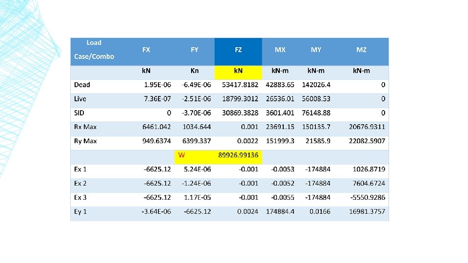
Equilibrium check ▪ This check is to confirm that weight of structure from ETABS are approximately equal to weight of structure by hand calculations. ▪ Max. allowable error in this chick 5% ▪ ETABs result:
")
Calculations - Live load Equilibrium check for total live load Story Live load (KN/m^2) Area (m^2) Total live load (KN)/story B 2 3 608. 82 1826. 46 B 1 5 608. 82 3044. 1 G 5 564. 46 2822. 3 Attic 5 337. 39 1686. 95 1 5 426. 3 2131. 5 2 3 426. 3 1278. 9 3 3 426. 3 1278. 9 4 3 426. 3 1278. 9 5 3 426. 3 1278. 9 6 3 426. 3 1278. 9 roof 3 426. 3 1278. 9 Stair slab 2 75. 46 150. 92 Sum. 19335. 63 ETABs Result 19091. 74 Error 1. 26135016 max. allowable error 5% OK
 Area")
- SID load Equilibrium check for total SID load Story SID load (KN/m^2) Area (m^2) Exterior walls on beams Total SID/story B 2 4 608. 82 0 2435. 28 B 1 4. 3 608. 82 0 2617. 926 G 4. 3 564. 46 630 3057. 178 Attic 4. 3 337. 39 1265 2715. 777 1 4. 3 426. 3 1220 3053. 09 2 4. 3 426. 3 1220 3053. 09 3 426. 3 1220 3053. 09 4 4. 3 426. 3 1220 3053. 09 5 4. 3 426. 3 1220 3053. 09 6 4. 3 426. 3 1220 3053. 09 roof 4. 3 426. 3 1220 3053. 09 Stair slab 3 75. 46 0 226. 38 total SID 32424. 171 ETABs Result 32180. 2 Error 0. 752435583 Error < 5% … OK

Dead load ▪

Dead load from slabs Equilibrium check for Dead load SLABs Dead load Story Slab weight (KN/m^2) Area (m^2) Total Slabs load/story B 2 5. 5 608. 82 3348. 51 B 1 4. 989 608. 82 3037. 40298 G 4. 989 564. 46 2816. 09094 Attic 4. 989 337. 39 1683. 23871 1 4. 989 426. 3 2126. 8107 2 4. 989 426. 3 2126. 8107 3 4. 989 426. 3 2126. 8107 4 4. 989 426. 3 2126. 8107 5 4. 989 426. 3 2126. 8107 6 4. 989 426. 3 2126. 8107 roof 4. 989 426. 3 2126. 8107 Stair slab 5. 5 75. 46 415. 03 Sum = 26187. 94753
 avg. length (m) # of beams")
Dead load from beams Beams Section area (m^2) avg. length (m) # of beams weight (KN) B 1 (70 X 40) 0. 28 7. 1 210 10437 B 2 50 X 40 0. 2 2. 1 30 315 B 3 22 X 40 0. 088 1. 9 4 16. 72 B 4 22 X 60 0. 132 3. 2 10 105. 6 B 5 32 X 40 0. 128 4. 8 102 1566. 72 B 6 32 X 60 0. 192 4. 4 35 739. 2 B 7 (70 X 30) 0. 21 6. 8 38 1356. 6 Sum = 14536. 84

Dead load from columns Columns Dead Load Story Section area Length No. in each story Weight B 2 0. 35 2. 5 11 240. 625 B 1 0. 35 2. 5 11 240. 625 G 0. 35 3 11 288. 75 Attic 0. 35 3. 27 11 314. 7375 1 0. 35 3. 06 11 294. 525 2 0. 35 3. 25 11 312. 8125 3 0. 35 3. 25 11 312. 8125 4 0. 35 3. 06 11 294. 525 5 0. 35 3. 06 11 294. 525 6 0. 35 3. 06 11 294. 525 roof 0. 35 3. 06 11 294. 525 Stair slab 0. 35 3. 32 4 116. 2 Sum= 3299. 188

Retaining Walls 5163. 6 Shear Walls 1640 Total Dead Load 50827. 57503 50005 ETABs Reading Error 1. 618363712 1. 62% < 5% …. . >>> OK

Stress strain check ▪ Check moment in frame ▪ Check moment in beam ▪ Check axial on column ▪ Check shear in slab

moment in frame ▪

moment in frame ▪ Section cut at start of frame ▪ M at start of frame = 34. 6 KN. m

moment in frame ▪ Section cut at mid of frame ▪ M at mid of frame = 81. 4 KN. m

moment in frame ▪ Section cut at end of frame ▪ M at end of frame = 69. 3 KN. m

moment in frame ▪
")
Moment in beam ▪ This check will be done for B 1 (70× 40) and will be calculated from live load (3 KN/m 2), as shown in the figure: ▪ Tributary area for B 1

Moment in beam ▪

Moment in beam M at second edge = 52. 7 KN M at first edge = 25. 38 KN. m

Moment in beam M at mid of beam = 51. 7 KN. m

Moment in beam ▪
 in 6 th floor ▪")
check axial on column ▪ For column (C 8) in 6 th floor ▪ Tributary area = 6. 9× 4. 1 = 28. 2 m 2. P (live) = live load × Area P = 3 KN/ m 2 × 28. 2 m 2 = 84. 6 KN
 = 80. 3 KN. ▪ Difference percentage")
check axial on column ▪ From ETABS(P) = 80. 3 KN. ▪ Difference percentage = (84. 6 – 80. 2655)/ 84. 6 × 100% = 5. 12 %, OK

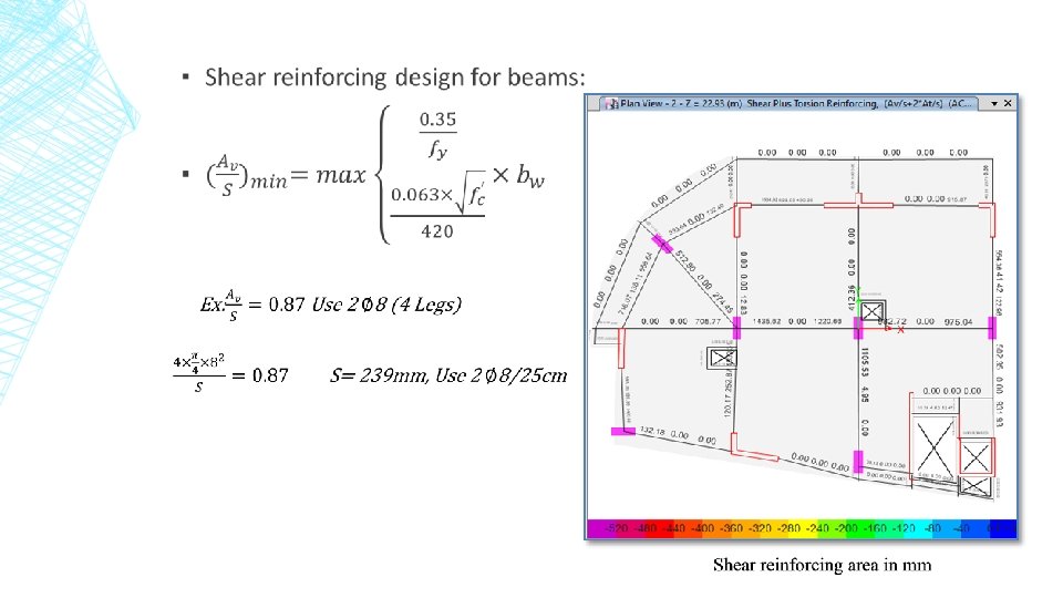
check shear for slab ▪ Shear Capacity of slab = ФVc ▪ ▪ ФVc = Ø × (1/6 ) × √(f'c) ×bw × d = 0. 75 × 1/(6 ) × √(28 ) × 150 × 280 × 1. 1 = 30. 558 KN/rib ▪ ФVc = 30. 558/0. 67 = 45. 61 KN/ m
:")
check shear for slab ▪ Check of the shear force in x-direction (V 13):
:")
check shear for slab ▪ Check of the shear force in y-direction (V 23):

Deflection check ▪ Deflection at first panel: First panel will be checked in first floor ▪ Immediate deflection = deflection in the middle of the panel – average deflection of the four beams

Deflection check ▪

Deflection check ▪

Deflection check ▪

Deflection check ▪

MPMR CHECK ▪ to find if response spectrum analysis can be made for seismic design. So The MPMR must be greater than 90% to use response spectrum analysis.

Case Mode Period UX UY UZ Sum UX Sum UY sec Modal 1 1. 500 0. 4507 0. 0322 Modal 2 1. 420 0. 0309 0. 4896 0 0. 4816 0. 5217 Modal 3 1. 003 0. 0384 1. 236 E-05 0 0. 5217 Modal 4 0. 383 0. 1078 0. 002 0 0. 6278 0. 5237 Modal 5 0. 364 0. 0023 0. 1151 0 0. 6301 0. 6389 Modal 6 0. 281 0. 0019 0. 0154 0 0. 6321 0. 6543 Modal 7 0. 185 0. 0461 0. 0012 0 0. 6781 0. 6555 Modal 8 0. 167 0. 0025 0. 0577 0 0. 6807 0. 7132 Modal 9 0. 162 0. 0001 0. 0016 0 0. 6807 0. 7147 Modal 10 0. 139 0. 019 0 0 0. 6998 0. 7147 Modal 11 0. 135 0. 0001 0. 0025 0 0. 6998 0. 7173 Modal 12 0. 124 0. 0016 0. 0131 0 0. 7014 0. 7304 Modal 13 0. 116 1. 91 E-05 1. 281 E-05 0 0. 7014 0. 7304 Modal 14 0. 111 0. 0005 0. 0434 0 0. 702 0. 7738 Modal 15 0. 105 0. 0486 0. 0001 0 0. 7505 0. 774 Modal 16 0. 099 0. 0022 0. 0001 0 0. 7528 0. 774 Modal 17 0. 088 0. 0007 0. 051 0 0. 7535 0. 8251 Modal 18 0. 082 0. 0734 0. 0014 0 0. 8269 0. 8265 Modal 19 0. 076 0. 0085 0. 0409 0 0. 8355 0. 8674 Modal 20 0. 069 0. 0429 0. 0002 0 0. 8783 0. 8676 Modal 21 0. 066 0. 0074 0. 0329 0 0. 8858 0. 9005 Modal 22 0. 061 0. 0014 0 0 0. 8871 0. 9005 Modal 23 0. 059 0. 0067 0. 0018 0 0. 8939 0. 9023 Modal 24 0. 059 0. 0005 0. 0122 0 0. 8944 0. 9145 Modal 25 0. 058 0. 0066 0. 0015 0 0. 901 0. 9161

BASE SHEAR CHECK ▪

BASE SHERA CHECK ▪

BASE SHEAR CHECK ▪

DRIFT CHECK ▪

IN X - DIRECTION

IN Y -DIRECTION

P-DELTA CHECK ▪

THETA IN X –DIRECTION

THETA IN Y -DIRECTION

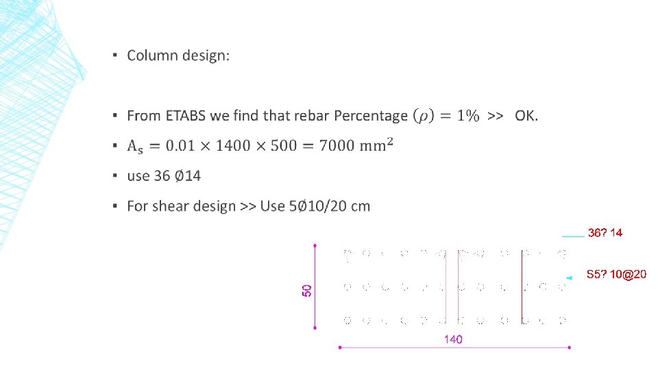
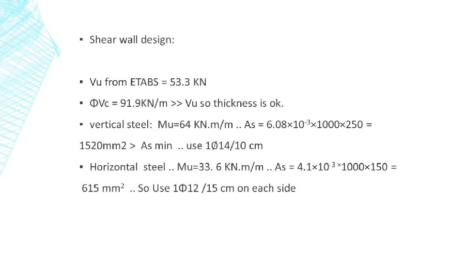
DESIGN AND DETAILING ▪

▪ Beams Design:

▪ Example of beams design:

▪ Footing design ▪ Using safe program ▪ K= factor × qall ▪ K=120× 300 = 36000 ▪ Check for punching shear : ▪ There is no punch on the footing as we see on picture.

▪ Check bearing capacity: ▪ As we see on the picture there is no regions on footing that above bearing capacity

▪ For footing we use: ▪ Q = 300 KN/m^2. . H = 600 mm. . D = 520 mm. . ▪ Ex : ▪ More and more detailing in Auto. CAD drawing and word report

- Slides: 105