Stress State Simulation for Reactor and Steam Generator


 -")


 Intermediate Primary Leak")


- Slides: 25
Stress State Simulation for Reactor and Steam Generator Pressure Vessels Kharchenko V. G. S. Pisarenko Institute for Problems of Strength 2 nd Hungarian-Ukrainian Joint Conference on «Safety-Reliability and Risk of Engineering Plants and Components » Kiev, Ukraine 19 -21 September 2007
INTEGRITY AND LIFETIME ASSESSMENT OF NPP COMPONENTS - Reactor pressure vessel; - Steam generators; - Pipelines Primary Circuit of WWER NPP
When assessing the RPV or SG structural integrity, the accuracy of determination of changes in the stress state and stress intensity factor (SIF) values under thermomechanical loading also plays an important part. The stress and SIF values and peculiarities of its variation in space and time are affected by a large number of factors: loading conditions; sizes and locations of cracks; Stress intensity factor versus crack-tip temperature (plastic calculation) for RPV under PTS, from NUREG/CR-6651, Task metal characteristics; T 1 C 2 accuracy methods and schemes Not only materials characteristics are big scatter, stress for calculations; state and FM parameters often have big differences too and so on.
Development of the methods and software for the stress-strain state calculations for complex three-dimensional structures Mixed schemes of the finite-element method (MFEM) for thermoelasticity and thermoplasticity Original 2 D and 3 D Software RELAX, SPACE, PIPE, and other packages Various Tests: • Pure bending of the beam • Three-point bending of the beam with the edge crack, etc Comparisons with commercial software (ANSYS and so on), analytical and exp. results
Examples of the Test Tasks Solution Accuracy Evaluation of the Software Pure bending of the beam n Error in the stress determination Three-point bending of the beam with the edge crack Error in the SIF determination Our MFEM
Structural Integrity and Lifetime of Steam Generator Elements with damage: -Heat-change tubes - Collectors -узел соединения “горячего” коллектора и патрубка ПГ Crack place Experimental Data on-line 3 D Stress Calculation Key problems analysis experimental data stress calculation Integrity and Lifetime Assessment
3 -D calculation models
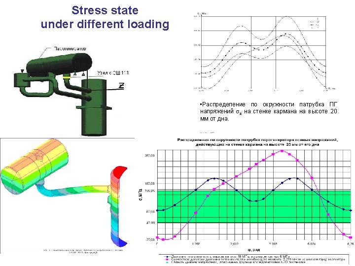
Evaluation of the Validity and Accuracy of the Schemes for Modeling Accuracy of Different Software and Meshes Different FE Meshes Comparison of Calculation and Measurements • Stresses σZ on the outer surface of the welded joint in the region of strain gage mounting: • 1 – numerical calculation (P 1/P 2 = 16/6 MPa, M = 2. 279 MH m); • 2 – data of full-scale strain measurements
Comparison of calculations results Distribution of the stresses acting on the “pocket” surface on the side of the nozzle 20 mm away from its bottom under hydrotest • - EDO Gidropress, software ANSYS - our results, software SPACE
Modelling of stress-strain state of a Welded Joint of Hot Collector to Nozzle of SG PGV-1000 during Local Heat Treatment after Repair Schematic of the SG Element and mounting of heating elements: 1 - steam generator shell with heat insulation; 2 – nozzle; 3 – “pocket”; 4 – heat insulation; 5 - welded joint; 6 – heating elements; 7 –collector; 8 – heat insulation plugs Residual stresses (φ = π) Temperature distribution
Residual Stresses of the SG Element after Local Thermal Treatment Equivalent Stresses а) - φ = π; b) - φ = 0 Resume: Local Stresses are High Level in SG Element after Local Thermal Treatment and under Service Loads Distribution of the residual stresses acting on the “pocket” surface on the side of the nozzle 20 mm away from its bottom
STRENGTH AND LIFE CALCULATION of reactor pressure vessels of NPPs Neutron fluence in pressure vessel wall Ф(x, y, z) Residual stresses Key issues Conditions of inservice thermomechanical loading, specifically in emergency events – thermal shock Mechanical properties of base metal, welds, cladding and their in-service degradation Stress state, temperature fields, thermal hydraulics, Defects (actual and hypothetical) Strength of RPVs with cracks - limit state criteria; - postulation of cracks - calculation of SIF KJ - fracture toughness KJС
Stress State in RPV under PTS We use original 2 D and 3 D Software RELAX, SPACE and schemes with and without built-in cracks We analysed accuracy of stress and FM parameters ( SIF, COD) determination for linear and non-linear cases 3 D FE Model Input data for 3 D accidents cases as function of time and space: - coolant temperature in the downcomer - heat transfer coefficient - primary circuit pressure
SIF Calculations To calculate the SIF, we considered two basic options : – engineering methods, whereby use is made of analytic formulae or tabulated collections of stress intensity values for given defect and vessel geometries; – cracked body finite element analyses, in which the crack is directly modelled in the mesh and subjected to the appropriate loadings
RPV with a built-in crack Crack location area WWER 1000 RPV FEM model with surface or sub cladding crack (a=11 or 19 mm, a/c=1/3 or 2/3) in weld 4
Temperature and Stress State Comparison of Temperature in RPV wall (EDO Gidropress, Marc and IPS, SPACE) 3 D Distribution of Temperature at t=500 s Comparison of Stresses in RPV wall for Different FE Meshes
Stress Distributions with and wthout residual stress
SIF Distribution along Crack Variation in the stress intensity factor KI along the longitudinal half-elliptical crack front under PTS a/c = 2/3, a/t = 1/10 SIF comparisons by different procedures (WPF and EVI)
Comparison of SIF calculations ( EDO Gidropress, Marc and IPS, SPACE) Intermediate Primary Leak (Break of SG Collector Head). Weld 4. Circumferential cracks, a=11 and 19 mm, а/с=2/3. Small Primary Leak (D 36 mm). Weld 4. Circumferential cracks, a=11 and 19 mm, а/с=2/3.
Crack Open Displacement Elastic case Elasto-plastic case with residual stresses
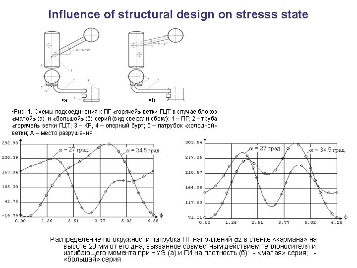
Conclusions • Methods and software have been improved for the calculation of the stress state of complex spatial structures with cracks, which is based on the mixed schemes of the finite element method; • Various numerical and engineering procedures for determining the stress intensity factors for a reactor pressure vessel have been compared • Comparison of the results of the stress state calculation for RPV and SG elements obtained by the authors and at the Design Bureau “GIDROPRESS” revealed a good correspondence and confirmed the applicability of the developed computational schemes, calculation procedures, and software; • The development of 3 D models for the SG welded joint and their application for calculations made it possible to establish a nonmonotonic stress distribution along the circumference of the welded joint with two maxima. The maximum (comparable to the yield stress) levels of tensile stresses are reached in the local region at the fillet for various regimes of post-repair heat treatment and operation conditions. The level of the maximum stress is influenced appreciably by the bending moment induced by thermal expansion of the Main Circulation Pipeline
Thank You For Attention !