Strengthening of damaged PSC bridge girders with Carbon

Strengthening of damaged PSC bridge girders with Carbon Fibre Reinforced Polymer “CFRP” System S. N Agarwal, GM/SER K. C Swami, CBE/WR Avinash Kumar, Dy. CE/D/WR
 on Khan River")
BRIDGE No. 114 (4 X 18. 3 m) on Khan River

Salient Features of Bridge No. 114 ü Span Configuration: - 4 X 18. 3 m ü Superstructure: -Twin PSC girders with RCC deck Slab ü Section –Godhra-Ratlam (Ratlam Division of WR) ü Year of Construction -1958 -60 ü Wt of one Span – 145 MT ü Depth of Girder – 2130 mm ü Loading Standard – BGML ü Height of bridge (bottom of girder – Bed Level) -14. 0 m

Defects identified and Action Taken ü Multiple vertical structural cracks found in girders (mainly originating from bottom) ü Other deteriorations in slab and girders also noticed. ü Cracks were active (opening & closing)under traffic ü Speed reduced to 20 kmph in March-2014 ü Tell tales were provided

Defect: - Vertical Flexural Cracks 5

Visible Cracks in Web of PSC girder
 Rebound hammer test – Compressive strength of concrete")
Tests carried out before strengthening (i) Rebound hammer test – Compressive strength of concrete Ultrasonic pulse velocity test – homogeneity and quality of concrete, presence of voids, cracks etc. (ii) Core test – Comp strength of concrete (iii) Tension test – Tensile Strength of Prestressing wire (iv) Concrete Scanning System – used for locating prestressing cables and finding their size. (v) Load tests for measurement of deflection using LVDT– to compare pre and post strengthening results(vi) Test for measurement of natural frequency using accelerometer– to compare pre and post strengthening results 7

Results of NDT tests Span No. Span -2 Span-4 Average of UPV Average comp readings (km/sec) strength Rebound Hammer test (Mpa) 3. 42 54. 3 3. 40 51. 6 Pulse Velocity Value (Km/sec) Concrete Quality Above 4. 5 Excellent 3. 5 -4. 5 Good 3. 0 -3. 5 Medium Below 3. 0 Doubtful

Deflection Test For Natural Frequency � WAG 7 locomotive was used for load testing
 Repair of corrosion related deterioration (ii) Patch Repair")
Method of Strengthening Preparatory Work (i) Repair of corrosion related deterioration (ii) Patch Repair using Polymer Modified Mortar (iii) Epoxy Grouting – Pressure injection of cracks Installation of CFRP System (i) Prestressed CFRP laminate - For enhancing Flexural stiffness - 5 nos of 100 mm width and 2. 4 mm thick in each girder (ii) CFRP sheet Wrapping - For enhancing Shear Strength - Provide additional bond strength to laminates - 1 and 2 layers of 500 mm width 430 GSM carbon fiber sheet 800 mm c/c Application of Protective Coating - to protect bonded CFRP from environmental effects 10

Repair of Corrosion related deterioration -Application of anticorrosive paint

Application of Polymer modified mortar
")
Injection in Cracks (Epoxy grouting)

Surface Preparation
")
Application of Putty ( Removing surface undulation)
")
Application of Primer (Bonding Coat)

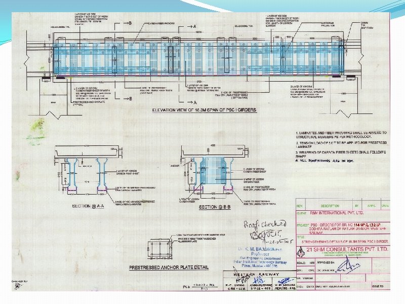
Installation of CFRP System Application of CFRP laminates Clamping Device Anchor Plate CFRP Laminate 100 x 2. 4 mm Hydraulic Jack Cylinder Body 80 KN Bottom Face of PSC Girder

RCC SLAB PSC GIRDER CFRP Laminate CFRP Sheet 500 mm wide Cross Section CFRP Laminate 100 x 2. 4 mm 800 mm c/c Elevation of PSC girder RCC SLAB PSC GIRDER

Fixing of Hydraulic Jack and application of prestressing force

Pre stressing of laminate

Pre stressed carbon laminates in bottom of girder

Carbon Fiber Wrapping
")
Carbon Fiber Wrapping (duly saturated with saturating resin)

Strengthened PSC Girder 25

Acceptance criteria �Cracks: - No further progression of cracks after rehabilitation. �Deflection: - Fifty to seventy percent of the excess deflection as compared to uncracked girder will be reduced �Natural frequency: - the excessive natural frequency will come within 25% of the value of uncracked girder. Note: - In case natural frequency is already near to or within 25% of the natural frequency of uncracked girder, the respective above criteria cannot be applicable.

Effectiveness of Strengthened deck Deflection of girders at mid point for WAG-7 Loco Span No. Deflection in mm Before After Strengthening g % reduction % recovery of excessive deflection 1 st, Uncracked Girder 2. 79 2 nd, Cracked Girder 3. 84 3. 07 20. 05 73. 33 4 th, Cracked Girder 4. 06 3. 16 22. 16 70. 86 Remark -Excess deflection reduced more than 50%
 Frequency in Hz Span")
Effectiveness of Strengthened deck Natural frequency of Girders (in Hertz) Frequency in Hz Span No. % Increase Before Strengthening After Strengthening 1 st, Uncracked Girder 9. 58 -- 2 nd, Cracked Girder 8. 64 9. 29 7. 52 4 th, Cracked Girder 8. 44 8. 70 3. 08 (i) Natural frequency of Cracked girders are already within 25% of the natural frequency of uncrackd girder. (ii) However natural frequencies of repaired girders are more, which indicate that flexural stiffness has increased after repair.

Health Monitoring of Repaired Girders Deflection of repaired girders in mm with time Date of recordings Span 07. 15 10. 08. 15 26. 10. 15 29. 01. 16 23. 08. 16 22. 10. 16 2 nd -- 3. 07* 3. 13 3. 11 3. 10 3. 07 4 th 3. 16* 3. 11 3. 17 3. 12 3. 14 3. 12 *-values just after repair

Effectiveness of Strengthened deck Deflection of girder at mid point ( For WAG 7 Load) in mm Span No. Before Strengthening After Strengthening Load Test FE Analysis 2 nd (distressed girder) 3. 84 3. 07 3. 10 4 th (distressed girder) 4. 06 3. 16 3. 21

Effectiveness of Strengthened deck Deflection of girder at mid point ( For WAG 7 Load) in mm Span No. Before Strengthening After Strengthening Load Test FE Analysis 2 nd (distressed girder) 3. 84 3. 07 3. 10 4 th (distressed girder) 4. 06 3. 16 3. 21
 Items Details Grade of concrete, girder M 35 (verified from")
Design Details (material properties) Items Details Grade of concrete, girder M 35 (verified from NDT tests and core sample) Grade of concrete, deck slab M 20 (verified by NDT tests) No of cables in each girder 6 No of strands in a cable 12 Diameter of one strand 8 mm Ultimate strength of cable 1600 N/mm² (from testing)

Material properties of CFRP system CFRP Laminate CFRP Dry sheet Width 100 mm Width 500 mm Thickness 2. 4 mm Thickness 0. 25 mm Modulus of Elasticity 150 GPa Modulus of Elasticity 230 Gpa Limiting Strain 0. 012 Limiting Strain 0. 014 Limiting Stress 1800 N/mm² Limiting Stress 3220 N/mm²
 Design philosophy -ACI 440. 2 R-08 has been followed - Published")
Design Consideration (i) Design philosophy -ACI 440. 2 R-08 has been followed - Published by American Concrete Institute Design was Proof checked by Prof K. M Bajoria of IIT/Mumbai (ii) Design Flexural strength determined based on Strain compatibility, Internal force equilibrium and Controlling mode of failure. (iii) The Strengthened Girders have been designed to satisfy Ultimate limit state as well as serviceability limit state. 34

Probable Failure mode ü Crushing of concrete in compression before yielding of prestressing steel and rupture of laminates ü Yielding of prestressing steel in tension followed by rupture of laminates ü Yielding of steel followed by concrete crushing ü Debonding of CFRP laminates from concrete substrate

Flexural strength – Ultimate limit state üLoading standard considered 25 t-2008 üDesign Flexural strength = 18241 KN-m üApplied factored Moment = 17587 KN-m < 18241 KN-m ( Less than Design Flexural moment, hence OK)

Stresses in Service condition ü Compressive stress in concrete should be less than 0. 45 fc Comp stress = 6. 4 Mpa < 7. 2 Mpa ü Stress in prestressing wire should be less than 0. 72 fpu to avoid yielding of steel in service Stress in steel = 705 Mpa < 1140 Mpa ü Stress in CFRP laminates should be less than 0. 55 ffu to avoid creep rupture under sustained load and fatigue due to cyclic stress Stress in laminate = 410 Mpa < 990 Mpa

Advantages of prestressing laminates �Induce comp stresses in bottom of girder �May close pre existing cracks and increase stiffness �Laminate made active to participate to carry load due to DL+SIDL – 0. 22 % strain (more utilization) �Improve serviceability and durability of girders �Increase the ultimate moment of resistance by delaying failure mode associated with delamination as the ends are anchored.

Conclusions � The use of CFRP laminates increases the flexural stiffness and natural frequency of the cracked prestressed girders. � Proper CFRP repair scheme can be designed by following provisions of ACI -440 -2 R for capacity enhancement and desired mode of failure of repaired PSC girders. � Results of load tests after strengthening are in good agreement with the results obtained from FE analysis. � The deflection of repaired girders are almost constant after passing more than one year – thus proved an effective method of strengthening of cracked PSC girders � First time implemented in Indian Railway and proved very promising, effective and economical for organization like Railway where work has to be done under traffic or a traffic block of 2 -3 hours –traffic can’t be stopped or diverted

THANK YOU
- Slides: 40