STREAM GAUGING LECTURE 8 STREAM GAUGING Stream flow


- Slides: 36
STREAM GAUGING LECTURE 8
STREAM GAUGING Stream flow data is primarily gathered by hydrologists for hydrologic studies To an engineering hydrologist stream flow data is dependent variable in most studies Generally it is difficult to make direct and continuous measurement of discharge but relatively simple to obtain a continuous record of stage Adequate co-relation is developed in this regard at a certain stream section
IMPORTANCE OF STREAM GAUGING Streams provide water supply for human settlements and animals Irrigation water for plants Energy for power production Floods cause extensive hardship and damage For design of bridges, culverts, spillways, reservoirs, food plain delineation and flood warning systems
SELECTION OF STATION SITE The control is a section or a reach of a stream which controls the relationship between the stage and discharge The stage gauge is therefore installed within the area of influence of control Control should be permanent Artificial controls are built in a stream channel to stabilize relation between stage and discharge, they may be low dams, broad crested weirs or partial flumes
SELECTION OF STATION SITE The stream course is straight for about 300 feet upstream and downstream of the gage site. The streambed in the vicinity of the site is not subject to scour and fill. It is also free of aquatic plants. The banks of the stream channel are permanent. They are free of brush and high enough to contain floods. Opportunity to install an artificial control Possibility of no backwater effect from d/s tributaries Good metering section Minimum debris and floating matter The site is accessible for installation and operation and maintenance of the gaging site. The selection of a gaging site is again a compromise between these criteria. Power and telephone line facility
STREAM GAUGING Data gathered at a stream gauging station comprises of Stage Discharge Sediment (to develop sedigarphs) Uses of this data are Use and control of water in a stream (drinking, municipal purposes, irrigation, industries, power generation) Control over hazardous situations e. g. , Floods
STAGE Elevation of surface of water above an arbitrary datum River stage is an important concept when analyzing how much water is moving in a stream at any given moment A record of stream stage is useful in itself for designing bridges, embankments, levees, and other structures affected by stream elevations, or in planning for the use of flood plains
STAGE Datum of the gauge might be a recognized datum such as North American Vertical Datum of 1988 (NAVD 88) or an arbitrary datum. Sometimes datum is taken as Mean Sea Level (MSL) Select the arbitrary datum plane for a stream gauging site to avoid negative values of gage height. This requires the arbitrary datum plane to be below the lowest expected gage height, which will be at, or below, the elevation of zero flow on the control for all conditions. For each gauging station, maintain a permanent datum that has at least three permanent reference marks that are independent of the gage structure The gauge datum may need to be changed if there is excessive channel scour or a manmade channel change
STAGE MEASUREMENTS
NON-RECORDING/MANUAL GAUGES A few non-recording gauges are as follows: Staff Gauge Wire-weight Gauge Float type gauge Electronic Tape Gauge
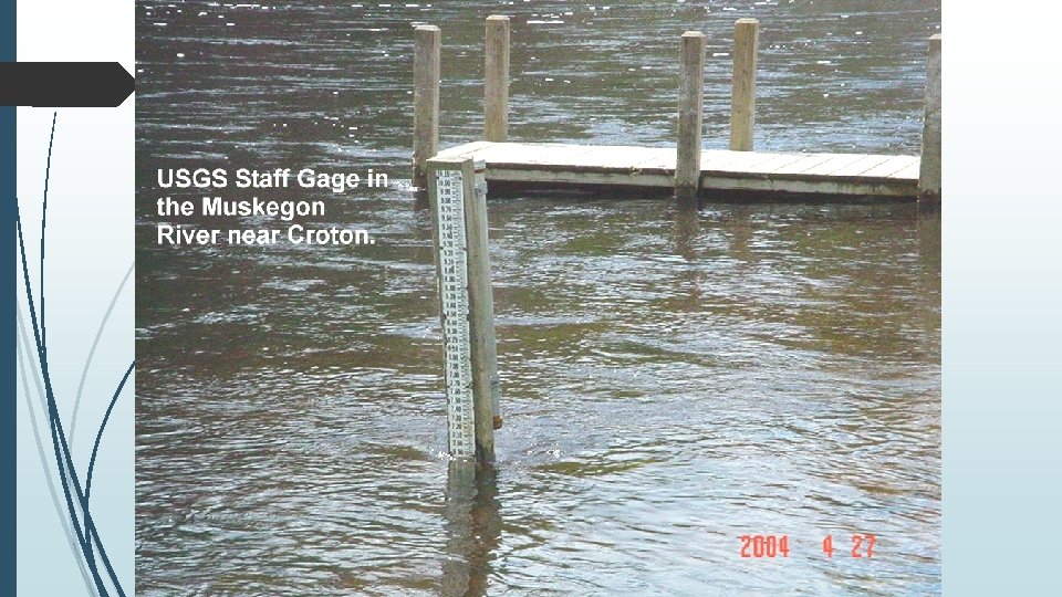
MANUAL/NON-RECORDING STAGE GAUGES Staff Gauge: Simplest method to measure stage This is a scale set so as a portion of it is always immersed in the water The staff gage is either vertical or inclined. The standard USGS vertical-staff gage consists of porcelain-enameled iron sections 4 in. wide and 3. 4 ft long and graduated every 0. 02 ft Gauge may consist of a vertical scale attached to a bridge pier or piling
MANUAL/NON-RECORDING STAGE GAUGES Gauge scale may be printed on the existing structure or on special gauge boards
MANUAL/NON-RECORDING STAGE GAUGES Gauge scale may be printed on the existing structure or on special gauge boards
MANUAL/NON-RECORDING STAGE GAUGES An inclined staff gage is used for an outside gage and usually consists of a graduated heavy timber securely attached to a permanent foundation
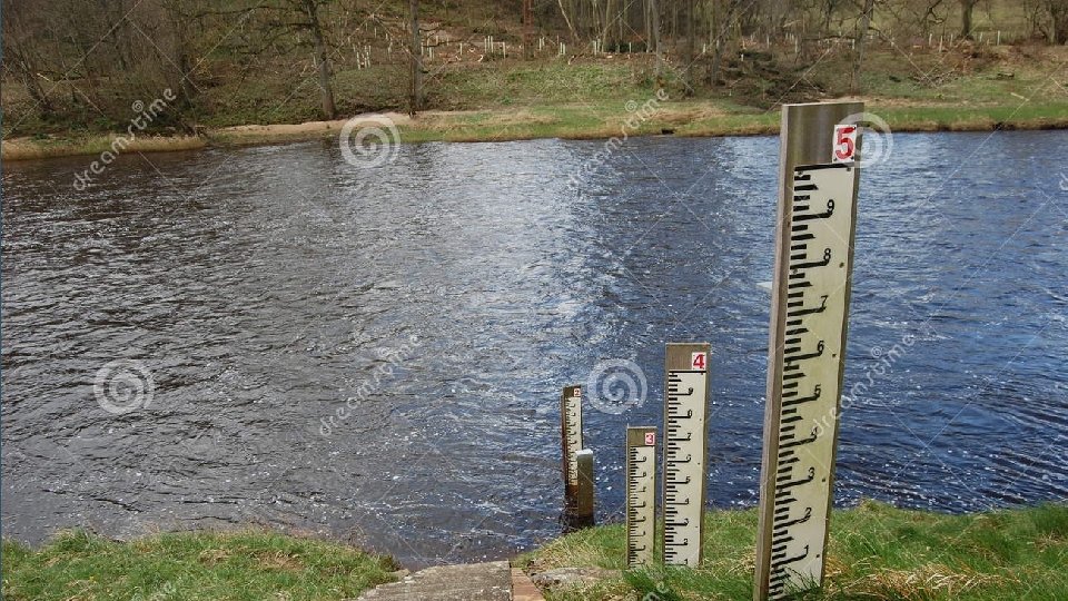
MANUAL/NON-RECORDING STAGE GAUGES If no suitable Structure is present on site then sectional gauging may be used
MANUAL/NON-RECORDING STAGE GAUGES When there is possibility of silt or mud, staff with raised graduations is preferred During normal flow season, the gauge is read from 06: 00 to 16: 00 daily In flood continuous record is obtained
MANUAL/NON-RECORDING STAGE GAUGES Wire Weight Gauge: Canfield wire weight gauge Type- A wire weight Gauge The type A wire-weight gage is usually attached to a bridge handrail and is generally used as an outside auxiliary gage. At some sites it is used as a reference gage.
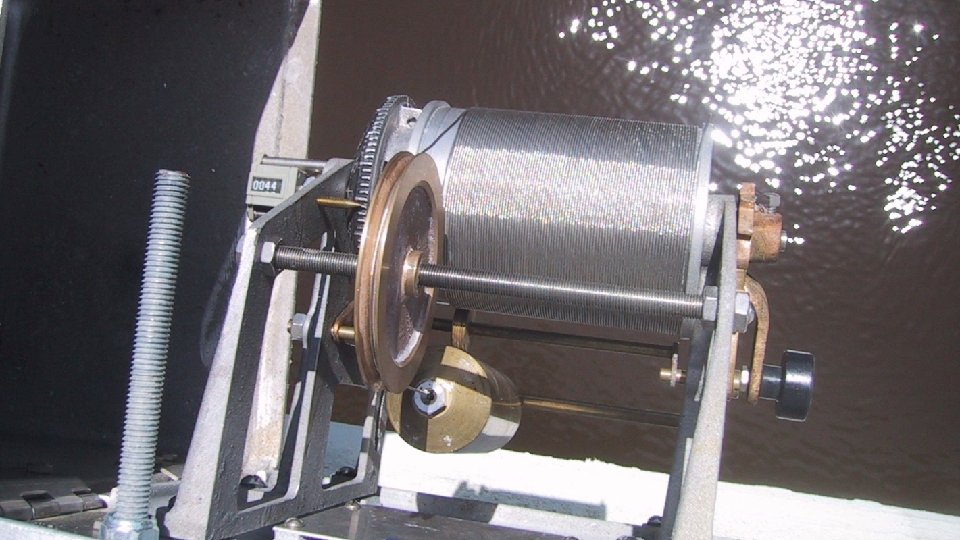
MANUAL/NON-RECORDING STAGE GAUGES Wire Weight Gauge: A type A wire-weight gage consists of a drum wound with a single layer of stainless steel 0. 045 inch cable, a bronze weight attached to the end of the cable, a graduated disc, and a counter, all within a cast-aluminum box Disc is graduated in tenths & hundreds of a foot Circumference of the reel is adjusted so that one revolution covers 1 ft of wire length No. of revolutions are counted using the counter
MANUAL/NON-RECORDING STAGE GAUGES Wire Weight Gauge: Disk is permanently connected to the counter Weight is lowered from a bridge or other overhead structure until it reaches water surface Reading is taken when the bronze weight touches the surface of water Gauge is usually fixed on some girder or bridge By subtracting the length of the line paid out from the elevation of a fixed reference point on the structure water surface elevation can be determined H = g-h
MANUAL/NON-RECORDING STAGE GAUGES Wire Weight Gauge: A cantilevered wire-weight gage is sometimes used where outside staff gages are hard to maintain and where a bridge, dock, or other structure over the water is not available for the location of a wire-weight gage.
MANUAL/NON-RECORDING STAGE GAUGES Float Type Gauge: Dial Installed in stilling well to avoid waves effects The gauge consists of a graduated steel tape, counter weight and pulley Stream/Channel Pulley Counter weight As the water level rises, float rises and needle moves on the counter Float Intake Pipe Stilling Well
MANUAL/NON-RECORDING STAGE GAUGES Float Type Gauge:
MANUAL/NON-RECORDING STAGE GAUGES VV Electronic Tape Gauge: It consists of a steel tape graduated in feet , a cylindrical weight, a reel for the tape, a battery, a voltmeter One terminal of the battery is attached to the ground connection and the other terminal to voltmeter Tape Ground Weight Circuit Diagram Other terminal of the voltmeter is connected through the frame reel to tape and weight The weight is lowered until it contacts the water surface, this contact completes the electric circuit and produces a signal on voltmeter Reel Volt Meter Tape The tape reading is then taken Weight Counterw eight Schematic Sketch
MANUAL/NON-RECORDING STAGE GAUGES Electronic Tape Gauge:
RECORDING GAUGES Float type Gauge: Manual gauges are simple and inexpensive but must be read frequently to define rating curve accurately when stage is changing This gauge produces a continuous graphic record A float generally housed in a stilling well with a shelter over it Float rises with rise of water surface in the well which is actually the stage in the stream or channel With this float is attached a pointer which moves on a barrel Barrel revolves with clock driven mechanism and has a chart pasted on it
RECORDING GAUGES
RECORDING GAUGES Stream and reservoir gages require some type of instrument shelter, and in the case of gages that use float sensors, they also require a stilling well The stilling well protects the float and dampens the fluctuations in the stream caused by wind and turbulence, Stilling wells also protect the gauges from floating debris Stilling wells are made of concrete, reinforced concrete, concrete block, concrete pipe, corrugated -galvanized-steel pipe, aluminum pipe, PVC pipe and occasionally wood
RECORDING GAUGES The stilling well should be deep enough for its bottom to be at least a foot below the minimum stage anticipated Its height should be enough to accommodate a flood of frequency 1 in 50 years The open bottom type stilling well has the advantage of being less likely to fill with sediments
RECORDING GAUGES Reinforced concrete stilling well
RECORDING GAUGES Generally two or more intake pipes are places from stilling well into the stream Intake should be 0. 5’ lower than the lowest expected stage and 5’ above the bottom of stilling well to prevent silt buildup It is customary to install gauges inside and outside the well to check the performance of recorder
CREST STAGE GAUGES Crest stage gauge is simple, economical , reliable and easily installed device for obtaining the elevation of the flood crest of streams This gage is low cost solution for supplementary record keeping or in situations where recorders are not justified economically or where manual gauges are inadequate Many different types of crest-stage gages have been tested, the most functional one is a vertical piece of 2 inches galvanized pipe containing a wood or aluminum staff held in a fixed position with relation to a datum reference.
CREST STAGE GAUGES Small amount of ground cork is placed in perforated cup As the water level rises in the pipe cork floats with the water and adheres to the staff at the highest level The staff can be removed and the crest reading is recorded Cork is then wiped off and staff is ready to be replaced in the pipe
CREST STAGE GAUGES Pipe Cap Brackets Graduated Staff that fits inside the pipe Culvert Wall Holes to admit water Pipe Cap Crest-stage Gauge Assembly