Stove Camp 2016 Green Smart 101 What is


 Ø Used to turn main burner ON/OFF Ø Switch")
 Ø Opens and closes the split flow (comfort control)")
 Ø Ø Switches between standing pilot and continuous pilot Used")
 Ø Ø Ø Used on all Green. Smart appliances")
 Valve (250‐ 01423) Ø Used on all Green. Smart appliances (GS")
 §")
 – (250‐ 01566) (250‐ 03263 used on non")
 (GS 1) (250‐ 03824) Ø Central Processor (brain) for")
 (250‐ 01577) Ø Converts 120 v line voltage to 7")
 Ø With power cord (250 -01458) § All fireplaces")
 ‐ 02302) Ø Ø Ø On/ Off/ Remote Slide Switch")
 (250‐ 03825) Ø Ø Ø Ø Central processor (brain) for")
 (GSR 2) (250‐ 03826) Ø Ø Ø Ø Central processor")
 Ø Ø On/Off/Remote switch Learn button for remote synchronization")


 Ø Sheathing the Rectification Rod")
 w/ Sheathed Shepherds Hook Rectification Rod (2014/ 2015) Ø")
 & DFC (GS 1) Module Power Increased (end of 2014) Ø")
 & DFC (GS 1) Improved FFRT Module (Fall of 2016) Ø")
 Ø Customers with the New GSR 2 Wall")
 Ø Silicone Off Gas during burning §")
 Ø All Green. Smart Components are tested in house")
 Ø Continuous Pilot Shutdown Safety Check § When Operating")


")


")


")


")


 System")
 Ø Audible Beep § One Audible Beep – Low")
 Ø Yellow Light § Must be on to sync")


- Slides: 74
Stove Camp 2016 Green. Smart 101
What is Green. Smart? Ø Gives the customer the ability to run there gas appliance in IPI or CPI pilot modes. Ø Most Green. Smart appliances come standard with the Comfort Control feature which offers a turn-down ratio up to 72%. Ø 2 Operating choices for the customer – Basic or Green. Smart Remote Control Ø Remote System offers multiple modes of operation – Manual, Programmable Thermostat, or “Smart” Thermostat Ø Green. Smart Remote Control is a full functioning remote system, not only allowing for the customer to turn on the flame, blower, accent lights, comfort control, pilot (GSR 2), and thermostat mode, but also the intensity of the flame, blower, and accent lights (GSR 2)
IPI vs. CPI Pilot Mode Ø IPI=Intermittent Pilot Mode § Pilot only runs when the main burner is turned on. § Advantages-Fuel Saving Cost § Disadvantage-Does not keep venting & firebox warm, causing draft problems in cold climate areas Ø CPI=Continuous Pilot Mode § Pilot runs even when the main burner is turned off § Advantages-Keeps the venting & firebox warm allowing for proper draft in cold climates. Better overall performance. § Disadvantage-Pilot is running when the main burner isn’t on, adding additional operating cost. Ø Green. Smart Systems can be easily switched from IPI to CPI mode with the flip of a switch or the push of a button. Travis recommends running the continuous pilot in cold operating climates.
Geography: Component Names & Functions
Main Burner Switch (250‐ 02013) Ø Used to turn main burner ON/OFF Ø Switch has 2 male spades, use one top and one bottom as illustrated Ø Used only in base systems (GS 1 & GS 2) Ø Discarded when unit is upgraded to GS Remote
Comfort Control Switch (250‐ 01569) Ø Opens and closes the split flow (comfort control) valve for rear or outside burner functions Ø Used only in base systems (GS 1 & GS 2) Ø Discarded when unit is upgraded to GS Remote
IPI/CPI Switch (250‐ 01578) Ø Ø Switches between standing pilot and continuous pilot Used in base systems (GS 1 & GS 2) Used in GS 1 Remote System Not used with GSR 2 Remote System
Gas Control Valve (250‐ 01422) Ø Ø Ø Used on all Green. Smart appliances (GS 1 & GS 2) Allows for gas to become present at pilot and burner Pilot adjustment screw Pressure taps (incoming and outgoing) Electrical spades for voltage testing (orange, green) Manual High/Low regulator for pressure adjustments § Note: GSR units come standard with NG stepper motor
Split‐Flow (Comfort Control) Valve (250‐ 01423) Ø Used on all Green. Smart appliances (GS 1 & GS 2) (Except 616 DF, 564 DF, 3615, 4415, 6015) Ø Allows on/off control of a portion of the burner Ø In a base system, batteries needed to function
Pilot Assembly Ø Ø SIT Pilot Assembly § 2 -way hood (250 -01541) § 3 -way hood (250 -02205) 33 DVI & Cypress § Spark Rod (250 -02091) ignites gas Pilot Sensor (250 -02092) confirms pilot is lit before gas is allowed to flow to the main burner Ø PSE Pilot Assembly § 2 -way hood (250 -02761) § 3 -way hood (250 -02762) DVL, 33 DVI, 864 HO, & Cypress only § 3 -way hood (250 -02793) 616 only Ø Pilot Sensor (250 -02777) Ø No replacement part for pilot hood or spark rod.
Stepper motor Ø Natural Gas (NG) – (250‐ 01566) (250‐ 03263 used on non split‐flow units) Ø Liquid Propane (LP) – (250‐ 01463) Ø Used in GS 1 and GS 2 remote upgrade kit Ø Electronically modulates burner up and down Ø Works in conjunction with remote transmitter Ø NG stepper motor standard on GSR 1 and GSR 2 units
Digital Fireplace Control Module (DFC) (GS 1) (250‐ 03824) Ø Central Processor (brain) for all Green. Smart 1 appliances Ø Provides Spark and monitoring of the pilot Ø Controls operation of the gas valve Ø Contains audible tone speaker for diagnostics
AC Adapter (GSB 1) (250‐ 01577) Ø Converts 120 v line voltage to 7 v DC power in base GS 1 systems Ø Polarity is critical to properation § If wires are reversed pilot will not light Ø Discarded when unit is upgraded to GS remote system
Fan Control Module (GSR 1) Ø With power cord (250 -01458) § All fireplaces and Stoves Ø With Molex connector (250 -01754) § DVL and DVS inserts Ø Provides adjustable power for fan Ø Switched power for accent lights Ø Controlled by remote via the receiver Ø 2 replaceable fuses inside § 5 amp fuse – lights and fan circuit § 6 amp fuse – constant 120 v Ø Used in upgraded GS 1 remote systems
Remote Receiver (GSR 1) ‐ 02302) Ø Ø Ø On/ Off/ Remote Slide Switch Learn Button for remote synchronization Holds 4 AA batteries used during a power outage Receives signal from transmitter Built-In blower timer: 5 min. on, 12 min. off (250
Integrated Fireplace Control Base(IFC) (250‐ 03825) Ø Ø Ø Ø Central processor (brain) for all Green. Smart 2 base appliances Provides the spark and monitoring of the pilot Controls operation of the gas valve A/C connects to IFC (eliminates A/C Adaptor) Fuse Protected (3. 15 A) 24 Hour CPI Shut Down/ Relight safety check Discarded when upgraded to GS 2 remote
Integrated Fireplace Control Upgraded(IFC) (GSR 2) (250‐ 03826) Ø Ø Ø Ø Central processor (brain) for all Green. Smart appliances Provides the spark and monitoring of the pilot Controls operation of the gas valve A/C connects to IFC (eliminates A/C Adaptor) Fan, Accent lights, Stepper Motor, and Split Flow Valve connects to IFC Fuse Protected (3. 15 A) 24 Hour CPI Shut Down/ Relight safety check Used in upgraded GS 2 remote units
Remote Battery Box (250‐ 02663) Ø Ø On/Off/Remote switch Learn button for remote synchronization Holds 4 AA batteries used during a power outage Used in upgraded GS 2 remote units
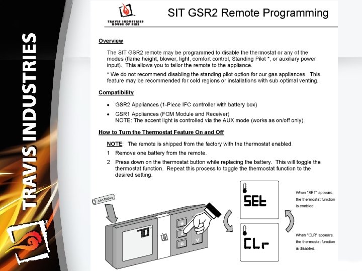
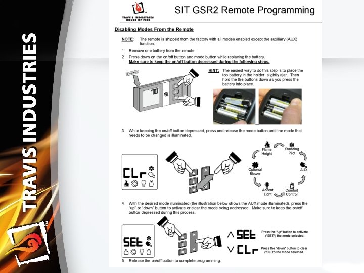
Remote Transmitter 250‐ 03262 Ø Ø Ø Ø Sends signal to receiver On/Off button Thermostat button Up and Down arrow key Mode button Used in upgraded GS 2 remote and GSR 2 units Compatible to work with GS 1 remote systems (250‐ 02711) Ø Accent light and blower adjustment Ø IPI/CPI activation Ø Amber back light
GSR 2 Remote Operation Warning
GSR 2 Remote Operation Remote Setup: • Verify the Switch is on “REMOTE”
GSR 2 Remote Operation Remote Setup: Ø Synchronize the Transmitter to the IFC § Press the PRG (Program) button on the battery box (IFC will beep 3 times). § Press the “ON” button on the transmitter (IFC will beep 3 times). • Clearing the System Memory • To clear the system memory, MAKE SURE GAS IS TURNED OFF TO THE APPLIANCE then press the PRG (Program) button for 10 seconds. The pilot will start to spark repeatedly, signifying all system memory has been cleared. The system will return to its original configuration: a remote will need to be synchronized; and, the system will operate under continuous pilot mode.
Green. Smart ‐ Lineage Ø 2009 Green. Smart 1 was introduced into all Travis Industries Gas Burning appliances Ø 2012 Green. Smart 2 was introduced as a new improved version of GS 1 Ø In June of 2012 it was noticed the performance of GS 1 & GS 2 wasn’t as good as the past. Ø It was discovered the manufacture of the GS system reduced the spark amptitude from 158 volts to 145 volts § The lowering of voltage by the vendor creates unforeseen reaction to the system as tested What did Travis Industries do?
GREENSMART ‐ Improvements Ø PSE Pilot Assembly (mid 2013) Ø Sheathing the Rectification Rod Wire (mid 2014) Ø Shepherds Hook Rectification Rod (beginning of 2015) Ø IFC & DFC Module Power Increased (end of 2014) Ø IFC & DFC Module Noise Silencing (Fall of 2015) Ø Minimized the use of Silicone (beginning of 2015) Ø Remote Control Signal Strength (mid 2015) Ø Component Testing (beginning of 2015) Ø IFC & DFC Module FFRT boards introduced (Fall of 2016)
PSE Pilot Assembly (mid 2013) w/ Sheathed Shepherds Hook Rectification Rod (2014/ 2015) Ø Original Pilot Assembly was a SIT assembly, designed for MV systems Ø PSE Pilot Assembly is designed for IPI systems, robust Pilot Assembly Ø Grounding the Pilot Assembly is extremely important for IPI systems Ø All Green. Smart Units can be upgraded to PSE the Pilot Assembly Ø Sheathing added to the Rectification Rod wire to cut down on external electrical interference Ø Shepherds Hook Rectification Rod gives Pilot Flame more surface contact, overcomes pilot flame drop out due to active pilots Note: Pilot Flame for IPI systems must be a continuous flame with no air gaps between the pilot hood and rectification rod in order for the control module to recognize pilot flame, this is known as pilot flame rectification.
IFC (GS 2) & DFC (GS 1) Module Power Increased (end of 2014) Ø Module Power has been sacrificed through Module Revision Changes throughout the years § This caused for pilot flame failure (loss of pilot flame rectification) due to low amount of power going through the rectification rod to the pilot hood. Ø Current Module Revisions, power has been increased to 200 milliamps § 50 more milliamps than the original best GS modules Ø Increased power allows for the Module to overcome restrictions in the pilot circuit. § Dirty or Compromised Pilot Hood § Dirty Rectification Rod § Partially broken Rectification Rod wire Ø Current Module Revision § DFC (GS 1) Revision 14 § IFC (GSB 2) Revision 6 § IFC (GSR 2) Revision 7 Continued…
IFC (GS 2) & DFC (GS 1) Improved FFRT Module (Fall of 2016) Ø Historically, IFC boards have a Flame Failure Response Time (FFRT) of 0. 8 seconds. – If the pilot left the flame sensor for longer than 0. 8 seconds the board made 3 attempts to re-light. – If no ignition was achieved the board would lock-out Ø “New Boards” have a FFRT of 5 seconds – If the pilot leaves the flame sensor for longer than 5 seconds, the board will not attempt to re-light. – The board will lock-out Ø New Part #’s – GS 1 DFC Module 250 -03824 – GSB 2 IFC Module 250 -03825 – GSR 2 IFC Module 250 -03826 Ø Replacement modules are being phased into inventory throughout the summer 2016 Ø New FFRT Modules are being phased into production units throughout the summer of 2016 Ø Module Revision #’s are starting back at “ 0”
Remote Control Signal Strength (mid 2015) Ø Customers with the New GSR 2 Wall Mount Remote Control were having difficulty operating there unit through the Remote Control Ø Travis’s Electrical Engineer found the Antenna was not putting out the correct amount of power to communicate with the IFC Module Ø Wall Mount Remote Controls have had the Antenna Power corrected to give full signal strength Ø Correct Remotes will either: § Have a label with the word “zero” inside the battery cover § OR, Be Revision 1 Wall Mount Remote Controls Note: Some fronts & faces can limit the communication to the IFC module, if this is the case an external antenna can be added to the IFC module for better reception.
Minimized use of Silicone (beginning of 2015) Ø Silicone Off Gas during burning § Creates a white film inside the appliance Ø Travis has changed from using Silicone as a sealant to using Mill Pack Ø Mill Pack has a higher temperature rating and does not off gas when exposed to high temperatures Ø Travis does not recommend using Silicone for gas appliance installation
Component Testing (beginning of 2015) Ø All Green. Smart Components are tested in house by Travis before being installed. Ø When Travis finds a problem with electrical components, that component goes through 100% testing/ inspection process until Travis Engineers are satisfied with results. § Example: All Wall Mount Remote Controls were being tested once Travis was aware of the communication problem. Now that the remote controls are performing to set standards, Travis test 10% of all remotes with less than 1% failure. Ø Travis has on staff Electrical Engineers that are setting the standards for the manufactured electrical components
IFC Safety Feature (GS 2) Ø Continuous Pilot Shutdown Safety Check § When Operating GS 2 units in the continuous pilot mode (CPI) every 24 hours the IFC will shut the pilot off then relight it to verify the pilot sensor is fully operational.
GS 1 Basic Green. Smart Flow of Power Ø Basic Ignition Flow 1. 2. 3. 4. 5. 6. 7. 8. Turn switch on to complete the circuit DFC module recognizes we want the unit to turn on DFC module begins spark ignition at the spark rod DFC module sends power to the pilot side of the valve (orange wire) Valve opens to supply fuel to pilot Pilot lights, pilot flame engulfs tip of flame rectification rod Flame rectification rod sends signal to DFC module that pilot lighting sequence is complete DFC module then does the following 1. 2. Sends signal to burner side of the valve to open and light the burner (green wire) Stops spark rod from sparking
GS 1 Basic Green. Smart Flow of Power Ø Comfort Control Operation 1. Comfort control switch is turned on 2. Comfort Control Valve opens as long as batteries in the battery tray are good 1. If batteries are not good the valve will not open 3. Comfort Control Valve is independent of the DFC module 4. Comfort Control operates the flow of gas to the rear burner 1. 2. When turned on, gas will flow to the rear burner When turned off, gas will stop flow to the rear burner
GS 1 Basic Green. Smart Flow of Power Ø Blower & Light Operation 1. Blower & Light Operation is independent from the DFC module. They each have individual rheostats that control operation and intensity. 2. They receive power directly from the incoming power source.
GS 1 Wiring Diagram (Base)
GS 1 Remote System Flow of Power Ø GS 1 Ignition Flow 1. 2. 3. 4. 5. 6. 7. 8. 9. Use remote control to turn unit on Receiver receives signal from remote to tell the unit to turn on Receiver sends a signal to the DFC module receives signal from receiver and begins spark ignition at the spark rod DFC module sends power to the pilot side of the valve (orange wire) Valve opens to supply fuel to pilot Pilot lights, pilot flame engulfs tip of flame rectification rod Flame rectification rod sends signal to DFC module that pilot lighting sequence is complete DFC module then does the following 1. 2. Sends signal to burner side of the valve to open and light the burner (green wire) Stops spark rod from sparking
GS 1 Remote System Flow of Power Ø Variable Flame Operation 1. Use remote control to adjust flame height 2. Receiver receives signal to adjust flame height 3. Receiver sends signal to Stepper Motor to adjust gas flow/ flame height to the burner
GS 1 Remote System Flow of Power Ø Comfort Control Operation 1. Use remote control to turn Comfort Control on/off 2. Receiver receives signal to turn operate Comfort Control 3. Receiver sends signal to the Comfort Control valve to turn Comfort Control on/off.
GS 1 Remote System Flow of Power Ø Blower Operation 1. Use remote control to turn on or adjust blower speed 2. Receiver receives signal to turn on blower or adjust blower speed 3. Receiver sends signal to Fan Control Module to turn on blower or adjust blower speed. 4. Fan Control Module will turn on or adjust blower accordingly Note- blower does not use a snap disc when using a GSR 1 system. Blower will turn on without time delay when operating manually through the remote control. When in thermostat mode the blower operates on a start up time delay and an off time delay.
GS 1 Remote System Flow of Power Ø Light Operation 1. Use remote control to turn on/off light 2. Receiver receives signal to turn on/off light 3. Receiver sends signal to Fan Control Module to turn on/off light 4. Fan Control Module will turn on/off light
GS 1 Wiring Diagram (Remote)
GS 2 Basic System Flow of Power Ø Basic Ignition Flow 1. 2. 3. 4. 5. 6. 7. 8. Turn switch on to complete the circuit IFC module recognizes we want the unit to turn on IFC module begins spark ignition at the spark rod IFC module sends power to the pilot side of the valve (orange wire) Valve opens to supply fuel to pilot Pilot lights, pilot flame engulfs tip of flame rectification rod Flame rectification rod sends signal to IFC module that pilot lighting sequence is complete IFC module then does the following 1. 2. Sends signal to burner side of the valve to open and light the burner (green wire) Stops spark rod from sparking
GS 2 Basic System Flow of Power Ø Comfort Control Operation 1. Comfort control switch is turned on 2. Comfort Control Valve opens as long as batteries in the battery tray are good 1. If batteries are not good the valve will not open 3. Comfort Control Valve is independent of the IFC module 4. Comfort Control operates the flow of gas to the rear burner 1. 2. When turned on, gas will flow to the rear burner When turned off, gas will stop flow to the rear burner
GS 2 Basic System Flow of Power Ø Blower & Light Operation § Blower & Light Operation is independent from the IFC module. They each have individual switches/rheostats that control operation and intensity. § They receive power directly from the incoming source. § The system features a 3 amp fuse for the lights and blower system individually.
GS 2 Wiring Diagram (Base)
GSR 2 Remote System Flow of Power Ø GSR 2 Ignition Flow 1. 2. 3. 4. 5. 6. 7. 8. Use remote control to turn unit on IFC module receives signal from unit to turn on unit IFC module begins spark ignition at the spark rod IFC module sends power to the pilot side of the valve (orange wire) Valve opens to supply fuel to pilot Pilot lights, pilot flame engulfs tip of flame rectification rod Flame rectification rod sends signal to IFC module that pilot lighting is complete IFC module then does the following 1. 2. Sends signal to the burner side of the valve to open and light the burner (green wire) Stops spark rod from sparking
GSR 2 Remote System Flow of Power Ø Variable Flame Operation 1. Use remote control to adjust flame height 2. IFC module receives signal from remote to adjust flame height 3. IFC module sends signal to stepper motor to adjust gas flow to burner
GSR 2 Remote System Flow of Power Ø Comfort Control Operation 1. Use remote control to turn Comfort Control on/off 2. IFC module receives signal from remote to operate comfort control valve 3. IFC module sends signal to comfort control valve to open/close
GSR 2 Remote System Flow of Power Ø Blower & Light Operation 1. Use remote control to turn on and adjust blower/light 2. IFC module receives signal from remote to operate the blower/light 3. IFC module sends signal to the blower/light to turn on/off and adjust intensity Note- blower does not use a snap disc when using a GSR 2 system. Blower will turn on without time delay when operating manually through the remote control. When in thermostat mode the blower operates on a start up time delay and an off time delay.
GSR 2 Wiring Diagram (Remote)
COMBUSTION OF GAS Ø Combustion Requirements The three necessary ingredients for combustion are: § Oxygen (air) § Fuel (gas) § Ignition (heat)
COMBUSTION OF GAS Controlled combustion Happens when there is a proper air/fuel ratio. The result is complete burning with a steady flame. Uncontrolled combustion, Explosion, occurs when there is an improper air/fuel ratio. The result is rapid burning with the creation of excessive pressure buildup.
Developing Trouble Shooting Mentality
Developing Trouble Shooting Mentality Ø ASK GOOD QUESTIONS § What did the fire look like when it went out? § How long did it burn before it went out? § How often does this happen? When making changes make one change at a time. Do not assume anything.
Problem Generating Categories Operator Error Appliance Inside Environment Outside Environment • Unrealistic • Defective components • Negative pressure conditions • Surrounding buildings, roof lines performance expectations • Improperation of appliance Mis-assembled/ installed Factory Field • Appliance placement & location Weather factors
Gas Pressure Ø What tool do you use to test gas pressure? Ø What is your incoming gas pressure supposed to be? § NG Appliances § LP Appliances Ø What is your outgoing gas pressure suppose to be? § NG Appliances § LP Appliances
Gas Pressure ‐ Affects ØWhat can be affected by incorrect Gas Pressure § Pilot Flame § Delayed Ignition § Post Ignition § Sooting § Flame Height § Overall Unit Operation § Heat Output § Component Longevity § Unit longevity
Gas Pressure‐Testing ØHow do you test incoming gas pressure? ØHow do you test outgoing gas pressure? ØHow can incorrect gas pressure affect your pilot light?
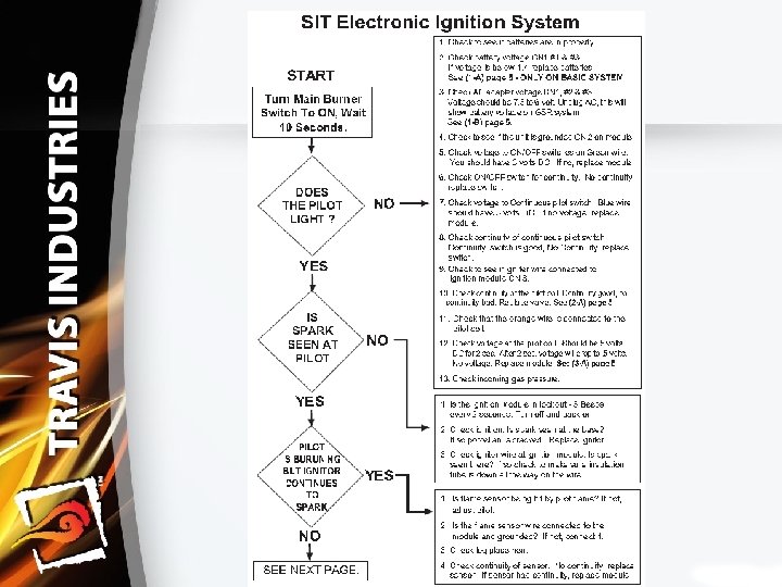
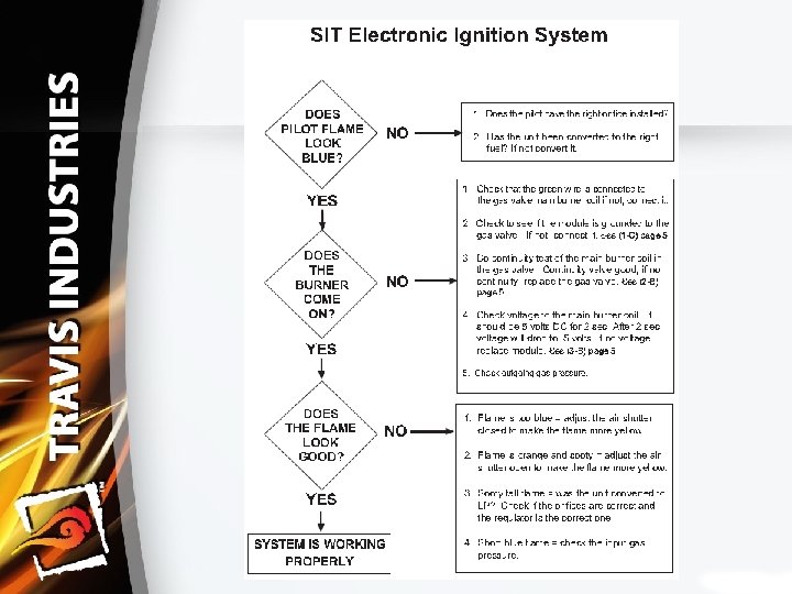
Troubleshooting Green. Smart System SIT IPI (intermittent pilot ignition) System
DFC Audible Explanation (GS 1) Ø Audible Beep § One Audible Beep – Low Battery in either Battery Box or Receiver § Two Audible Beeps – Parasitic Pilot Flame § Three Audible Beeps – System Lock Out
IFC Light Explanation (GS 2) Ø Yellow Light § Must be on to sync remote Ø Red Light § One Flash – initial power up and low battery § Two Flashes – parasitic pilot flame § Three Flashes – lock out
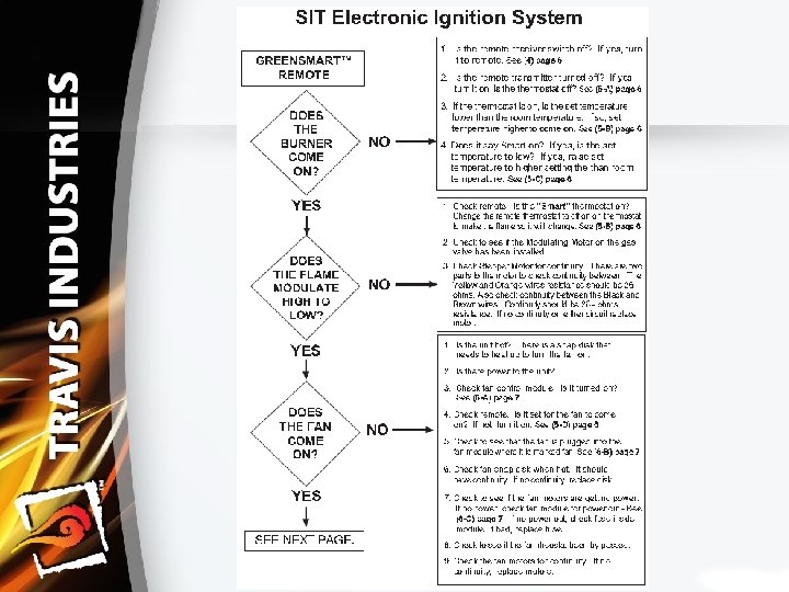
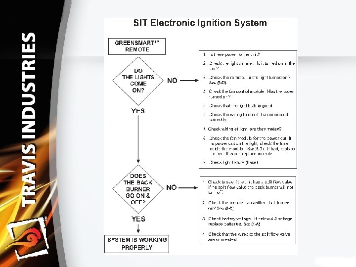
GREENSMART 1 Troubleshooting
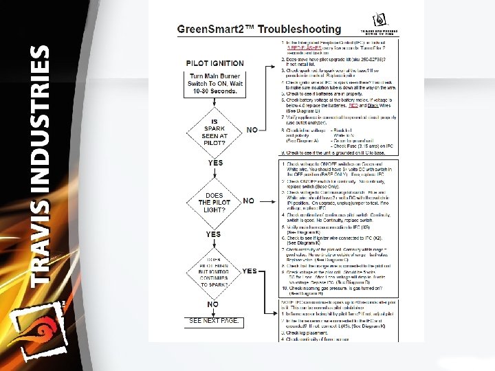
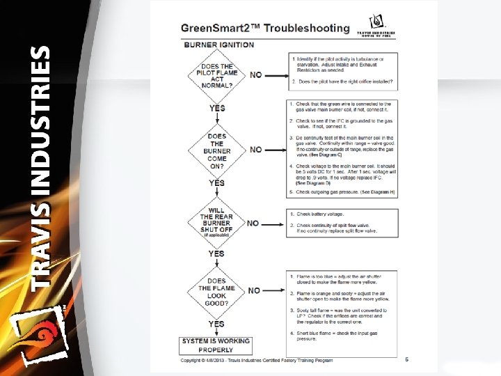
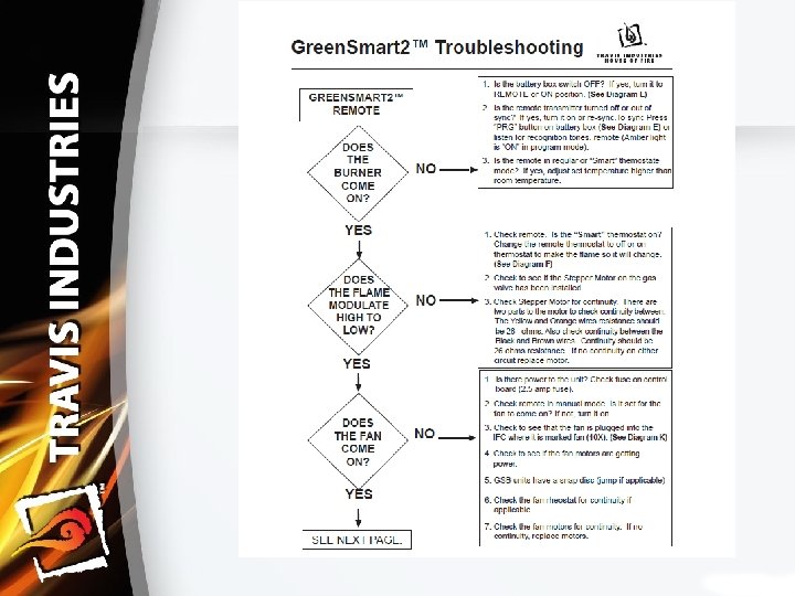
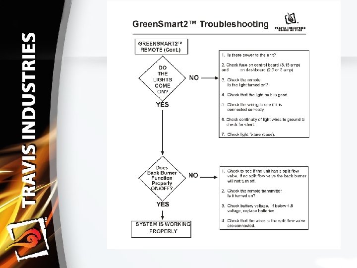
GREENSMART 2 Troubleshooting