
Stone media TF design Example 1 Calculate the


- Slides: 20
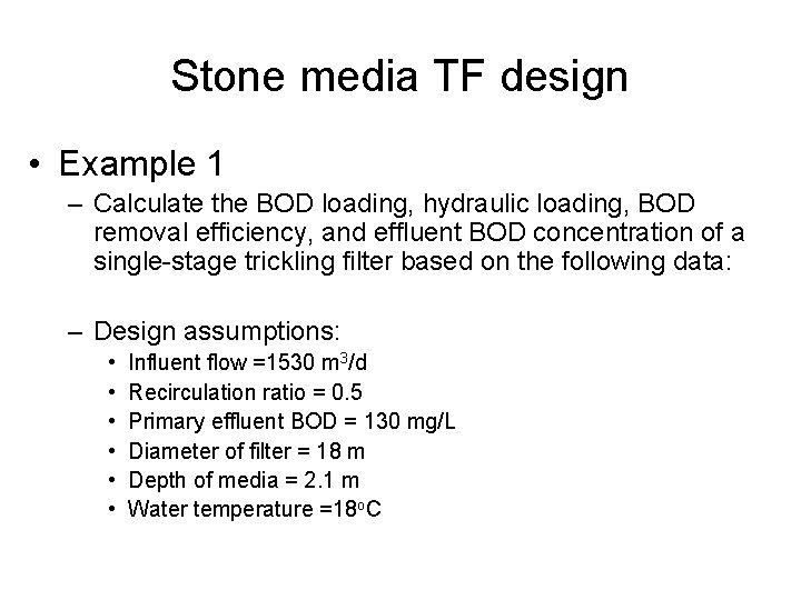
Stone media TF design • Example 1 – Calculate the BOD loading, hydraulic loading, BOD removal efficiency, and effluent BOD concentration of a single-stage trickling filter based on the following data: – Design assumptions: • • • Influent flow =1530 m 3/d Recirculation ratio = 0. 5 Primary effluent BOD = 130 mg/L Diameter of filter = 18 m Depth of media = 2. 1 m Water temperature =18 o. C
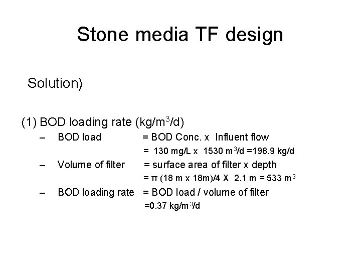
Stone media TF design Solution) (1) BOD loading rate (kg/m 3/d) – BOD load = BOD Conc. x Influent flow = 130 mg/L x 1530 m 3/d =198. 9 kg/d – Volume of filter = surface area of filter x depth = π (18 m x 18 m)/4 X 2. 1 m = 533 m 3 – BOD loading rate = BOD load / volume of filter =0. 37 kg/m 3/d
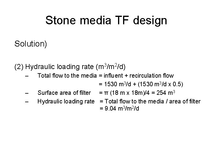
Stone media TF design Solution) (2) Hydraulic loading rate (m 3/m 2/d) – – – Total flow to the media = influent + recirculation flow = 1530 m 3/d + (1530 m 3/d x 0. 5) Surface area of filter = π (18 m x 18 m)/4 = 254 m 3 Hydraulic loading rate = Total flow to the media / area of filter = 9. 04 m 3/m 2/d
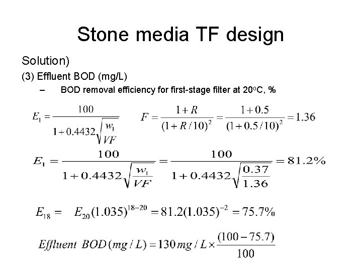
Stone media TF design Solution) (3) Effluent BOD (mg/L) – BOD removal efficiency for first-stage filter at 20 o. C, %
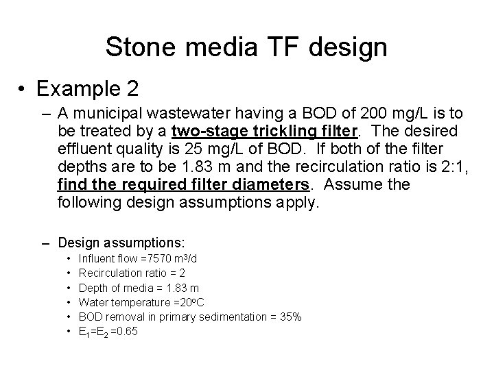
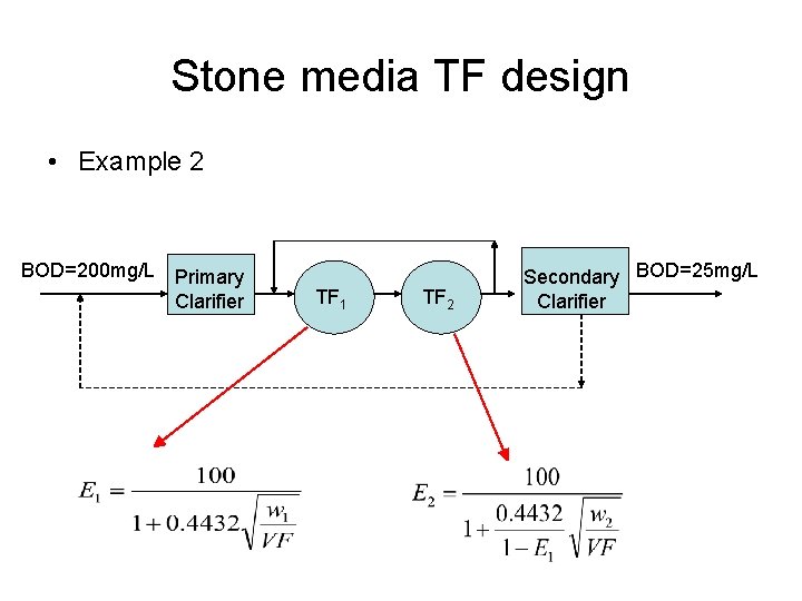
Stone media TF design • Example 2 – A municipal wastewater having a BOD of 200 mg/L is to be treated by a two-stage trickling filter. The desired effluent quality is 25 mg/L of BOD. If both of the filter depths are to be 1. 83 m and the recirculation ratio is 2: 1, find the required filter diameters. Assume the following design assumptions apply. – Design assumptions: • • • Influent flow =7570 m 3/d Recirculation ratio = 2 Depth of media = 1. 83 m Water temperature =20 o. C BOD removal in primary sedimentation = 35% E 1=E 2 =0. 65
Stone media TF design • Example 2 BOD=200 mg/L Primary Clarifier TF 1 TF 2 Secondary BOD=25 mg/L Clarifier
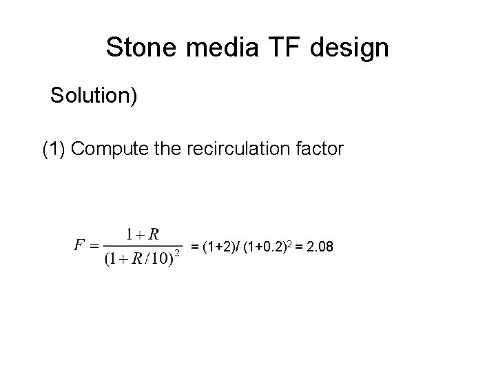
Stone media TF design Solution) (1) Compute the recirculation factor = (1+2)/ (1+0. 2)2 = 2. 08
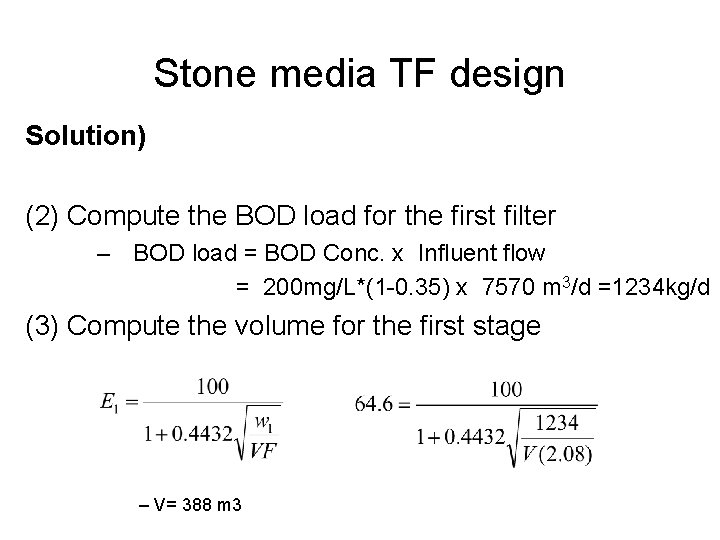
Stone media TF design Solution) (2) Compute the BOD load for the first filter – BOD load = BOD Conc. x Influent flow = 200 mg/L*(1 -0. 35) x 7570 m 3/d =1234 kg/d (3) Compute the volume for the first stage – V= 388 m 3
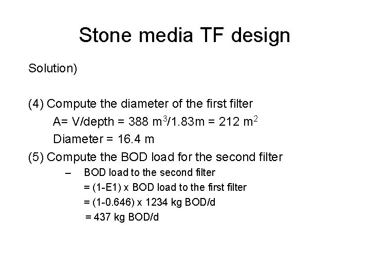
Stone media TF design Solution) (4) Compute the diameter of the first filter A= V/depth = 388 m 3/1. 83 m = 212 m 2 Diameter = 16. 4 m (5) Compute the BOD load for the second filter – BOD load to the second filter = (1 -E 1) x BOD load to the first filter = (1 -0. 646) x 1234 kg BOD/d = 437 kg BOD/d
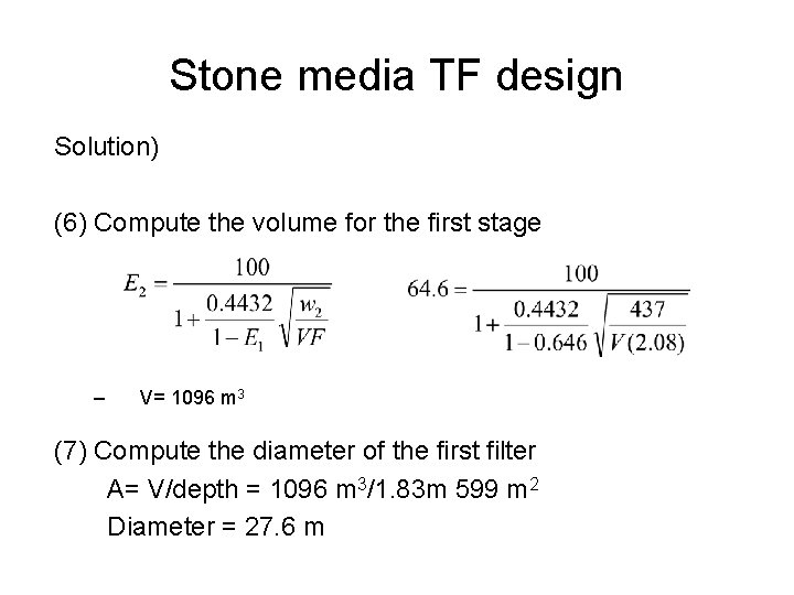
Stone media TF design Solution) (6) Compute the volume for the first stage – V= 1096 m 3 (7) Compute the diameter of the first filter A= V/depth = 1096 m 3/1. 83 m 599 m 2 Diameter = 27. 6 m
Stone media TF design Solution) (8) Compute the BOD loading to each filter (9) Compute the hydraulic loading to each filter
Plastic media
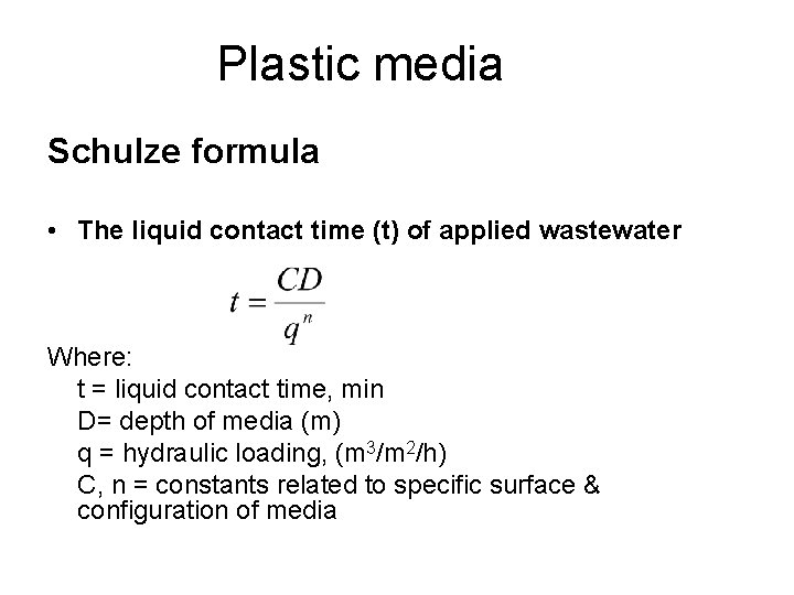
Plastic media Schulze formula • The liquid contact time (t) of applied wastewater Where: t = liquid contact time, min D= depth of media (m) q = hydraulic loading, (m 3/m 2/h) C, n = constants related to specific surface & configuration of media
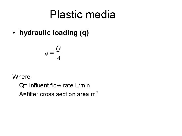
Plastic media • hydraulic loading (q) Where: Q= influent flow rate L/min A=filter cross section area m 2
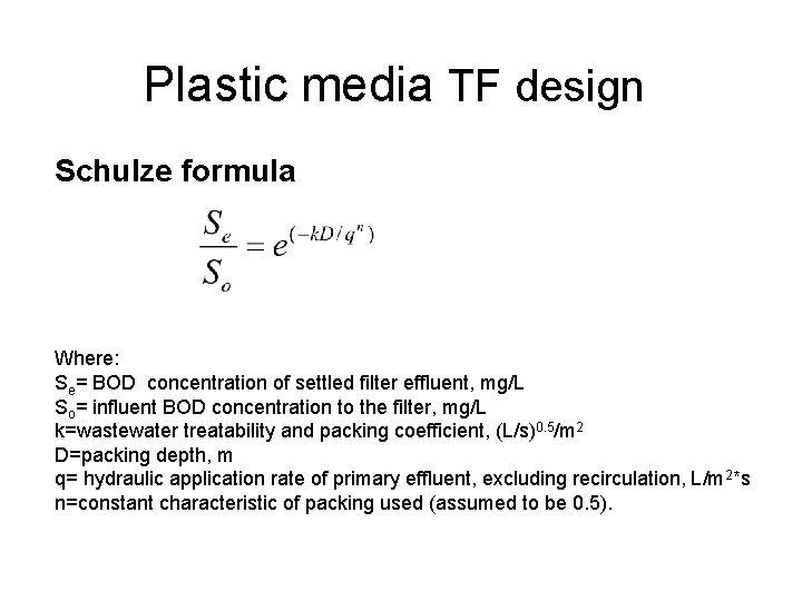
Plastic media TF design Schulze formula Where: Se= BOD concentration of settled filter effluent, mg/L So= influent BOD concentration to the filter, mg/L k=wastewater treatability and packing coefficient, (L/s)0. 5/m 2 D=packing depth, m q= hydraulic application rate of primary effluent, excluding recirculation, L/m 2*s n=constant characteristic of packing used (assumed to be 0. 5).
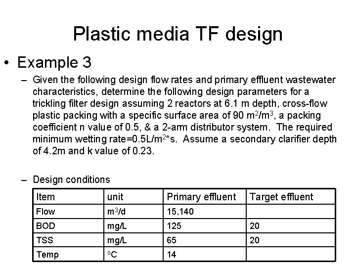
Plastic media TF design • Example 3 – Given the following design flow rates and primary effluent wastewater characteristics, determine the following design parameters for a trickling filter design assuming 2 reactors at 6. 1 m depth, cross-flow plastic packing with a specific surface area of 90 m 2/m 3, a packing coefficient n value of 0. 5, & a 2 -arm distributor system. The required minimum wetting rate=0. 5 L/m 2*s. Assume a secondary clarifier depth of 4. 2 m and k value of 0. 23. – Design conditions Item unit Primary effluent Target effluent Flow m 3/d 15, 140 BOD mg/L 125 20 TSS mg/L 65 20 Temp o. C 14
Plastic media TF design • Example 3 – Calculate the followings • Diameter of TF, m • Volume of packing require, m 3
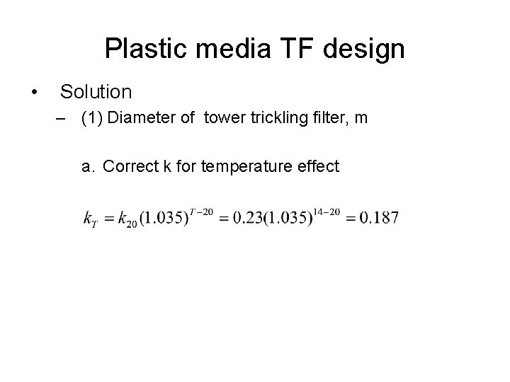
Plastic media TF design • Solution – (1) Diameter of tower trickling filter, m a. Correct k for temperature effect
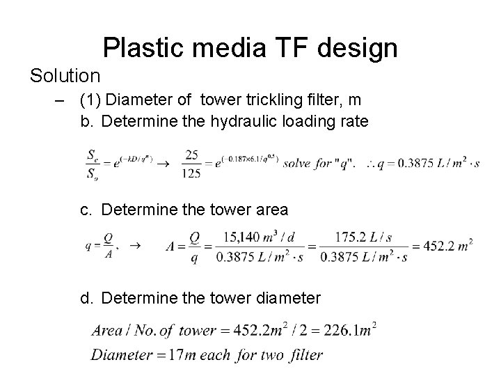
Plastic media TF design Solution – (1) Diameter of tower trickling filter, m b. Determine the hydraulic loading rate c. Determine the tower area d. Determine the tower diameter