Steve Grive Head of Information Technology Services Session


")


 FR 1 FR")


- Slides: 83
Steve Grive Head of Information Technology Services Session 1 Technology framework overview
IT Services Operational, Service and Strategic Overview The purpose of the presentation is to articulate: - • the systems environment and its components • the ‘owners’ of elements of the environment • supporting the student experience
Operational, Service and Support Framework OPERATIONAL SERVICE & SUPPORT USER INTERFACE LAYER NETWORK LAYER PHYSICAL LAYER CUSTOMER SERVICE & REPORTING SERVER/HARDWARE LAYER IT CONTINUITY AND DISASTER RECOVERY LAYER SECURITY BACKUP & MONITORING TECHNICAL PLANNING DATABASE PROJECT MANAGEMENT OPERATING SYSTEM CONFIGURATION CONTROL APPLICATION LAYER
BUSINESS APPLICATIONS UWEOnline Virtual Learning Environment SYLLABUS+ Timetabling Online Applications UCAS Interface ACES Admissions, Clearing and Enquiry System IRIS/LARES Admissions and Accommodation AGRESSO Finance ISIS Management Information ALUMNI Graduate Students SAP/HR Personnel and Payroll
Web Enabled APPLICATIONS Student Portal UWEOnline Virtual Learning Environment Online Enquiry On-line and Application Tutorial Group Photo Lists Applications IRIS/LARES Admissions and Online Accommodation Student Records Staff SYLLABUS+ Portal Timetabling ISIS Management Online Information Timetables Web-Mail Core Applications Student E-Mail
The layered model SAP/HR Personnel and Payroll
Operational, Service and Support Framework OPERATIONAL USER INTERFACE LAYER APPLICATION LAYER OPERATING SYSTEM DATABASE BACKUP & MONITORING LAYER SERVER/HARDWARE LAYER NETWORK LAYER PHYSICAL LAYER
Operational, Service and Support Framework OPERATIONAL USER INTERFACE LAYER APPLICATION LAYER OPERATING SYSTEM DATABASE BACKUP & MONITORING LAYER SERVER/HARDWARE LAYER NETWORK LAYER PHYSICAL LAYER
IT Continuity and Disaster Recovery Machine Rooms and Network Stations FR 1 – Main machine/network room in B block FR 2 – DMZ machine room in B block FR 3 – Second machine/network room in Botetourt House FR 4 – Library Way Station (in D block)
Machine rooms FR 4 FR 1/ FR 2 FR 3 Bristol University
Operational, Service and Support Framework OPERATIONAL Switch USER INTERFACE LAYER APPLICATION LAYER Router OPERATING SYSTEM DATABASE BACKUP & MONITORING LAYER SERVER/HARDWARE LAYER NETWORK LAYER PHYSICAL LAYER Switch Physical Network LAN WAN SUPERJANET
Main Network Equipment in FR 1
Network Cabinets in Second Machine Room FR 3 Half of the network boundary equipment Cisco 6513 part of the campus backbone
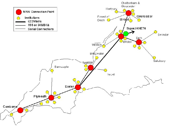
IT Continuity and Disaster Recovery Remote UWE Sites Bristol University
Remote UWE Sites Continuity and DR Objectives – Phase 1 University Bristol of University
Operational, Service and Support Framework Server Farm OPERATIONAL USER INTERFACE LAYER APPLICATION LAYER OPERATING SYSTEM DATABASE 1 2 3 4 SAP Servers BACKUP & MONITORING LAYER 1 2 3 SERVER/HARDWARE LAYER NETWORK LAYER PHYSICAL LAYER Server Hardware
Server hardware
Server hardware location design Rack 1 – FR 3 Rack 1 – FR 1 Production Test Development Rack 2 – FR 1 Building hardware continuity into the various system landscapes, careful consideration for location of servers Reduces risk of loss of all hardware in the case of destruction Reduces risk through loss of power to server rack, whole room or site Contributes towards our Disaster Recovery and Continuity Strategy FR 1 FR 3
Operational, Service and Support Framework OPERATIONAL Same for all servers USER INTERFACE LAYER 1 2 3 4 APPLICATION LAYER OPERATING SYSTEM DATABASE BACKUP & MONITORING LAYER SERVER/HARDWARE LAYER System Monitoring Backups NETWORK LAYER PHYSICAL LAYER Operating System
Operational, Service and Support Framework OPERATIONAL SAP Servers only USER INTERFACE LAYER APPLICATION LAYER Application OPERATING SYSTEM Database DATABASE BACKUP & MONITORING LAYER SERVER/HARDWARE LAYER System Monitoring Backups NETWORK LAYER PHYSICAL LAYER Operating System
Operational, Service and Support Framework OPERATIONAL Server Farm only USER INTERFACE LAYER APPLICATION LAYER OPERATING SYSTEM SAP Graphical User Interface DATABASE BACKUP & MONITORING LAYER SERVER/HARDWARE LAYER System Monitoring Backups NETWORK LAYER PHYSICAL LAYER Operating System
Operational Service Framework OPERATIONAL USER INTERFACE LAYER APPLICATION LAYER OPERATING SYSTEM DATABASE LAYER DATABASE BACKUP & MONITORING OPERATING SYSTEM LAYER SERVER/HARDWARE LAYER NETWORK LAYER PHYSICAL LAYER SAP Graphical User Interface Application Database System Monitoring Backups Operating System Server Hardware Physical Network Physical Room: FR 1/FR 2/FR 3/FR 4
OPERATIONAL USER INTERFACE LAYER APPLICATION LAYER Emphasis of Ownership Customer Emphasis IT Services/Faculty and/or Central Services OPERATING SYSTEM DATABASE LAYER DATABASE BACKUP & MONITORING OPERATING SYSTEM LAYER IT Services SERVER/HARDWARE LAYER NETWORK LAYER PHYSICAL LAYER IT Services Emphasis
The simple picture
PC/ Winterm Server Network Printer
Start User oflogs-in the day Network Server responds
Connection established Network
SAPRequest Starts running login toon SAP server Network
SAP Responds Network
Request to print pay-slips Network
Server initiates printing Network Printer responds
Pay-slips are printed and sent off Network
User logs-off Network
User goes home Network
Overnight backups start Network
The real picture How does it work? (the login process)
! u o Y re a e er h Switch Where am I on the network? and What is my name? Router DNS/ DHCP Switch Router The routers and switches are programmed to find the DHCP server which has the answers. You are allocated an IP address e. g. 164. 11. 56. 134. The routers and switches also know how to find their way back to you to tell you.
User log-in? Switch Server Farm Router Switch Where is the server farm? 1 2 3 4 DNS/ DHCP Ask the DNS server! Switch Router Farm is now visible!
User log-in Switch Router DNS/ DHCP Switch Security Controller Router Server Farm Switch 1 2 3 4 User login And so the request processsent continues…. Farm asks DNS to locate the security controller Until the full network DNS replies and servers are Security controller available and the now in sight applications are running Login request is authenticated
Printer Server Switch Router Switch Server Farm 1 2 3 4 DNS/ DHCP Switch Router SAP Servers Switch Backups Domain Controller 1 2 3
Printer Server Switch Router Switch Server Farm 1 2 3 4 DNS/ DHCP ISDN Router Switch Router SAP Landscape Backups Domain Controller Modem Switch 1 2 3
Private UWE Domain Staff That’s this bit
Public Domain Private UWE Domain Rackhay Staff RAS ISDN/ Modem WWW/ MAN/ VPN UWE Domain Router External DNS Students Including new village Faculty DMZ IT Service DMZ
Steve Grive Head of Information Technology Services Session 2 Service framework overview
Operational, Service and Support Framework OPERATIONAL SERVICE & SUPPORT USER INTERFACE LAYER NETWORK LAYER PHYSICAL LAYER DISASTER RECOVERY SERVER/HARDWARE LAYER CONFIGURATION CONTROL LAYER SECURITY BACKUP & MONITORING TECHNICAL PLANNING DATABASE PROJECT MANAGEMENT OPERATING SYSTEM CUSTOMER SERVICE & REPORTING APPLICATION LAYER
Operational, Service and Support Framework SERVICE & SUPPORT CUSTOMER SERVICE & REPORTING IT CONTINUITY AND DISASTER RECOVERY CONFIGURATION CONTROL SECURITY TECHNICAL PLANNING PROJECT MANAGEMENT
Operational, Service and Support Framework SERVICE & SUPPORT CUSTOMER SERVICE & REPORTING IT CONTINUITY AND DISASTER RECOVERY CONFIGURATION CONTROL SECURITY TECHNICAL PLANNING PROJECT MANAGEMENT
Operational, Service and Support Framework ITS / UWE PROJECT MANAGEMENT FRAMEWORK Corporate or Programme Management Directing a Project Starting up a Project Initiating a Project Controlling a stage Managing Product Delivery Planning Managing Stage Boundaries Closing a project Post Project Activities
Operational, Service and Support Framework System Landscapes SERVICE & SUPPORT SERVICE REPORTING 1 2 3 DISASTER RECOVERY CONFIGURATION CONTROL Distinct areas for: • Development • Testing • Production SECURITY TECHNICAL PLANNING PROJECT MANAGEMENT
SAP Landscape and configuration control Development Production server farm Test Configuration Control 1 2 3 4 Terminal Servers Application and Database Servers Configuration Control Development Configuration Control QAS Production
Operational, Service and Support Framework Operational Framework • • Responsibilities clear System configuration fully documented • Adoption ® of ITIL Configuration control • IT Information Library Ongoing testing • Service Level Agreements agreed co-managed between users and IT services through User Groups • SERVICE & SUPPORT Procedures defined SERVICE REPORTING DISASTER RECOVERY CONFIGURATION CONTROL SECURITY TECHNICAL PLANNING PROJECT MANAGEMENT
Operational, Service and Support Framework Programme of work for ongoing IT Service Continuity and Disaster Recovery Established Multiple machine rooms and triangulated network backbone established SERVICE & SUPPORT SERVICE REPORTING IT CONTINUITY AND DISASTER RECOVERY CONFIGURATION CONTROL SECURITY Resilience encapsulated within system landscapes is now being extended into overall infrastructure TECHNICAL PLANNING PROJECT MANAGEMENT
IT Services Strategy and Objectives Continuity and Disaster Recovery Virtualisation Stability, Reliability and Availability Supporting the Student Experience
IT Services Strategy and Objectives Continuity and Disaster Recovery Phase 1 - complete Phase 2 - Service Continuity Phase 3 - Data Continuity
Remote UWE Sites Continuity and DR Objectives – Phase 1 University Bristol of University
IT Services Strategy and Objectives Continuity and Disaster Recovery Phase 1 - complete Phase 2 - Service Continuity Phase 3 - Data Continuity
Continuity and DR Objectives – Phase 2 - Service Continuity OPERATIONAL USER INTERFACE LAYER SAP Graphical User Interface APPLICATION LAYER Outlook Excel Word OPERATING SYSTEM DATABASE BACKUP & MONITORING Integrated Desktop LAYER SERVER/HARDWARE LAYER NETWORK LAYER PHYSICAL LAYER Printer Server Switch Server Farm
Service Register - Matrix UNIX End-User Layer Application Layer Operational Layer Back office Layer Resource Layer OS Layer Hardware Layer Network Layer Physical Layer MICROSOFT NETWORK
Service Register - Pulls all of this together into a single view
IT Services Strategy and Objectives Continuity and Disaster Recovery Phase 1 - complete Phase 2 - Service Continuity Phase 3 - Data Continuity
Continuity and DR Objectives – Phase 2 - Data Resilience Current Data Storage Production Backups Production Test • JBODS are tied to the If the Production system and its specific becomes unavailable then … purpose so move with the systems FR 1 • Systems have … Test Server can be data • Systems areseparate backed-up storage called JBODS recovered as the Independently. production system. FR 3
Continuity and DR Objectives – Phase 2 - Data Resilience New System - Storage Area Network • Highly resilient data storage • Independent of any particular system • UWE now has two of these
Using Storage Area networks for Resilience Test Production Replicate data (real-time) FR 1 FR 3
IT Services Strategy and Objectives Virtualisation What goes around, comes around…
Virtualisation Virtualization was first introduced in the 1960 s to allow partitioning of large, mainframe hardware -- a scarce and expensive resource.
Virtualisation Over time, minicomputers and PCs provided a more efficient, affordable way to distribute processing power, so by the 1980 s, virtualization was no longer widely employed.
Virtualisation In the 1990 s, researchers began to see how virtualization could solve some of the problems associated with the proliferation of less expensive hardware, including: - Underutilization (15 -20%) - escalating management costs (250+ servers) - vulnerability (complexity) ‘Thin’ Client In 2000 UWE virtualised PC’s Server Farms Virtual PCs ‘Thin’ Client
Virtualisation: The next stage Virtualization is an abstract ‘layer’ that decouples physical hardware from operating systems and also decouples physical data storage from servers and applications running on them. Enterprise Servers (Virtualisation Layer) Enterprise Storage (SAN)
Virtualisation… Virtual Server … allows multiple virtual machines, with heterogeneous operating systems to run in isolation, side-by-side on the same physical machine. Enterprise Servers (Virtualisation Layer) Enterprise Storage (SAN)
Virtualisation Virtual Server Applications Operating System Each virtual server has its own set of virtual hardware (e. g. , RAM, CPU, etc. ) upon which an operating system and applications are loaded. Enterprise Servers (Virtualisation Layer) Enterprise Storage (SAN)
Virtualisation Virtual Server Applications Operating System The operating system sees a consistent, normalized set of hardware regardless of the actual physical hardware components. Enterprise Servers (Virtualisation Layer) Enterprise Storage (SAN)
Virtualisation Virtual servers are encapsulated into files…. Virtual Server …. making it possible to rapidly save, copy Enterprise Servers (Virtualisation Layer) Enterprise Storage (SAN)
Virtualisation Virtual servers are encapsulated into files…. Virtual Server Virtual Server …. making it possible to rapidly save, copy and provision a virtual server. Enterprise Servers (Virtualisation Layer) Enterprise Storage (SAN)
Virtualisation Virtual Server Virtual Server Full systems (fully configured applications, operating systems, BIOS and virtual hardware) can be moved, within seconds, from one physical server to another for zero-downtime maintenance and continuous workload consolidation. Enterprise Servers (Virtualisation Layer) Enterprise Storage (SAN)
Virtualisation Enables greater IT resource utilization and flexibility to the entire architecture dependent upon needs of the business. Virtual Server Virtual Server - Servers only set up when required - Applications can be given greater capacity just by removing unutilized servers and/or creating bigger virtual servers Enterprise Servers (Virtualisation Layer) Enterprise Storage (SAN)
IT Services Strategy and Objectives Supporting the Student Experience
UWE Online is available 24 X 7 for 365 days a year and use of the system almost doubles each year, as per the statistics below: UWE Online System Architecture 2002 Separate Application Database Servers implemented 2004 Additional Failover Application Server & load balancing implemented. UWE Online comparative ‘hits’ 2005 - 2006 Clustered Database Servers and Two additional Application Servers added.
Student Desktop Services Drop in Centre in 1 E 007 • Wireless installation • Student computing advice Computer availability in Student labs Displays in real time Wireless connectivity Competitive priced Student Laptops: • Laptop Clinics • Virus software promoted Services Block P 2 P Traffic • Res Net & Net Plus advice Introducing Web Cam & MSN soon • Late evening opening until 20. 45 Mon – Fri Voice over IP (Vo. IP) • Focus on students only Approx 1, 800 desktops and 4, 200 study bedrooms supported daily
Computer Availability – Student Labs Trial with student lab occupancy software How many machines in use, how many available If successful: Display around Campuses possibly in receptions Directs students for better utilisation of equipment Should help with access to computing
• • • The portal provides web-based access to a range of University services It emphasises services for students and online administration These are based on an increasing number of channels: Student Portal Syllabus Plus (Timetable) Student Record data: • Personal details • Marks • Academic record • • • E Mail Content from and links to UWE-online and coursework submission Successful proof-of-concept completed 2004 Pilot completed in 2005 -2006 in HSC with c. 500+ students All students from Feb. 2007 with on-line registration and fee payment from September 2007 On-line registration and fee payment