Stereoscopic Models and Plotting Stereoscopic Viewing Stereoscopic viewing


 Mirror Stereoscope The eye base is increased by a system of mirrors Thus,")


 Or measure in stereo using a parallax bar. Put the photos")

 = (D")


- Slides: 42
Stereoscopic Models and Plotting
Stereoscopic Viewing “Stereoscopic viewing is the way the depth perception of the objects through BINOCULAR vision with much greater accuracy”. ● ﺭﺅﻴﻪ ﺍﻟﺒﻌﺪ ﺍﻟﺜﺎﻟﺚ ﻭ ﺍﻻﺣﺴﺎﺱ ﻭ ﻗﻴﺎﺱ ﺍﻟﻌﻤﻖ ● Conditions for seeing the third dimension using two photos: – Two photos – Taken from two different positions – Seen SEPARATELY. each eye see one image. § In photogrammetry, we imitate “ ”ﻧﻘﻠﺪ and deceive our brains ●
Stereoscopic Viewing • How do we see in Stereo? • The theory of stereoscopic viewing and parallactic angles • Seeing in stereo makes it possible to measure Z in addition to X and Y from two overlapping photos, since they provide stereovision in the overlap area. • The two photos are called: “a stereo pair”.
Principle of the Floating Mark ﺍﻟﻨﻘﻄﻪ ﺍﻟﻄﺎﻓﻴﻪ • The measuring index in stereo is called a floating mark. • A dot, or half a dot, that when rests on a location in the stereo model, the observer sees one mark instead of two • The apparent height (Z) of the mark is related to the x separation of the point in photos, its parallax.
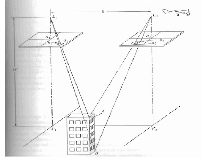
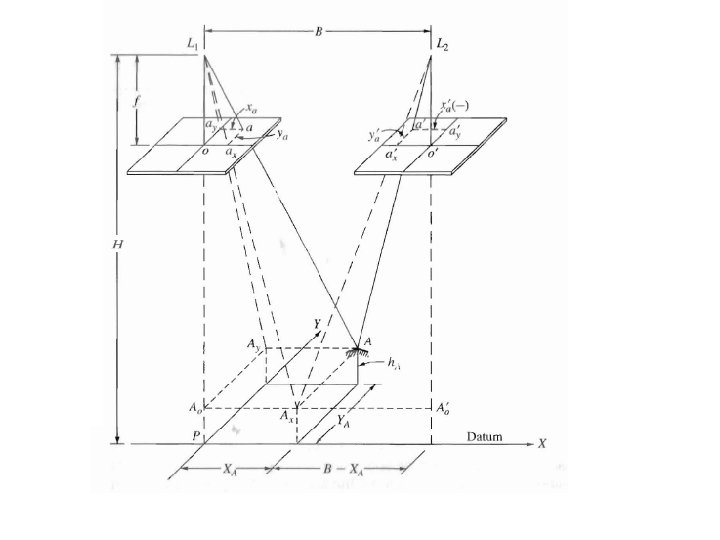
Stereoscopic Parallax • The apparent displacement of the position of an object wrt a frame of reference due to a shift in the point of observation, try it. There is a shift in relative position of the same object (your finger for example” if you notice the right and left eye views of it. • The shift is along the line that connects the exposure stations, your eye-base for example, . • In aerial photogrammetry, that shift is along the flying line What is (x) ? “the. Parallax air base L 1 L 2” get the flying height = p = x - x 1 or point elevation • The closer the object to the frame, the larger the shift for ground so coordinates the samegetshift, parallax is a function Bf of height. • Parallax equations: B B X= p x Y= p y H-h = P
- Parallax p = x – x 1 - LL 1 a’ a 1’ and A’ L L 1 are similar triangles, then P / B = f / (H-h) , or P = f B / (H-h) Also, since the scale = f / (H-h) then. , Scale = P / B
Stereoscopic Parallax equations: Parallax = p = x left – x 1 right= x - x 1 Bf H-h = P B X= p x get the flying height or point elevation Y= B py get ground coordinates Therefore, h =H- Bf P The bigger the parallax, the higher the point
Remarks • The bigger the parallax, the higher the point • The higher the point, the bigger the parallax • X parallax is useful, it can be used to determine elevations, Y parallax is not useful and must be removed for clear stereo vision.
Stereoscopes • Simple instruments to enable stereo vision and magnification: see each photo separately through a lens • They can be: a) Pocket stereo scopes - the simplest – Note that because of the small base, the photographs must be On top of each other. – Does not enable viewing of the entire stereo coverage at the same time.
For any stereo scope, to provide a stereo model, the two photos must cover a common area taken from two different locations, in addition, the scale of the two photographs must be equal and the line that connects the center of the photos should be in the direction of the air base This part of stereo coverage cannot be seen unless if the photographs are separated more.
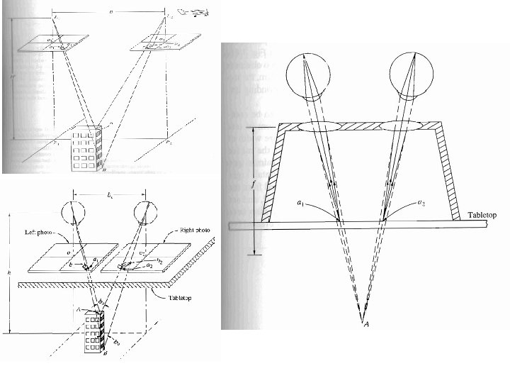
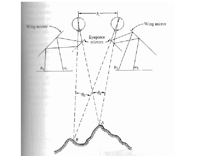
b) Mirror Stereoscope The eye base is increased by a system of mirrors Thus, the entire stereo model can be viewed. In general, the eyebase, the direction of flight, and the line joining the centers of the lenses should be parallel.
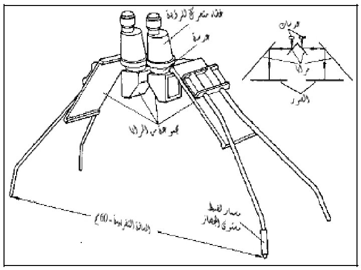
Height determination using a Parallax Bar The parallax bar is a measuring device to measure the x parallax of points in a fast and precise manner.
• Since x parallax is a function of relief or heights of points above datum, elevations of points can be computed by measuring their parallax. • Other values can also be derived if unknown such as the flying height, or air base. • To measure parallax of a point you can : a) Either measure in mono: measure the value of the x coordinate of the point on each photograph and subtract the left from the right value. For example, if point a appears on Left and right photos then: pa = xa. L – xar
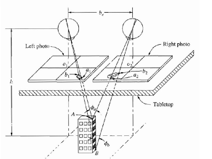
• b) Or measure in stereo using a parallax bar. Put the photos on a table under a stereoscope, move them right and left up and down until you see comfortably in stereo, in this case: air base B as photo base b: o 1 o 2, and the center of the lenses of the device must be in the same direction
L Photo base b R Photo base b’ The image of each photo nadir, P. P in a vertical photo (o 1 and o 2’)appears on the other photo Parallax of b = D – db = xb – xb’ note that xb’ is negative)
C pa = xa – xa’ = D – (C – ra) = (D – C) + ra Assume that k = (D – C) Since D and C are constants, then k is a constant, called the parallax bar constant for the setup, then, pa = k + r
• To calculate the parallax of a point, you measure the value r for it with a parallax bar and multiply it by the constant K, you can do that in stereo for a set of points in few minutes. • Now, how to compute the constant K? ? • It is computed only once by measuring the parallax of two point monoscopically by measuring their x coordinate on each photo and subtract: p = x- x 1 • Now measure the value (r) for each point and apply the equation: k = p – r • You get two values for k, take the average. • You can use photo centers for this process since the x value of each one on its own photograph is 0, you just need to measure its x value on the other photo
• Summary of computation of parallax using a parallax bar: • Without the bar, using a precise ruler measure the values of x of two points a and b on both photos, well distinctive points • Calculate the parallax of the two points, where: pa = xa – xa’ and pb = yb – yb’ • Use the parallax bar to measure ra and rb fro the same points. • Compute k 1 = pa – ra and k 2 = pb – rb • K is the average = (k 1 + k 2 )/2 • For any point measure r with the bar and multiply by k to get the parallax
Example A pair of overlapping vertical photographs were taken from a flying height of 4045 feet with a 152. 4 mm focal length camera. The air base was 1280 feet and parallax bar readings of 12. 57 and 13. 04 mm were obtained with the floating mark set on principal points (ol) and (o 2) respectively. If b and b‘ ( left and right photo bases) were measured as 93. 73 and 93. 30 mm. Parallax bar readings of 10. 96 and 15. 27 mm were taken on points A and B. Also the x and y photo coordinates of points A and B were Xa = 53. 41 mm, Ya = 50. 84 mm , Xb= 88. 92 mm and Yb=46. 69 mm Calculate the elevations of points A and B and the horizontal distance between them.
Solution: Parallax of Point 01=Po 1 = b'= 93. 30 mm. Parallax of Point O 2= Po 2 = b = 93. 73 mm Equation of parallax bar: P =K+r K = P - r For point 01 : For Point 02 : k 1=Po 1 - ro 1=93. 30 -12. 57 = 80. 73 mm k 2=P 02 -r 02=93. 73 -13. 04 = 80. 69 mm For point a: Pa = k + ra= 80. 71+ 10. 96= 9 l. 67 mm. For point b : Pb = k + rb= 80. 71+ 15. 27= 95. 98 mm ,
Elevations of points:
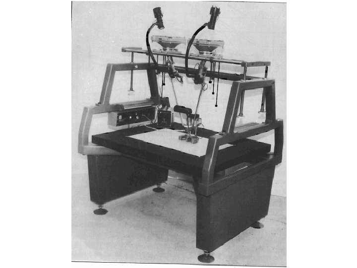
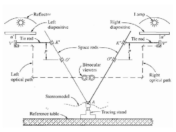
Stereoscopic Plotters • Stereoscopic plotters are instruments used to measure ground coordinates of points in the overlapped area by measuring their photo coordinates in stereo mode. • Two overlapping photos are used, either placed in projectors as the case in early models, or displayed in digital format as current technology. • Such plotters allow for the removal of the Y parallax, the effect of different of scale between the photos, tilt of photos,
Stereo plotters may be classified into three categories: 1 - Analogue Optical
• Film or transparent photos are positioned on the projectors, light is projected through them, their relative positions are adjusted to form a model to scale. • Points are measured as they are traced on the tracing table (4) in the graph above, a pencil at (11) will draw a map as the tracing table is moved. • Such a device is used to illustrate the idea, but not for production today.
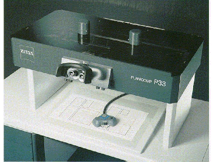
2 - Analytical Plotters • Still uses photographs, but the model is mathematical, • Two comparators are used to precisely measure photo coordinates, which are recorded digitally. • The stereo-model is seen through optics as a computer adjusts the photos for stereo viewing and measurements as the mouse is moved by driving servo motors. • A point is digitized by clicking a mouse when the floating mark rests on it to store the coordinates. • The digital output is stored and a CAD system can be used to produce a map, on he fly if needed
Zeiss P 3 analytical plotter
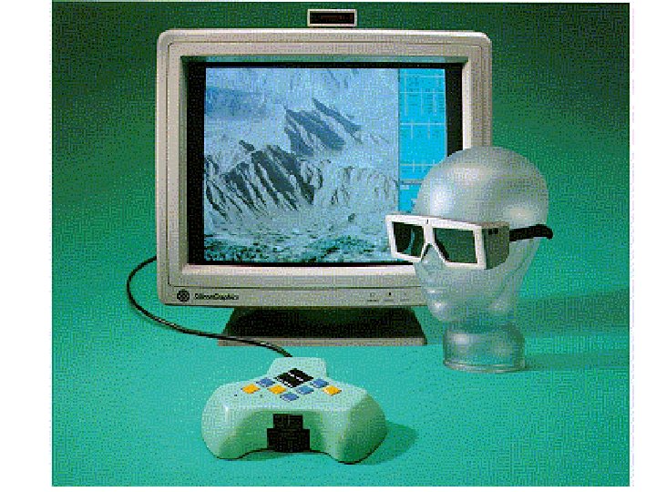
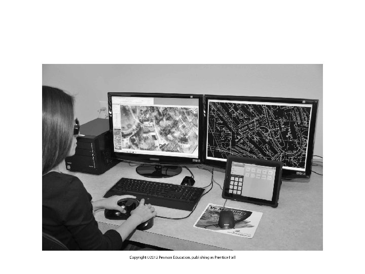
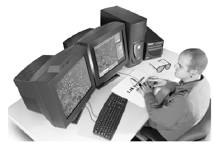
3 - Softcopy Photogrammetric Workstations • Softcopy workstations employ digital images, a software, a stereovision system, installed on a powerful computer. • The output is totally digital, and many operations are automated. • Softcopy is the current technology used for photogrammetric measurements. • Images are captured by a digital camera, or scanning photographs.
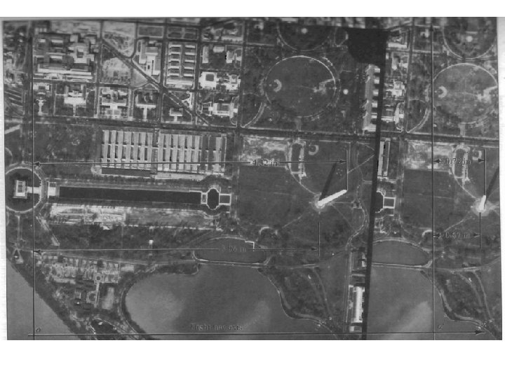
Ortho-photos • Orthographic projection of photographs. • Uniform scale, no relief displacement. • Serve as maps, what is difference between a map and a photograph. • now mainly through “digital image processing”. • If tilt displacement is also removed, you get “ ortho -rectified image” • Advantage of orthophoto maps
Orthophoto of Washington, DC