Stereo Vision By Suzan Kassabry Dima Saleh Lecturer

Stereo Vision By: Suzan Kassabry & Dima Saleh Lecturer: Prof. Hagit Hel. Or

Outline Interview stereo vision of humans Computer stereo vision The principle of triangulation Corresponding points problem • Special case: parallel camera’s Ø Disparity • Disparity map & depth from disparity Ø Basic stereo matching algorithm • SSD & NC • Image rectification Ø Other methods of obtaining depth • Stereo cameras • Structured light • Time of flight Ø Ø Ø

Interview Stereovision is a big field deals with 3 D information. Mainly it is separates it in two perspective: v. Human’s stereo vision v. Computer stereo vision In this lecture we are going to focus on the computer stereovision.

Human’s Stereovision is the ability to derive information about how far away objects are, based solely on the relative positions of the object in the two eyes. Two Eyes' Views Used and Fused in the Brain

Examples of general actions that depend heavily on stereo vision: o o o o Throwing, catching or hitting a ball Driving and parking a car Planning and building a three-dimensional object Threading a needle and sewing Reaching out to shake someone's hand Pouring into a container Stepping off a curb or step

Computer Stereo vision • Computer stereo vision is the extraction of 3 D information from digital images of the same scene. • The 3 D information extraction is a geometric approach and its called Triangulation

The principle of triangulation Triangulation is the problem of determining a point’s 3 D position from a set of corresponding image locations and known camera positions. How ? ? x 1 Left camera x 2 Right camera

The principle of triangulation Triangulation is the problem of determining a point’s 3 D position from a set of corresponding image locations and known camera positions. find the intersection of the rays in space corresponding to the points. x 1 Left camera The solution x 2 Right camera

The principle of triangulation Triangulation is the problem of determining a point’s 3 D position from a set of corresponding image locations and known camera positions. BUT!! This happens only in ideal world x 1 Left camera The solution x 2 Right camera

The principle of triangulation 3 D point § In the real world, the coordinates of image points cannot be measured with arbitrary accuracy. § Various types of noise, such as geometric noise from lens distortion or interest point detection error, lead to inaccuracies in the measured image coordinates. § The lines generated by the corresponding image points do not necessarily intersect in 3 D space. The rays do not intersect at the real 3 D point Left measured image point § Solution: find a 3 D point which optimally fits the measured image points. Right measured image point

The principle of triangulation

The corresponding points problem Corresponding points: the projection of 3 D point in different images taken by different positioned cameras. The corresponding points problem: finding pair of points one in each image that originated from the same point in 3 D.

The corresponding points problem ? ?

Epipolar geometry Image plane

Epipolar geometry Baseline Image plane Baseline : a line joining the camera centers

Epipolar geometry Baseline Image plane Epipoles : point of intersection of baseline with the image plane.

Epipolar geometry Epipolar plane Baseline Image plane Epipole Epipolar plane : plane containing baseline and world point

Epipolar geometry Epipolar line Epipolar plane Baseline Image plane Epipole Epipolar line: intersection of epipolar plane with the image plane

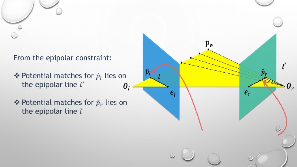
Epipolar constraint: Baseline Image plane

Epipolar constraint: Baseline Image plane

Epipolar constraint: Baseline Image plane

Epipolar constraint: Baseline Image plane

Epipolar constraint: Baseline Image plane

Epipolar constraint: Baseline Image plane

Epipolar constraint: Baseline Image plane

How do we find the epipolar lines ? !

How do we find the epipolar lines ? ! By the Fundamental matrix

Given a point in one image multiplying by the essential matrix will tell us the epipolar line in the second image. The Essential Matrix is a 3× 3 matrix that encodes epipolar geometry

Epipolar line: in vector form

Where does the essential matrix come from? !

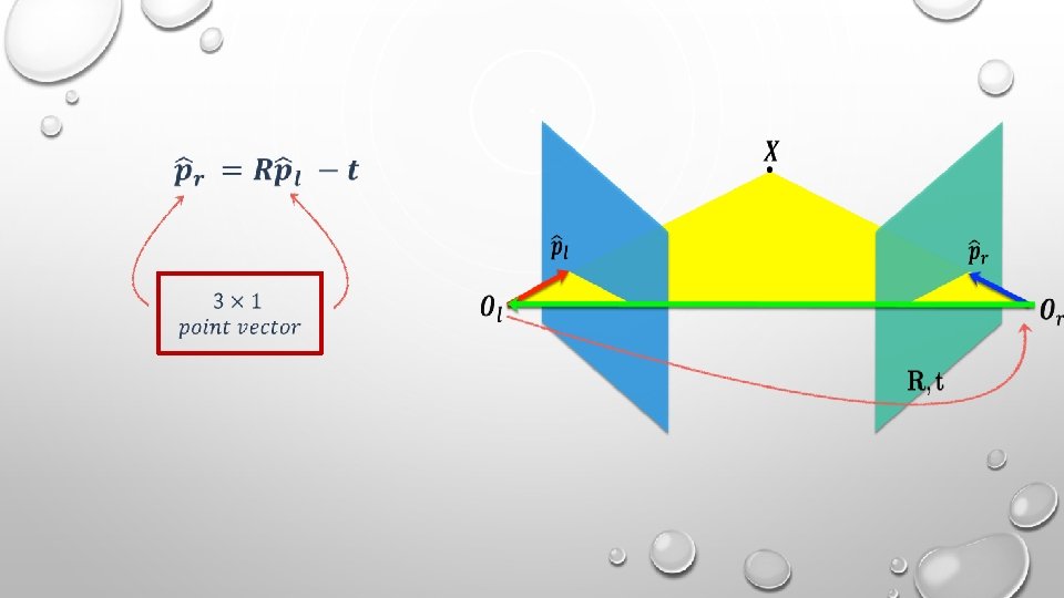
q If we assume that the camera’s are calibrated, then the points of the two images are normalized coordinates, that is, each is given with respect to it’s camera’s coordinate frame.

q If we assume that the camera’s are calibrated, then the points of the two images are normalized coordinates, that is, each is given with respect to it’s camera’s coordinate frame. q Assume we know, how to rotate and translate camera reference frame 1 to get to camera reference frame 2.
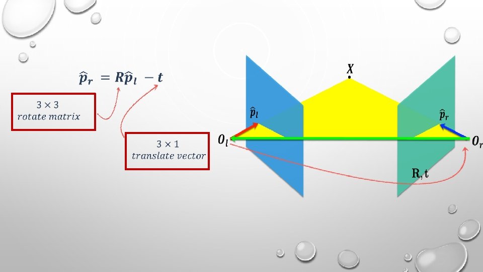

Reminder of cross-product Vector cross product takes two vectors and returns a third vector that’s perpendicular to both inputs. Matrix form: Skewsymmetric matrix

From algebra to geometry: We said that : Cross-product

Essential matrix We said that : Skew-symmetric matrix Let : Then : Essential matrix 3× 3

image coordinates camera coordinates

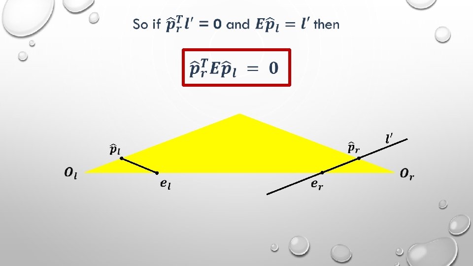
The fundamental matrix: We said that : This yields the following equation:

The fundamental matrix: We said that : This yields the following equation: Fundamenta l Matrix

The fundamental matrix: Intrinsic matrix Extrinsic matrix The fundamental matrix maps pixels to epipolar lines For all points that lie on the epipolar line : Then : 3× 3 matrix

How do we find the fundamental matrix when we don’t know K, R and t? !

The fundamental matrix: We can compute F from a few correspondences. Each pair correspondence points gives one linear equation in entries of F. So 8 pairs points enough to solve for F.

The fundamental matrix: By solving the linear equations, we find the 8 elements of the fundamental matrix

Parallel cameras are a special case of corresponding points problem Let's talk about it !

Special case: parallel cameras baseline T

Special case: parallel cameras

Special case: parallel cameras Why? !

Special case: parallel cameras

Special case: parallel cameras

Special case: parallel cameras

Essential matrix with parallel cameras: Assume we know the distance between the optical camera centers. Then : We know that : t

Essential matrix with parallel cameras: Assume we know the distance between the optical camera centers. Then : We know that : y coordinate is always the same t

Fundamental matrix with parallel cameras: Camera matrices :

Fundamental matrix with parallel cameras: Camera matrices :

Fundamental matrix with parallel cameras: Camera matrices :

Disparity is the distance between two points in the left and right image of a stereo pair.

Disparity is the distance between two points in the left and right image of a stereo pair. So, what relation there is between the disparity and the depth of a 3 D point? !

Disparity is the distance between two points in the left and right image of a stereo pair.

Disparity The camera situation from upside look, where Z is the depth of the 3 D point:

Disparity Similar triangles: From similarity: disparity

Disparity Similar triangles: From similarity: disparity depth is inversely proportional to disparity

Disparity map: Disparity map refers to the apparent pixel difference between a pair of stereo image.

Disparity map: q The disparity map as build according to one image of two stereo pair. q Each image gives a different disparity map Left image Disparity map according to left picture Right image

Disparity map: q The disparity map as build according to one image of two stereo pair. q Each image gives a different disparity map Left image Disparity map according to left picture Right image -2

Disparity map: q The disparity map as build according to one image of two stereo pair. q Each image gives a different disparity map Left image Disparity map according to left picture Right image -2 -2

Disparity map: q The disparity map as build according to one image of two stereo pair. q Each image gives a different disparity map Left image Disparity map according to left picture Right image -2 -2 -2

Disparity map: q The disparity map as build according to one image of two stereo pair. q Each image gives a different disparity map Left image Disparity map according to left picture Right image -2 -2 0 0

Disparity map: q The disparity map as build according to one image of two stereo pair. q Each image gives a different disparity map Left image Right image -2 -2 0 0 0 0 -2 -2 Disparity map according to left picture to right picture

Disparity map: Example: Left image Disparity map Right image
 Disparity map d(x, y) (x´, y´)=(x+D(x, y) Image")
Depth from disparity: Image i(x, y) Disparity map d(x, y) (x´, y´)=(x+D(x, y) Image i´(x´, y´)
 Disparity map d(x, y) (x´, y´)=(x+D(x, y) So")
Depth from disparity: Image i(x, y) Disparity map d(x, y) (x´, y´)=(x+D(x, y) So if we could find the corresponding points in two images, we could estimate relative depth… Image i´(x´, y´)

Basic stereo matching algorithm For each pixel in the first image -Find corresponding epipolar line in the right image -Examine all pixels on the epipolar line -Select the best match -Triangulate the matches to get depth information

Basic stereo matching algorithm For each pixel in the first image -Find corresponding epipolar line in the right image -Examine all pixels on the epipolar line -Select the best match -Triangulate the matches to get depth information

Basic stereo matching algorithm For each pixel in the first image -Find corresponding epipolar line in the right image -Examine all pixels on the epipolar line -Select the best match -Triangulate the matches to get depth information

Basic stereo matching algorithm For each pixel in the first image -Find corresponding epipolar line in the right image -Examine all pixels on the epipolar line -Select the best match -Triangulate the matches to get depth information

Basic stereo matching algorithm For each pixel in the first image -Find corresponding epipolar line in the right image -Examine all pixels on the epipolar line -Select the best match -Triangulate the matches to get depth information

Basic stereo matching algorithm For each pixel in the first image -Find corresponding epipolar line in the right image -Examine all pixels on the epipolar line -Select the best match -Triangulate the matches to get depth information Question: how do we determine the best match?

Basic stereo matching algorithm Question: how do we determine the best match? Two methods: q. Sum of squared differences SSD q. Normalized correlation NC
 : § Search for")
Basic stereo matching algorithm q. Sum of squared differences (SSD) : § Search for the patch with the minimal SSD
 : § Search for the patch")
Basic stereo matching algorithm q. Normalized correlation (NC) : § Search for the patch with the maximal NC

Image rectification So how can make the epipolar lines horizontal ?

Image rectification So how can make the epipolar lines horizontal ? Image rectification

Image rectification is a transformation process used to project images onto a common image plane, that parallel to the line between camera centers (Baseline). How do we do this?

Image rectification is a transformation process used to project images onto a common image plane, that parallel to the line between camera centers (Baseline). Need two homographies matrix (3 x 3 transform), one for each input image reprojection

Image rectification q Goal : Simplify stereo matching by ‘warping’ the images. q Apply projective transformation so that epipolar lines correspond to horizontal scanlines

Image rectification q Goal : Simplify stereo matching by ‘warping’ the images. q Apply projective transformation so that epipolar lines correspond to horizontal scanlines q The homography matrix should minimize image distortion.

Image rectification 1. We assume the world origin is at the first camera.

Image rectification

Image rectification

Image rectification

Image rectification

Image rectification

Basic stereo matching algorithm • If necessary, rectify the two stereo images to transform epipolar lines into scanlines - For each pixel x in the first image - Find corresponding epipolar scanline in the right image - Examine all pixels on the scanline and pick the best match x’ - Compute disparity x–x’ and set depth(x) = T*f/(x–x’)
 q Stereo camera q Structured light")
Other methods of obtaining 3 D information (depth) q Stereo camera q Structured light q Time of flight
 Stereo camera: A stereo camera is")
Other methods of obtaining 3 D information (depth) Stereo camera: A stereo camera is a type of camera with two or more lenses with a separate image sensor or film frame for each lens. This allows the camera to simulate human binocular vision, and therefore gives it the ability to capture three-dimensional images.
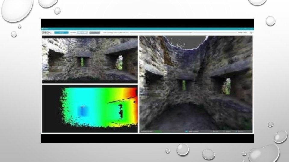
 Stereo camera: Tara camera Zed camera")
Other methods of obtaining 3 D information (depth) Stereo camera: Tara camera Zed camera
 Structured light: A structured light scanning")
Other methods of obtaining 3 D information (depth) Structured light: A structured light scanning system projects different light patterns, or structures, and captures the light as it falls onto the scene. It then uses the information about how the patterns appear after being distorted by the scene to eventually recover the 3 D geometry. Mainly there is two types: § Line scan-based cameras § Point scan-based cameras
 Structured light:")
Other methods of obtaining 3 D information (depth) Structured light:
 Example camera: Kinect version 1")
Other methods of obtaining 3 D information (depth) Example camera: Kinect version 1
 Example camera: Kinect version 1")
Other methods of obtaining 3 D information (depth) Example camera: Kinect version 1
 Time of flight camera: A Time")
Other methods of obtaining 3 D information (depth) Time of flight camera: A Time of Flight camera determines depth information by measuring the round-trip time of an artificial light signal provided by a laser or an LED.
 Example camera: Kinect version 2")
Other methods of obtaining 3 D information (depth) Example camera: Kinect version 2

Summary Stereo is one of the most important field in computer vision. It deals with methods of extracting a 3 D information. This field is very wide and interesting, and we have talked about the basic principles in it. Mainly, we have showed you how to get object’s distance from two image pictures, that have been taken from similar cameras in a different positions. Ofcourse there is another ways to get 3 D information of a scene, as we have showed you at the end.

v Referenses: • https: //www. vision 3 d. com/stereo. html • https: //www. nature. com/articles/eye 2014279#: ~: text=Binocular%20 stereopsis%2 C%20 or%2 0 stereo%20 vision, both%20 sensory%20 and%20 motor%20 abilities. • https: //en. wikipedia. org/wiki/Computer_stereo_vision#: ~: text=Computer%20 stereo%20 visi on%20 is%20 the, objects%20 in%20 the%20 two%20 panels. • https: //www. e-consystems. com/blog/camera/what-is-a-stereo-vision-camera/ • http: //szeliski. org/Book/drafts/Szeliski. Book_20100903_draft. pdf • https: //users. cecs. anu. edu. au/~hartley/Papers/triangulation. pdf • https: //en. wikipedia. org/wiki/Triangulation_(computer_vision) • https: //en. wikipedia. org/wiki/Stereo_camera • https: //onlinelibrary. wiley. com/doi/full/10. 1002/047134608 X. W 8298

v Referenses: • http: //vision. stanford. edu/teaching/cs 131_fall 1415/lectures/lecture 9_10_stereo_cs 131. pdf • https: //www. pocket-lint. com/phones/news/147024 -what-is-a-time-of-flight-camera-and-whichphones-have-it • https: //en. wikipedia. org/wiki/Time-offlight_camera#: ~: text=A%20 time%2 Dof%2 Dflight%20 camera, a%20 laser%20 or%20 an%20 LED. • http: //www. cs. cmu. edu/~16385/ • http: //www. close-range. com/docs/Image_rectification. pdf • http: //engineering. nyu. edu/~gerig/CS-GY-6643 -S 2016/CS-GY_6643_Computer_Vision. html • https: //www. cs. utoronto. ca/~fidler/teaching/2019/CSC 420. html#: ~: text=This%20 class%20 is%20 an%20 i ntroduction, make%20 the%20 computers%20%22 see%22. &text=The%20 goal%20 of%20 the%20 class, them%20 for%20 real%2 Dworld%20 applications. • http: //vision. stanford. edu/teaching/cs 131_fall 1415/lectures/lecture 9_10_stereo_cs 131. pdf

Thank you
- Slides: 112