
Stepping motors Jari Kostamo Outline Introduction Stepping motor
- Slides: 22
Stepping motors Jari Kostamo
Outline • • Introduction Stepping motor structures Properties of stepping motor Control of stepping motors
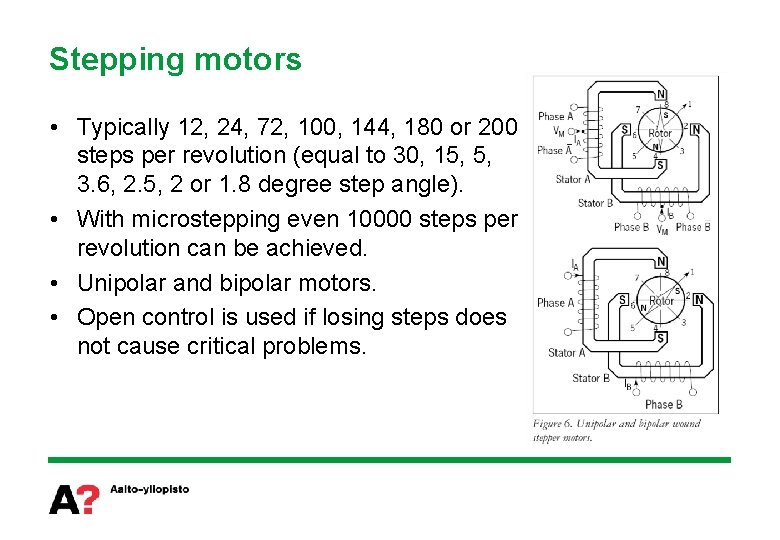
Stepping motor • Stepping motor is an electromechanical device which converts electrical pulses to discrete mechanical translation. • Axle of the stepping motor turns in discrete steps when the coils are pulsed with electric current in proper sequence • Direction of rotation depends on the sequence of the pulses • Angle of rotation is determined by the number of pulses • Rotation speed is determined by the frequency of the pulses
Stepping motor • • • Typically for small power applications (holding torque in a range of 1 – 1000 Ncm or power less than 750 W) Low cost Easy to interface with digital control with microcontrollers. Precise control without feedback (step angle as low as 0, 5 o) Can be used with feedback Stepping rated possible up to 40 k. Hz (drive) or 3 k. Hz (pull in freq) Dynamical properties are only moderate due to the operating principle Can lose steps when loaded heavily Operating range may contain problematic areas Achieved position is not perfectly precise but the motor can be displaced with a small torque. Operating is slightly shaking Audible noise due to the stepping
Stepping motors • Typically 12, 24, 72, 100, 144, 180 or 200 steps per revolution (equal to 30, 15, 5, 3. 6, 2. 5, 2 or 1. 8 degree step angle). • With microstepping even 10000 steps per revolution can be achieved. • Unipolar and bipolar motors. • Open control is used if losing steps does not cause critical problems.
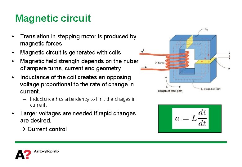
Magnetic circuit • Translation in stepping motor is produced by magnetic forces • • Magnetic circuit is generated with coils • Inductance of the coil creates an opposing voltage proportional to the rate of change in current. Magnetic field strength depends on the nuber of ampere turns, current and geometry – Inductance has a tendency to limit the chages in current. • Larger voltages are needed if rapid changes are desired. Current control
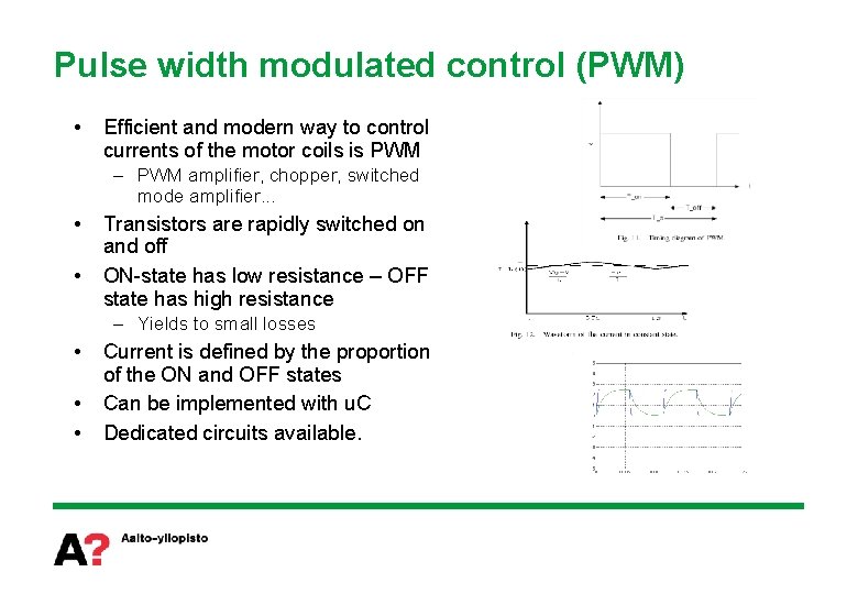
Pulse width modulated control (PWM) • Efficient and modern way to control currents of the motor coils is PWM – PWM amplifier, chopper, switched mode amplifier. . . • • Transistors are rapidly switched on and off ON-state has low resistance – OFF state has high resistance – Yields to small losses • • • Current is defined by the proportion of the ON and OFF states Can be implemented with u. C Dedicated circuits available.
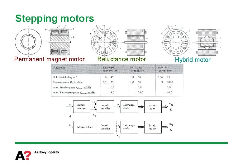
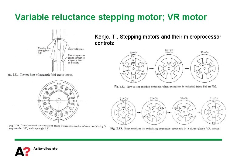
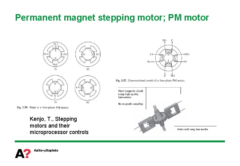
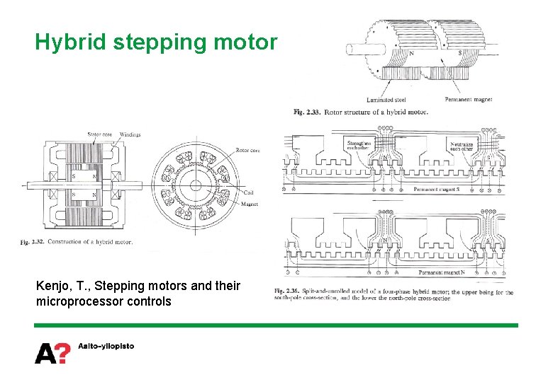
Stepping motors Permanent magnet motor Reluctance motor Hybrid motor
Variable reluctance stepping motor; VR motor Kenjo, T. , Stepping motors and their microprocessor controls
Permanent magnet stepping motor; PM motor Kenjo, T. , Stepping motors and their microprocessor controls
Hybrid stepping motor Kenjo, T. , Stepping motors and their microprocessor controls
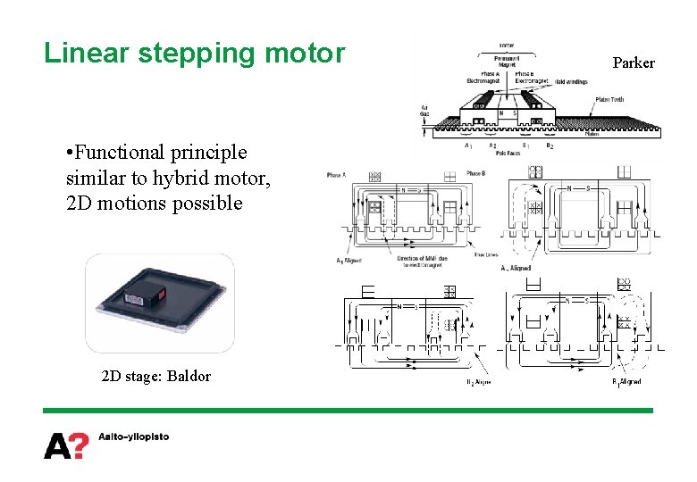
Linear stepping motor • Functional principle similar to hybrid motor, 2 D motions possible 2 D stage: Baldor Parker
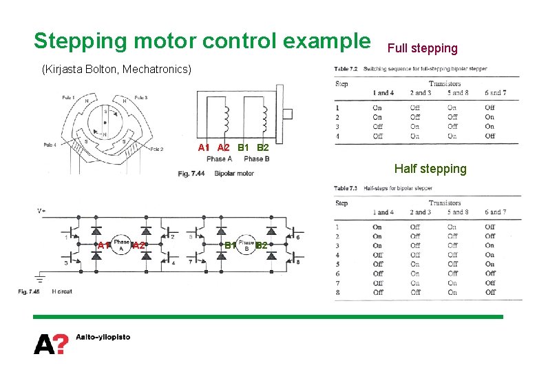
Stepping motor control example Full stepping (Kirjasta Bolton, Mechatronics) A 1 A 2 B 1 B 2 Half stepping A 1 A 2 B 1 B 2
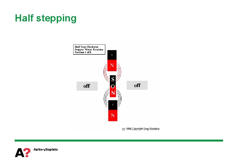
Half stepping
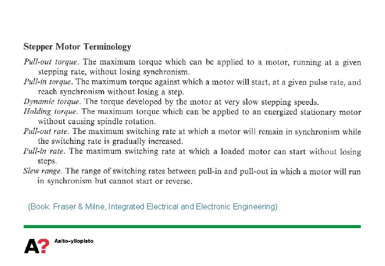
(Book: Fraser & Milne, Integrated Electrical and Electronic Engineering)
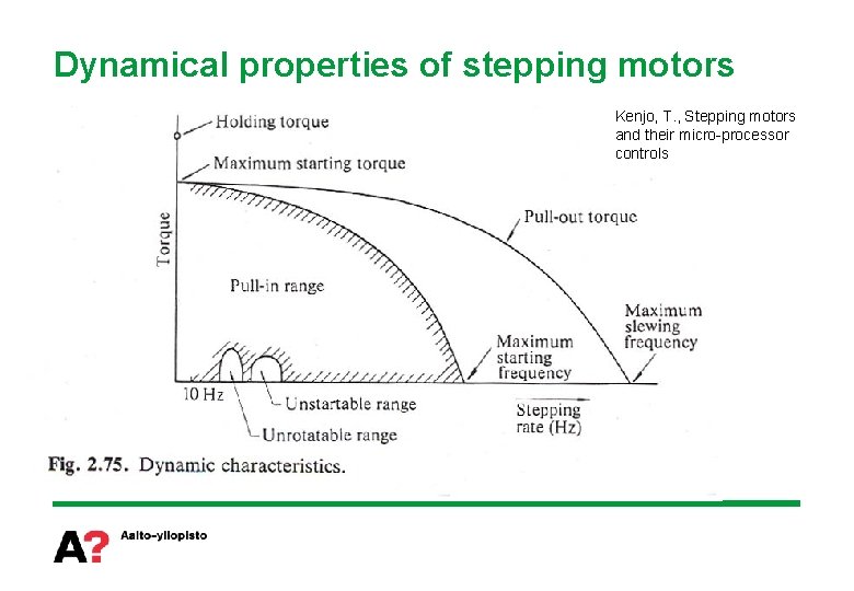
Dynamical properties of stepping motors Kenjo, T. , Stepping motors and their micro-processor controls
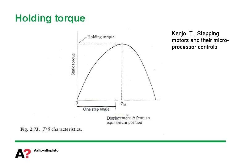
Holding torque Kenjo, T. , Stepping motors and their microprocessor controls
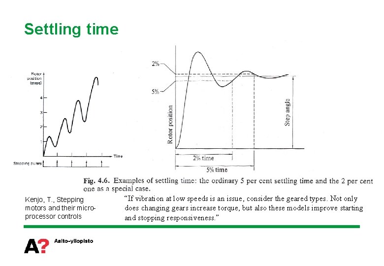
Settling time Kenjo, T. , Stepping motors and their microprocessor controls “If vibration at low speeds is an issue, consider the geared types. Not only does changing gears increase torque, but also these models improve starting and stopping responsiveness. ”
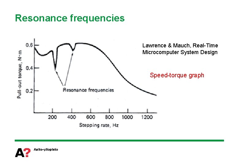
Resonance frequencies Lawrence & Mauch, Real-Time Microcomputer System Design Speed-torque graph
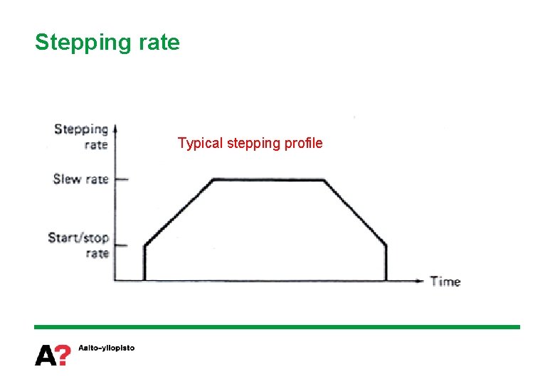
Stepping rate Typical stepping profile
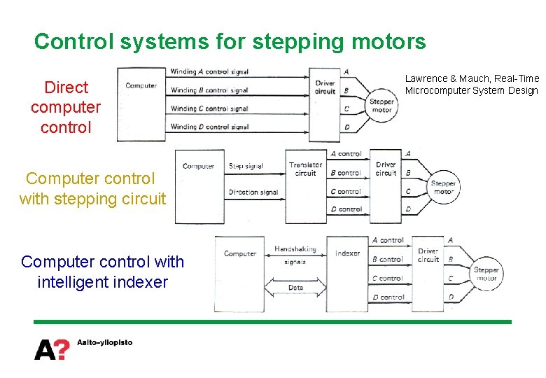
Control systems for stepping motors Direct computer control Computer control with stepping circuit Computer control with intelligent indexer Lawrence & Mauch, Real-Time Microcomputer System Design
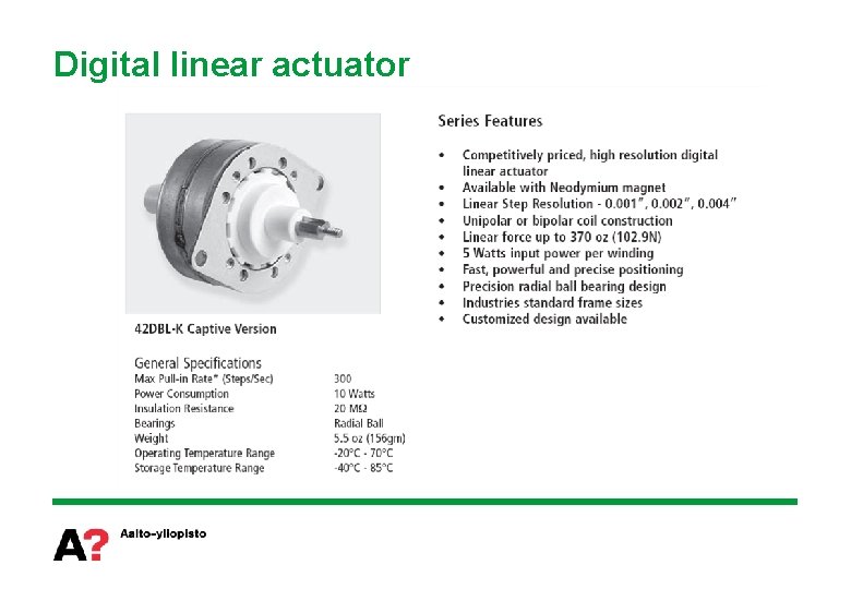
Digital linear actuator