Steering Systems Basics Steering Systems Manual steering system

Steering Systems Basics

Steering Systems • Manual steering system – relies solely on the driver to provide steering force • Power assist – (power steering) – uses hydraulic or electric power to help the driver apply steering force

Steering Systems • Both manual and power steering systems have common components. • Input components: • Steering wheel • Steering column • Steering shaft

Steering Column and Wheel

Steering Shaft

Steering Shaft to Gear • The steering shaft connects to the steering gear through one or more: • Universal joints • Flexible steering coupler

Steering Systems • The steering gear changes the rotary motion of the wheel into linear motion of the steering linkage.

Steering Gear


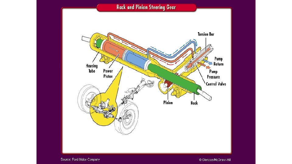
Rack and Pinion Steering Gear

Steering Linkage • Connects the linear motion of the steering gear to the steering arms. • Parallelogram type linkage (typical) – • • • Pitman arm Idler arm Center link Inner tie rod Outer tie rod Tie rod adjustment sleeve

Parallelogram Type Linkage

Parallelogram Type Linkage

Parallelogram Type Linkage • “Parallelogram” refers to the shape that the linkage makes on a turn.

Parallelogram Type Linkage Idler Arm Pitman Arm

Steering Linkage • Rack and Pinion linkage • Inner tie rod • Outer tie rod

Ball Sockets • Allow suspension travel without binding • Tie rods – located at the steering knuckle. • Also at the center link on parallelogram type. • Ball joints – located at the top and bottom of the knuckle. Allows for movement between the knuckle and control arm(s).

Steering Knuckle

Tie Rod

Ball Joints

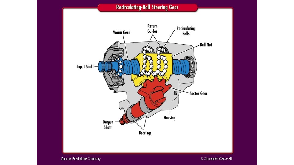
Recirculating-Ball Steering Gear • Primarily used on trucks, vans and larger vehicles. • Also used on most passenger vehicles prior to 1980. • Used in conjunction with a parallelogram-type linkage system.

Recirculating-Ball Steering Gear • Uses a series of recirculating balls on a worm shaft to transfer steering-wheel movement to tire and wheel movement.

Recirculating-Ball Steering Gear

Recirculating-Ball Steering Gear • The steel balls within the gear box housing constantly recirculate within the guide paths. • They move from one end of the ball nut through return guides to reenter the ball nut at the opposite end. • The balls provide low-friction contact points between the worm gear and the internal grooves of the ball nut.

Recirculating-Ball Steering Gear
 of the recirculatingball steering box")
Recirculating-Ball Steering Gear • The sector shaft (output shaft) of the recirculatingball steering box uses a pitman arm for an output device.

Recirculating-Ball Steering Gear • The pitman arm connects to a center link (also called a drag link)

Recirculating-Ball Steering Gear • The other end of the center link is attached to a idler arm

Recirculating-Ball Steering Gear • The pitman arm and idler arm act as the center links pivot points.

Rack and Pinion Systems • Most passenger vehicles today use rack and pinion steering systems. • Generally contained in one complete housing. • The steering shaft connects to a pinion shaft through a universal joint or coupler. • The pinion gear meshes with a a rack of gear teeth.

Rack and Pinion Systems

Rack and Pinion Systems • Fewer parts • Lighter • Modular • Saves space • Generally not as strong as a recirculating-ball type system • Suitable for today’s lighter cars.

Center-Link Type Rack and Pinion • Used when the rack is mounted on the firewall

Steering Systems Basics • Why are some vehicles still equipped with parallelogram type steering systems? • Why do most vehicles use a rack and pinion design? • Why is a parallelogram system called a parallelogram system?
- Slides: 36