STec 55 X Autopilot Cirrus Transition Course Revision


- Slides: 40

S-Tec 55 X Autopilot Cirrus Transition Course Revision 08/06/2006

The system information, procedures and guidelines found in this presentation are for Reference Only. The information & procedures in this presentation have been taken from the FAA Approved Airplane Flight Manual and Pilot’s Operating Handbook (POH). The Information & Procedures in this presentation DO NOT SUPERSEDE the Information & Procedures in the POH. In the event of conflict, the POH shall take precedence.

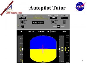
General Rate autopilot Two axis control system Roll axis controlled by aileron trim motor and spring cartridge Pitch axis controlled by pitch trim motor Powered by Essential Bus

System Components


Manufacturers Notes SR-22 installation utilizes aircrafts roll trim actuator. The automatic trim feature is not utilized.

Limitations Operation prohibited at speeds in excess of 185 KIAS Autopilot must be disengaged for takeoff and landing Autopilot must be disengaged for the missed approach, go around, or balked landing Flaps must be set to 50% for autopilot operation in Altitude Hold at speeds below 95 KIAS Flap deflection is limited to 50% during autopilot operations The S-Tec System 55 X POH must be carried in the airplane and available to the pilot while in flight

Limitations Autopilot must be disconnected in moderate or severe turbulence Minimum engagement height is 400 feet AGL For VOR/GPS, ILS glideslope and localizer intercept, capture, and tracking, the following limitations apply: Autopilot must be disengaged no later than 100 feet below the MDA Autopilot must be disconnected if course deviation exceeds 50% (approach may be continued if hand flown) Autopilot must be disengaged at the Decision Height 12 knot maximum crosswind component between the outer marker and the missed approach point If the crosswind component is greater than 12 knots but less than 17, the intercept should occur at least 10 miles outside the outer marker

Limitations The intercept of the localizer shall occur at least 5 miles outside of the outer marker The intercept angle shall be no greater than 45° The glideslope is approached in such a manner to allow automatic arming of the glideslope, or if the glideslope is manually armed no more than 15% above the glideslope

Initialization At power up verify illumination of all autopilot mode annunciators CWS and TRIM annunciators will not illuminate RDY will illuminate when Turn Coordinator gyro has reached an operational speed

Preflight Test Heading Mode Center HDG Bug on PFD Select HDG Mode on autopilot mode controller Rotate HDG knob left and right of lubber line Verify proper roll control inputs Vertical Speed Select VS mode on autopilot mode controller Rotate VS control knob to + 500 feet and – 500 feet Verify proper pitch control inputs

Preflight Test Altitude Hold Select ALT mode on autopilot mode controller Verify ALT annunciation, VS annunciation extinguishes, and stationary yoke Overpower Grasp control yoke and move in all directions. Action should be smooth in all directions with no noise or jerky feel

Preflight Test Radio Check Tune to a valid NAV station Select VLOC on HSI display Select NAV mode on autopilot mode controller Turn CDI left and right of course verifying roll inputs in direction of needle adjustment

Autopilot Disconnect Check Select HDG and ALT mode Press A/P DISC switch, verify disconnect Engage pitch trim, verify disconnect Holding DISC switch will cancel beeping

In-Flight Procedures Heading Mode Select HDG Mode on autopilot mode controller Position HDG Bug as desired NOTE Same as Pre Flight test procedures Be aware that if the HDG Bug exceeds 180° from the current heading, the AP will want to turn in the opposite direction as desired

In-Flight Procedures Navigation Mode Ensure a reliable VOR or Localizer signal exists Select the desired course using the CDI Select NAV mode on the autopilot mode controller NOTE If the CDI is at full scale deflection the autopilot will command a default 45° intercept angle To intercept the course at an angle other than 45° Position the HDG Bug to the desired intercept angle Hold the HDG button while selecting NAV mode on autopilot mode controller Autopilot will fly selected heading until course intercept

In-Flight Procedures GPS Steering Mode Ensure a reliable GPS signal and flight plan exist Verify the HSI will auto-slew your course Press the NAV button twice on the autopilot mode controller Verify illumination of NAV and GPSS annunciators

In-Flight Procedures GPS Steering Mode If the CDI is at full scale deflection the autopilot will command a default 45° intercept angle To intercept the course at an NOTE angle other than 45° Position the HDG Bug to the desired intercept angle Hold the HDG button while pressing the NAV button twice on autopilot mode controller Autopilot will fly selected heading until course intercept

In-Flight Procedures Difference between NAV mode and GPSS mode While the AP is in NAV mode it will determine what guidance corrections are needed by reference to what is happening on the HSI. While the AP is in GPSS mode it will determine what guidance corrections are needed by reference to what is happening on the GPS unit. (Selected GPS unit if using PFD) NOTE The AP flies a much more accurate course because the difference between your desired course (DTK) and your current track (TRK) can be determined by the GPS unit. GPSS also allows turn anticipation. A HSI does not know your groundspeed, distance to waypoint or degree of course change to determine an early turn, the GPS does.

In-Flight Procedures Altitude Hold Mode Manually fly the airplane to the desired altitude and level off NOTE A roll mode (HDG/NAV/GPSS/APR) must be selected prior to engaging a pitch mode Select ALT mode on autopilot mode controller Altitude may be fine tuned using the VS knob 20 foot increments Maximum authority +/- 360 feet

In-Flight Procedures Vertical Speed Mode Select VS mode on autopilot mode controller NOTE A roll mode (HDG/NAV/GPSS/APR) must be selected prior to engaging a pitch mode NOTE Select the desired vertical speed using the VS knob on the PFD 100 foot increments Maximum authority +/1600 feet

In-Flight Procedures Altitude Capture The autopilot will capture an altitude that is selected in the PFD Select the desired altitude on the PFD Select the desired climb/descent rate If none is selected a +/- 500 fpm is defaulted Engage a roll mode (HDG/NAV/GPSS/APR) Hold the VS button while pressing the ALT button and verify that both annunciators remain lit

In-Flight Procedures Vertical Speed Mode CAUTION A flashing VS annunciator indicates excessive error between selected vertical speed and actual vertical speed. The pilot should adjust power or vertical speed rate selected to correct error Be aware that the AP will stall the aircraft in the event that a vertical speed is to high for the current altitude or power setting

Approach Procedures VOR / Localizer Approach Ensure a reliable VOR or Localizer signal exists Select the desired course using the CDI Select APR mode on the autopilot mode controller Verify illumination of NAV and APR annunciators NOTE Course intercept is identical to the In-Flight Procedures For station passage, select HDG mode with the HDG bug set within 5° of the selected course Procedure turns must be flown using HDG mode

Approach Procedures Localizer Back Course Approach Ensure a reliable Localizer signal exists Select the desired course using the CDI Select APR and REV modes on the autopilot mode controller Verify illumination of NAV, APR, and REV annunciators NOTE Course intercept is identical to the In-Flight Procedures The front course should always be selected course when executing a LOC BC approach Procedure turns must be flown using HDG mode

Approach Procedures GPS Approach Ensure the GPS approach has been properly loaded and activated Verify the HSI will auto-slew your inbound course Select GPSS mode on the autopilot mode controller NOTE Course intercept is identical to the In-Flight Procedures

Approach Procedures GPS Approach NOTE Procedure turns must be flown using HDG mode. The autopilot will fly the outbound and the inbound segment of an approach. However you must fly the procedure turn using HDG mode Although displayed on the GPS, the autopilot is not capable of flying the depicted turn without pilot action

Approach Procedures ILS Approach Ensure a reliable Localizer signal exists Verify that the HSI will auto-slew your inbound course Select APR mode on the autopilot mode controller Verify illumination of NAV and APR annunciators NOTE Course intercept is identical to the In-Flight Procedures Procedure turns must be flown using HDG mode If it is necessary to track outbound on the front course, REV mode must be selected

Approach Procedures ILS Approach Glideslope Coupling APR and ALT modes must be selected Aircraft must be within ½ scale deflection of localizer Aircraft must be 60% or more below the glideslope Condition must exist for 10 seconds for GS mode to arm Arm indicated by illumination of ALT and GS annunciators ALT annunciator extinguishes at glideslope intercept NOTE GS mode may be manually engaged by pressing ALT once when in ALT mode and a glideslope signal exists as long as the aircraft has the criteria above

Abnormal Procedures WARNING Do not attempt to correct autopilot malfunctions unless you are in a safe maneuvering phase of flight and at a safe altitude

Abnormal Procedures Autopilot Disconnect Annunciation Flashing RDY for 5 seconds with audible tone Condition Autopilot disconnect. All annunciations except RDY are cleared. Action None.

Abnormal Procedures Low Gyro Speed Annunciation Flashing RDY with audible tone then goes out Condition Turn coordinator gyro speed low. Autopilot disengages and cannot be re-engaged. Action Check power to turn coordinator. If starting aircraft in cold weather, allow additional time for gyro to come to speed.

Abnormal Procedures Off Course Annunciation Flashing NAV, REV, or APR Condition Off navigation course by 50% needle deviation or more. Action Use HDG mode until problem is identified. Crosscheck raw NAV data, compass heading, and radio operation.

Abnormal Procedures Invalid radio navigation signal Annunciation Flashing NAV, REV, or APR with steady FAIL Condition Invalid radio navigation signal Action Check Nav radio for proper reception. Use HDG mode until problem is corrected.

Abnormal Procedures Excessive Vertical Speed Error Annunciation Flashing VS Condition Excessive vertical speed error over selected vertical speed. Usually occurs in climb. Action Reduce VS command and/or adjust power as appropriate.

Abnormal Procedures Glideslope deviation Annunciation Flashing GS Condition Off glideslope centerline by 50% needle deviation or more. Action Check altitude and power. Adjust power as appropriate.

Abnormal Procedures Invalid Glideslope signal Annunciation Flashing GS with steady FAIL Condition Invalid glideslope radio navigation signal. Action Disconnect autopilot and initiate go-around or missed approach procedure. Inform ATC.

Abnormal Procedures Manual Glideslope Disabled Annunciation Flashing GS plus ALT Condition Manual glideslope disabled. Action Re-enable by pressing NAV mode button.

Emergency Procedures Autopilot Malfunction The autopilot may be disconnected by: Pressing A/P DISC on the control yoke Using manual pitch trim with a vertical mode selected Pulling the Autopilot Circuit Breaker WARNING Due to the positioning on the circuit breaker panel, the pilot should be able to identify the following circuit breakers without visual reference Autopilot Pitch Trim Servo Roll Trim Servo

Emergency Procedures Recovery – Loss of Altitude Flight Phase Bank Angle Altitude Loss Climb 40° 200 feet Cruise 45° 300 feet Descent 40° 350 feet Maneuvering 10° 60 feet Approach 10° 80 feet WARNING Use of these figures assumes an immediate response to an autopilot malfunction
 Stec 30
 Stec 55 autopilot
 Scope and limitation significance of the study
 Stec 55
 Revision passive
 Autopilot to tableau
 Kap 140
 Kap 140 autopilot
 Autopilot
 Autopilot achtsamkeit
 Autopilot trading forex
 Nastel autopilot
 Cirrus link solutions
 Cumulus stratus and cirrus clouds
 Cirrus
 Cirrus stratus cumulus cumulonimbus clouds
 Nimbostratus clouds
 Prostytucja
 How does cumulus clouds form
 Benzydamina neurogroove
 How high is cloud level
 How do clouds form
 Cumulus stratus cirrus nimbus
 Cut brick lengthwise
 Course title and course number
 Course interne course externe
 How useful is this source
 E. writing connection
 Geometría capítulo 7 revisión respuestas
 Igcse english tips and tricks
 Gcse maths revision ppt
 Imedia exam questions
 Year 6 tips
 Lady macbeth
 Regular verbs affirmative form
 Making a revision timetable
 Revision module 1
 Revisión fundamental
 Virtue ethics revision
 Decimal revision
 Street works revision
