
Steady State Analysis for the Beam Loading Transient
Steady State Analysis for the Beam Loading Transient Stability in the Storage Ring RF System Haipeng Wang Robert Rimmer, Shaoheng Wang and Jiquan Guo Thomas Jefferson Lab, Newport News Virginia, USA
Abstract and Outline • The beam aborting, ion clearing gaps or uneven filling bunch train cause large beam phase transients in the RF cavity control systems such transient can cause luminosity loss for the colliders like EICs (JLEIC or e. RHIC) CEPC Spp. C. Severity of such transient can even cause the beam loss due to the Robinson instability • We have first analyzed the beam stability criteria in the steady state and estimated the transient effects in the Feedback RF controls with a given klystron overhead power • This analytical model combing with other instability criteria has been applied to the RF system design parameters for the JLEIC e-ring, CEPC • Robinson instability analysis for existing storage rings like BECP-II, PEP-II and ALS will be discussed • Beam transient compensation experiment result carried out at BEPC-II in December 6 -10, 2016. Transient Beam Loading 2
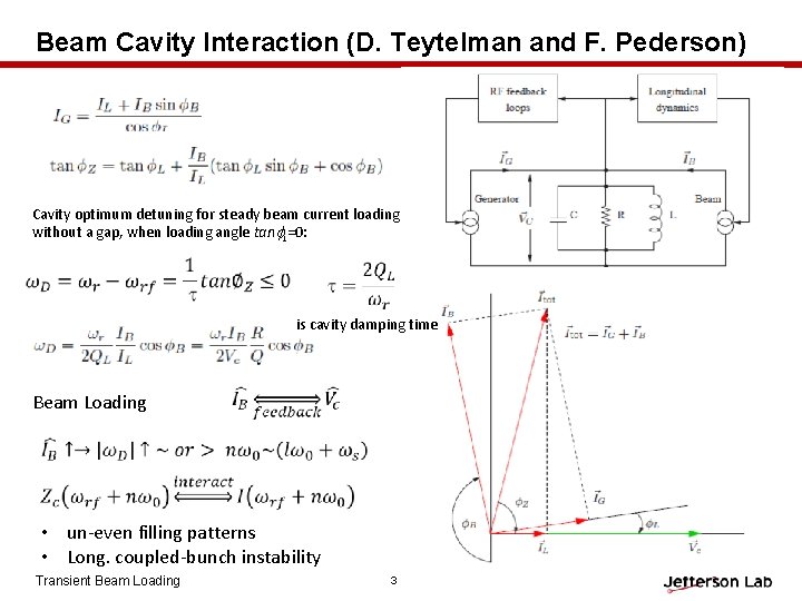
Beam Cavity Interaction (D. Teytelman and F. Pederson) Cavity optimum detuning for steady beam current loading without a gap, when loading angle tanf. L=0: is cavity damping time Beam Loading • un-even filling patterns • Long. coupled-bunch instability Transient Beam Loading 3

Beam Loading Transient (D. Teytelman and F. Pederson) Synchronous phase transients: Uneven filling patterns =>amplitude modulation IB=>beam signal has power at Zc( rf-n 0)=>Amp & pha. Modulation of Vc=> changes of long. s, , and B. Long gap for abort kicker rise time and ion clearing, beam current envelope amplitude and width Ib is the pre bunch current For D< 0 -2/ : Transient Beam Loading 4
![Beam Gap Transient Analysis in Steady State (Kerl Bane etc. [1]) Voltage difference induced](http://slidetodoc.com/presentation_image_h2/43c48326c4a6343d153ebed8c9d69988/image-5.jpg "Beam Gap Transient Analysis in Steady State (Kerl Bane etc. [1]) Voltage difference induced")
Beam Gap Transient Analysis in Steady State (Kerl Bane etc. [1]) Voltage difference induced across a bunch train: This formula can be used for either N>>1 or Ng>>1 for JLEIC for CEPC or Example of BEPC-II run N=357, Ng=39 Example of NLC damping ring N=90 Ng=43 Transient Beam Loading 5
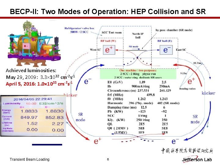
BECP-II: Two Modes of Operation: HEP Collision and SR Achieved luminosities: May 29, 2009: 3. 3× 1032 cm-2 s-1 April 5, 2016: 1. 0× 1033 cm-2 s-1 Transient Beam Loading 6
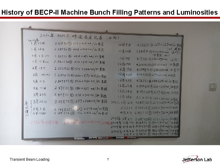
History of BECP-II Machine Bunch Filling Patterns and Luminosities Transient Beam Loading 7
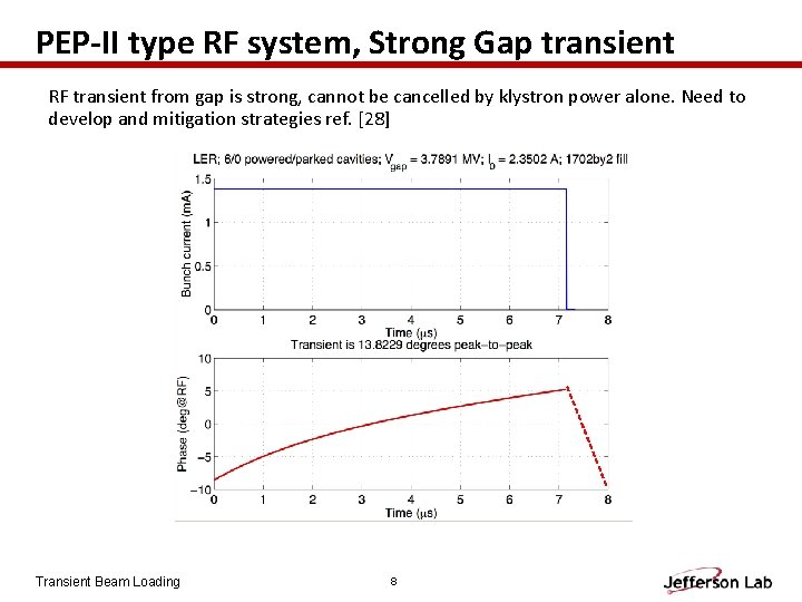
PEP-II type RF system, Strong Gap transient RF transient from gap is strong, cannot be cancelled by klystron power alone. Need to develop and mitigation strategies ref. [28] Transient Beam Loading 8
![Beam Transient Analysis in Steady State (H. Wang etc [25]) Data example of BEPC-II](http://slidetodoc.com/presentation_image_h2/43c48326c4a6343d153ebed8c9d69988/image-9.jpg "Beam Transient Analysis in Steady State (H. Wang etc [25]) Data example of BEPC-II")
Beam Transient Analysis in Steady State (H. Wang etc [25]) Data example of BEPC-II run at 1. 89 Ge. V on April 05, 2016 : Transient Beam Loading 9
![Beam Transient Analysis in Steady State (H. Wang etc [25]) Data example of BEPC-II](http://slidetodoc.com/presentation_image_h2/43c48326c4a6343d153ebed8c9d69988/image-10.jpg "Beam Transient Analysis in Steady State (H. Wang etc [25]) Data example of BEPC-II")
Beam Transient Analysis in Steady State (H. Wang etc [25]) Data example of BEPC-II run at 1. 89 Ge. V on April 05, 2016 : Transient Beam Loading 10
![Beam Transient Analysis in Steady State (H. Wang etc [25]) Data example of BEPC-II](http://slidetodoc.com/presentation_image_h2/43c48326c4a6343d153ebed8c9d69988/image-11.jpg "Beam Transient Analysis in Steady State (H. Wang etc [25]) Data example of BEPC-II")
Beam Transient Analysis in Steady State (H. Wang etc [25]) Data example of BEPC-II run at 1. 89 Ge. V on April 05, 2016 : • Could we open up the gap to see the loading angle transient? • Robinson stability or power limits? • Increase the DFB gain? 1. 65 o Transient Beam Loading 11

Beam Transient Beam Loading: from Concept, Proposal to Actual Experiment Proposal by R. Rimmer On 11/23/2016 J. Byrd , 2001 REF. [7] • • Experiment log pages White board discussion at IHEP for transient beam load experiment schemes Dec. 2016 Transient Beam Loading 12

1 2 3 Transient Beam Loading 4 13 1. BEPC Machine Control Center at IHEP 2. Major machine parameters display screens 3. Dimtel digital controllers for bunch-bybunch feedback system 4. Bunch train signal picked up on BPM and displayed at MCC.

i. Gp 12 1 BECP-II layout here 3 i. Gp 8 2 Transient Beam Loading 1. Dmitry’s feedback system control and transient analysis screens 2. Button BPM pickup location in the BECP ring 3. Bunch-by-bunch Pickup/Kicker system triggering signal for beam abort i. Gp 8: BPM sum for amp. detection DAC with Long. feedback delay 105 turns to trigger i. Gp 12 for phase detection. Threshold adjustable for the beam 14 aborting
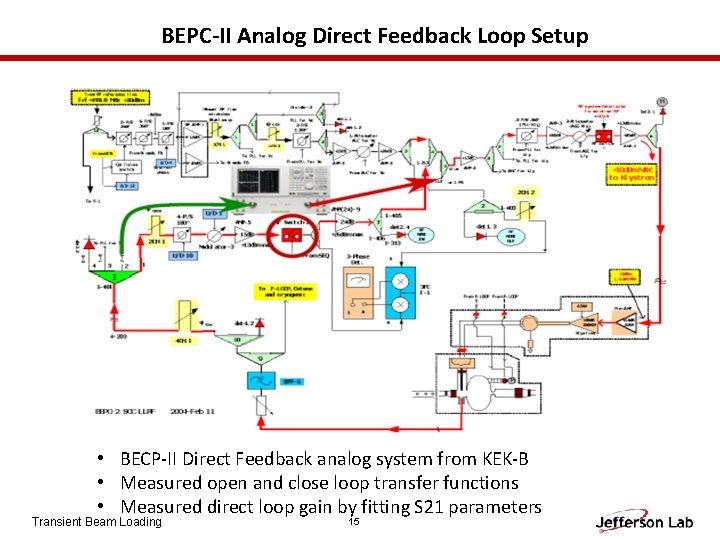
BEPC-II Analog Direct Feedback Loop Setup • BECP-II Direct Feedback analog system from KEK-B • Measured open and close loop transfer functions • Measured direct loop gain by fitting S 21 parameters Transient Beam Loading 15
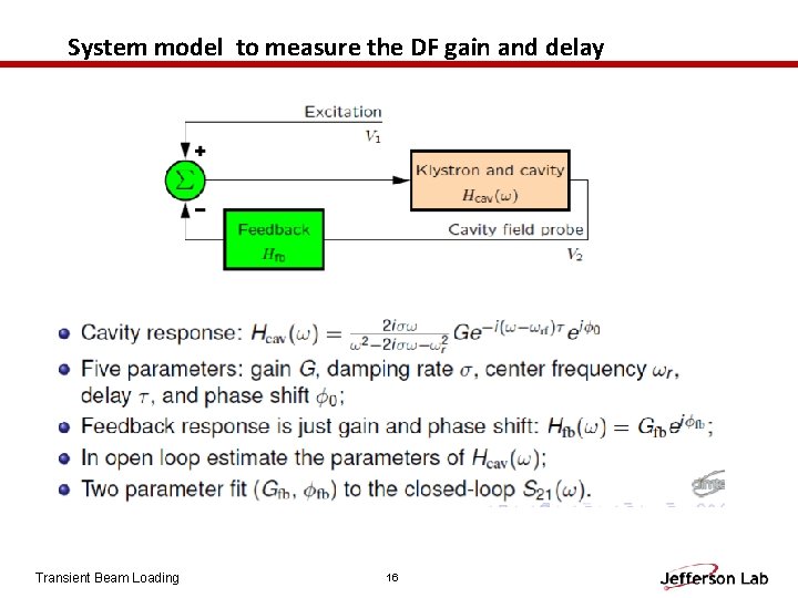
System model to measure the DF gain and delay Transient Beam Loading 16
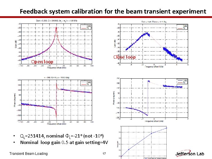
Feedback system calibration for the beam transient experiment Close loop Open loop • QL=251414, nominal FL=-21 o (not -10 o) • Nominal loop gain 0. 5 at gain setting=4 V Transient Beam Loading 17
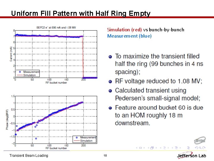
Uniform Fill Pattern with Half Ring Empty Simulation (red) vs bunch-by-bunch Measurement (blue) Transient Beam Loading 18
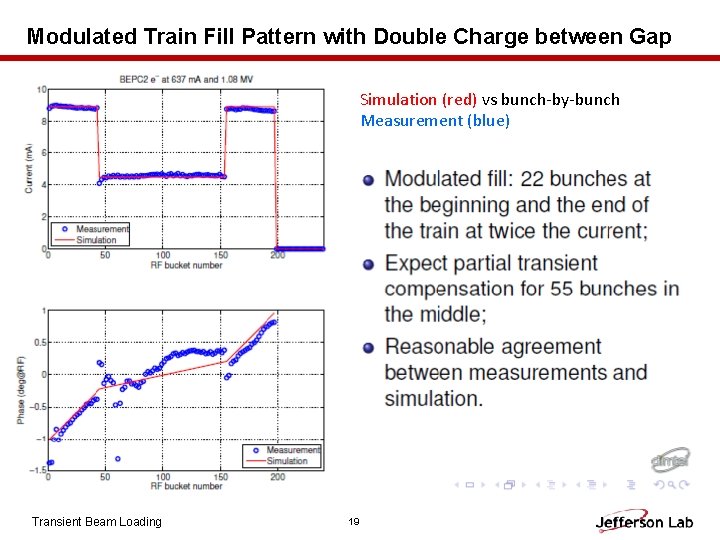
Modulated Train Fill Pattern with Double Charge between Gap Simulation (red) vs bunch-by-bunch Measurement (blue) Transient Beam Loading 19
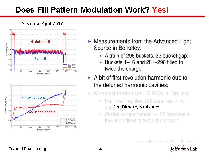
Does Fill Pattern Modulation Work? Yes! ALS data, April 2017 Modulated fill Even fill Phase transient See Dimetry’s talk next Reduced transient Transient Beam Loading 20
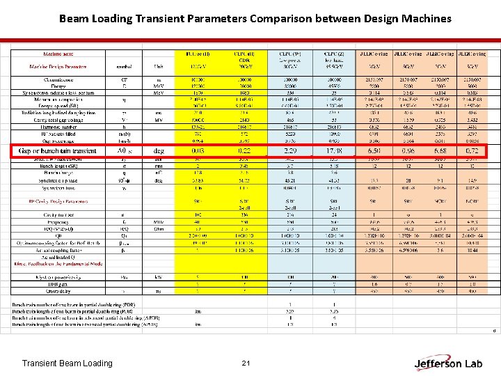
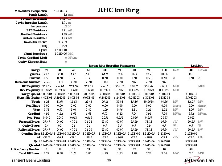
Beam Loading Transient Parameters Comparison between Design Machines Transient Beam Loading 21
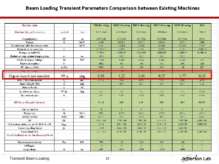
Beam Loading Transient Parameters Comparison between Existing Machines Transient Beam Loading 22
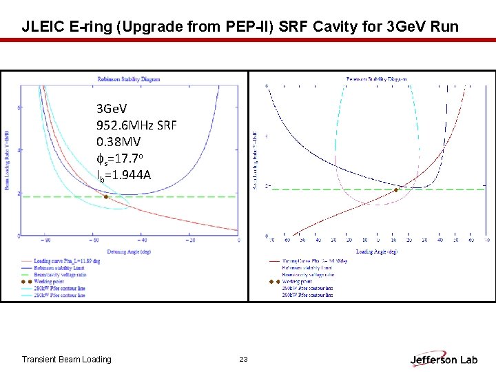
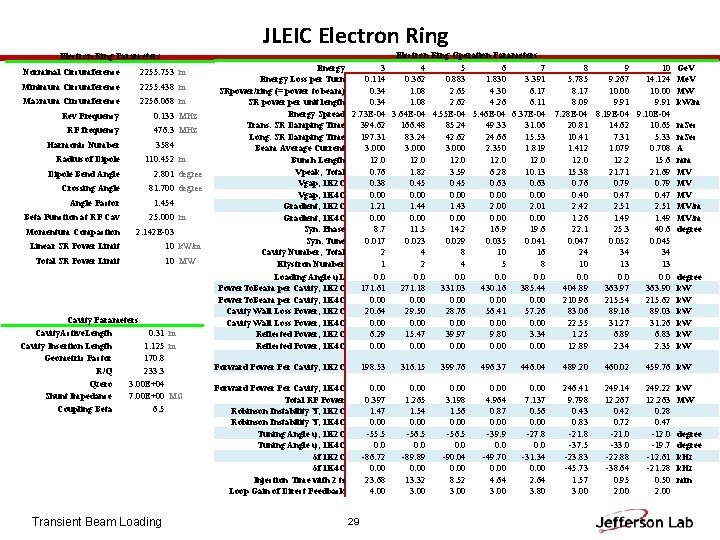
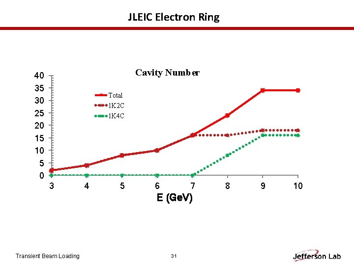
JLEIC E-ring (Upgrade from PEP-II) SRF Cavity for 3 Ge. V Run 3 Ge. V 952. 6 MHz SRF 0. 38 MV s=17. 7 o Ib=1. 944 A Transient Beam Loading 23
Summary • Transient beam loadings in an open bunch train gap or a short bunch train a large gap can create a large beam phase transient and voltage variation. Without a fast feedback (or feed forward) or extra stored energy from overhead klystron power or coupling cavity, beam could become unstable in large energy spread or even loss by Robinson instability • Count measures by large fast direct feedback, bunch-by-bunch feedback, feedforward in pulse mode, more klystron overhead (with linear response) power have been analyzed in steady state boundary conditions for the stable region. This tool also provides the RF control system designs for the future storage rings • Enhanced charge densities around the large gap or uneven bunch bucket fillings around short bunch train can mitigate these transient beam loading problems • BEPC-II transient beam loading experiment has provided an excellent test bed for the transient beam loading compensation technique and a benchmark for the steady-state analysis and bunch-by-bunch tracking simulations. Transient Beam Loading 24
Acknowledgment: Great thanks to the Institute of High Energy Physics, Beijing for the high priority arrangement of BECP-II’s beam time, particularly Dr. Qing and his staff Yuan Zhang, Junhui Yue, Jianping Dai, Jun Xing and all technical supports to get this experiment running smoothly and efficiently. Thanks also go to Dr. Dmitry Teytelman for his talent design on his company’s bunch-by-bunch feedback system, instrumentation support and on-line software simulation and analysis to quickly get our experiment results Transient Beam Loading 25
Backup Slides Transient Beam Loading 26
References 1. 2. 3. 4. 5. 6. 7. 8. 9. 10. 11. 12. 13. 14. K. L. F. Bane, K. Kubo, P. B. Wilson, SLAC, Stanford, CA 94309, USA, Compensating the Unequal Bunch Spacings in the NLC Damping Rings, Proceedings of EPAC 1993. J. M. Byrd etc. , Transient Bean loading Effects in Harmonic RF Systems for Light Sources, PRST-AB, Vol 5, 092001 (2002). D. Briggs, etc. , Computer Modelling of Bunch-by-bunch Feedback for the SLAC B-Factory Design, Proceedings of PAC 1991. http: //www-als. lbl. gov/index. php/beamlines/storage-ring-parameters. html Webpage of Advanced Light Source at Berkeley Lab J. Byrd, Simulation of the ALS Longitudimal Multibunch Feedback System, Proceedings of PAC 1993. B. Taylor etc. , The ALS Storage Ring RF System, Report of LBL-33291/UC-410/LGSGN-125, May 1993. J. M. Byrd etc. , Lifetime Increase Using Passive Harmonic Cavities in Synchrotron Light Sources, PRSTAB, Vol 4, 030701 (2001). J. Byrd etc. , Transient Beam Loading in the ALS Harmonic RF System, Proceedings of EPAC 2000, SLACPUB-9719. J. M. Byrd, etc. , Commissioning of a Higher Harmonic RF System for the Advanced Light Source, e. Scholarship of University of California, and LBNL, March 31, 2000. F. Pederson, A Novel RF Cavity Tuning Feedback Scheme for Heavy Beam Loading, IEEE Trans. on Nuclear Science, Vol. NS-32, No. 5, Oct. 1985. F. Pederson, IEEE Trans. Nuclear Science, Vol. NS-22, No. 3, June 1975, Proceedings of PAC 1975. P. Krejcik and F. Pederson etc. , RF Feedback for beam Loading Compensation in the SLC Damping Rings, Proceedings of PAC 1993. R. W. Robinson, CEA, Report No. CEAL-1010, 1964. G. Krafft etc. , Beam Loading Studies at CEBAF, Proceeding of LINAC 1990, Albuquerque, New Mexico, USA Transient Beam Loading 27
References 15. D. Boussard, PAC 1991, p 2447 16. Shaoheng Wang, Direct Feedback, unpublished, April, 2015. 17. S. Heifets and D. Teytelman, PRST-AB 10, 012804 (2007) 18. H. Wang, S. Wang, Derivation of the constant power contour lines in Robinson stability diagram, Note rewritten on January 13, 2016 19. P. B. Wilson, SLAC-PUB-6062, March 1993 20. J. M. Byrd, etc. , PRST-AB 5, 092001 (2002) 21. S. Koscielniak, Robinson-Type Stability Criteria for Beam and Cavity with Delayed, Voltageproportional Feedback, Particle Accelerators, Vol. 62, pp. 179 -214, 1999 22. J. T. Seeman, SLAC, PAC 1999 23. J. T. Seeman, SLAC-PUB-14677, 2008 24. M. Mc. Intosh, etc. SLAC, SLAC-PUB-10984, July, 2004 25. H. Wang, etc. Proceedings of IPAC 2016, MOPMY 003 26. D. Teytelman, Dimtel, Inc. , San Jose, CA, USA. “Transient beam loading in FCC-ee (Z)”, FCC Week 2017 27. P. Mc. Intosh, et. al. , EPAC 2004, PEP-II RF SYSTEM OPERATION AND PERFORMANCE 28. Dmitry Teytelman, PAC 05, Beam loading compensation for Super B-factories, Transient Beam Loading 28
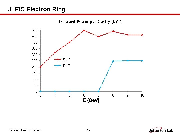
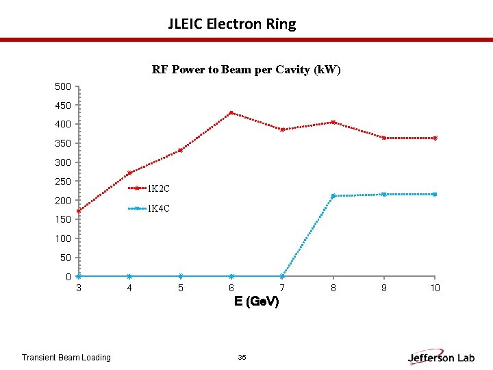
JLEIC Electron Ring Parameters Norminal Circumference 2255. 753 m Minimum Circumference 2255. 438 m Maxmum Circumference 2256. 068 m Rev Frequency 0. 133 MHz RF frequency 476. 3 MHz Harmonic Number Radius of Dipole 3584 110. 452 m Dipole Bend Angle 2. 801 degree Crossing Angle 81. 700 degree Angle Factor Beta Function at RF Cav Momentum Compaction 1. 454 25. 000 m 2. 142 E-03 Linear SR Power Limit Total SR Power Limit 10 k. W/m 10 MW Cavity Parameters Cavity. Active. Length 0. 31 m Cavity Insertion Length 1. 125 m Geometric Factor 170. 8 R/Q 233. 3 Qzero 3. 00 E+04 Shunt Impedance 7. 00 E+00 MΩ Coupling Beta 6. 5 Transient Beam Loading Electron Ring Operation Parameters Energy 3 4 5 6 7 Energy Loss per Turn 0. 114 0. 362 0. 883 1. 830 3. 391 SRpower/ring (= power to beam) 0. 34 1. 08 2. 65 4. 30 6. 17 SR power per unit length 0. 34 1. 08 2. 62 4. 26 6. 11 Energy Spread 2. 73 E-04 3. 64 E-04 4. 55 E-04 5. 46 E-04 6. 37 E-04 Trans. SR Damping Time 394. 62 166. 48 85. 24 49. 33 31. 06 Long. SR Damping Time 197. 31 83. 24 42. 62 24. 66 15. 53 Beam Average Current 3. 000 2. 350 1. 819 Bunch Length 12. 0 Vpeak, Total 0. 76 1. 82 3. 59 6. 28 10. 13 Vgap, 1 K 2 C 0. 38 0. 45 0. 63 Vgap, 1 K 4 C 0. 00 Gradient, 1 K 2 C 1. 21 1. 44 1. 43 2. 00 2. 01 Gradient, 1 K 4 C 0. 00 Syn. Phase 8. 7 11. 5 14. 2 16. 9 19. 6 Syn. Tune 0. 017 0. 023 0. 029 0. 035 0. 041 Cavity Number, Total 2 4 8 10 16 Klystron Number 1 2 4 5 8 Loading Angle ψL 0. 0 0. 0 Power. To. Beam per Cavity, 1 K 2 C 171. 61 271. 18 331. 03 430. 16 385. 44 Power. To. Beam per Cavity, 1 K 4 C 0. 00 Cavity Wall Loss Power, 1 K 2 C 20. 64 29. 50 28. 76 56. 41 57. 26 Cavity Wall Loss Power, 1 K 4 C 0. 00 Reflected Power, 1 K 2 C 6. 29 15. 47 39. 97 9. 80 3. 34 Reflected Power, 1 K 4 C 0. 00 8 9 10 Ge. V 5. 785 9. 267 14. 124 Me. V 8. 17 10. 00 MW 8. 09 9. 91 k. W/m 7. 28 E-04 8. 19 E-04 9. 10 E-04 20. 81 14. 62 10. 65 m. Sec 10. 41 7. 31 5. 33 m. Sec 1. 412 1. 079 0. 708 A 12. 0 12. 2 15. 6 mm 15. 38 21. 71 21. 69 MV 0. 76 0. 79 MV 0. 40 0. 47 MV 2. 42 2. 51 MV/m 1. 26 1. 49 MV/m 22. 1 25. 3 40. 6 degree 0. 047 0. 052 0. 045 24 34 34 10 13 13 0. 0 degree 404. 89 363. 97 363. 90 k. W 210. 96 215. 54 215. 62 k. W 83. 06 89. 16 89. 03 k. W 22. 55 31. 27 31. 26 k. W 1. 25 6. 89 6. 83 k. W 12. 89 2. 34 2. 35 k. W Forward Power Per Cavity, 1 K 2 C 198. 53 316. 15 399. 76 496. 37 446. 04 489. 20 460. 02 459. 76 k. W Forward Power Per Cavity, 1 K 4 C Total RF Power Robinson Instability Y, 1 K 2 C Robinson Instability Y, 1 K 4 C Tuning Angle ψ, 1 K 2 C Tuning Angle ψ, 1 K 4 C δf 1 K 2 C δf 1 K 4 C Injection Time with 2 ts Loop Gain of Direct Feedback 0. 00 0. 397 1. 47 0. 00 -55. 5 0. 0 -86. 72 0. 00 23. 68 4. 00 0. 00 1. 265 1. 54 0. 00 -56. 5 0. 0 -89. 89 0. 00 13. 32 3. 00 0. 00 3. 198 1. 56 0. 00 -56. 5 0. 0 -90. 04 0. 00 8. 52 3. 00 0. 00 4. 964 0. 87 0. 00 -39. 9 0. 0 -49. 70 0. 00 4. 64 3. 00 0. 00 7. 137 0. 56 0. 00 -27. 8 0. 0 -31. 34 0. 00 2. 64 3. 80 246. 41 9. 798 0. 43 0. 83 -21. 8 -37. 5 -23. 83 -45. 73 1. 57 3. 00 249. 14 12. 267 0. 42 0. 72 -21. 0 -33. 0 -22. 88 -38. 64 0. 95 2. 00 249. 22 12. 263 0. 28 0. 47 -12. 0 -19. 7 -12. 61 -21. 28 0. 50 2. 00 29 k. W MW degree k. Hz min
Momentum Compaction Bunch Length Cavity. Active. Length Cavity Insertion Length temperature BCS Resistance Residual Resistance Surface Resistance Geometric Factor R/Q Qzero Shunt Impedance Cavity Gradient Limit Cavity Klystron Ratio 6. 413 E-03 12 0. 157 1. 91 2 8. 91 4. 39 13. 3 217. 02 105. 2 1. 63 E+10 1. 72 E+06 8 8 Energy 20 gamma 22. 3 Current 0. 50 Harmonic Number 7174 RF frequency 952. 65 Rev Frequency 0. 13279 Energy Spread 3. 00 E-04 Phase Slip Factor 4. 40 E-03 Vpeak 6. 23 Syn. Phase 0. 00 Vgap 0. 78 Gradient 4. 95 Syn. Tune 0. 040 Forward Power 27. 47 Cavity Power 0. 4 Reflected Power 27. 47 Coupling Beta 3. 11 E+05 δf -32. 2 Qext 5. 24 E+04 Qloaded 5. 24 E+04 Active Cavity Number 8 Total RF Power 0. 22 30 33. 0 0. 50 7170 952. 64 0. 13286 3. 00 E-04 5. 49 E-03 11. 64 0. 00 0. 73 4. 62 0. 049 24. 00 0. 3 24. 00 3. 11 E+05 -34. 4 5. 24 E+04 16 0. 38 Transient Beam Loading mm m m K nΩ nΩ nΩ JLEIC Ion Ring MΩ MV/m 40 43. 6 0. 50 7168 952. 56 0. 13289 3. 00 E-04 5. 89 E-03 16. 63 0. 00 1. 04 6. 61 0. 053 49. 01 0. 6 49. 01 3. 11 E+05 -24. 1 5. 24 E+04 16 0. 78 Proton Ring Operation Parameters 50 60 70 80 54. 3 64. 9 75. 6 86. 3 0. 50 7168 952. 65 952. 70 952. 73 952. 75 0. 13290 0. 13291 0. 13292 3. 00 E-04 6. 07 E-03 6. 18 E-03 6. 24 E-03 6. 28 E-03 21. 44 26. 16 30. 83 35. 46 0. 00 0. 89 1. 09 0. 96 1. 11 5. 68 6. 93 6. 12 7. 04 0. 055 0. 056 36. 21 53. 89 42. 09 55. 69 0. 5 0. 7 36. 20 53. 89 42. 09 55. 69 3. 11 E+05 -28. 0 -23. 0 -26. 0 -22. 6 5. 24 E+04 5. 24 E+04 24 24 32 32 0. 87 1. 29 1. 35 1. 78 30 90 96. 9 0. 50 7168 952. 76 0. 13292 3. 00 E-04 6. 31 E-03 40. 0688 0. 00 1. 25 7. 96 0. 057 71. 11 0. 9 71. 11 3. 11 E+05 -20. 0 5. 24 E+04 32 2. 28 100 107. 6 0. 50 7168 952. 77 0. 13292 3. 00 E-04 6. 33 E-03 44. 66 0. 00 1. 12 7. 10 0. 057 56. 54 0. 7 56. 54 3. 11 E+05 -22. 4 5. 24 E+04 40 2. 26 Ge. V A Lead ion 40 Ge. V/u 44. 1 0. 50 A MHz MV degree MV MV/m k. W W k. Hz MW MHz 3. 00 E-04 5. 90 E-03 42. 27 0. 00 1. 06 6. 72 0. 053 50. 65 0. 7 50. 65 3. 11 E+05 -23. 7 5. 24 E+04 40 2. 0 MV degree MV MV/m k. W W k. Hz MW
JLEIC Electron Ring Cavity Number 40 35 30 25 20 15 10 5 0 Total 1 K 2 C 1 K 4 C 3 4 5 6 7 E (Ge. V) Transient Beam Loading 31 8 9 10
JLEIC Electron Ring Electron Beam Current (A) 3. 0 2. 0 1. 0 0. 0 3 4 5 6 7 E (Ge. V) Transient Beam Loading 32 8 9 10
JLEIC Electron Ring E (Ge. V) Transient Beam Loading 33

JLEIC Electron Ring Bunch Length (mm) 18 17 16 15 14 13 12 11 10 3 4 5 6 7 E (Ge. V) Transient Beam Loading 34 8 9 10
JLEIC Electron Ring E (Ge. V)
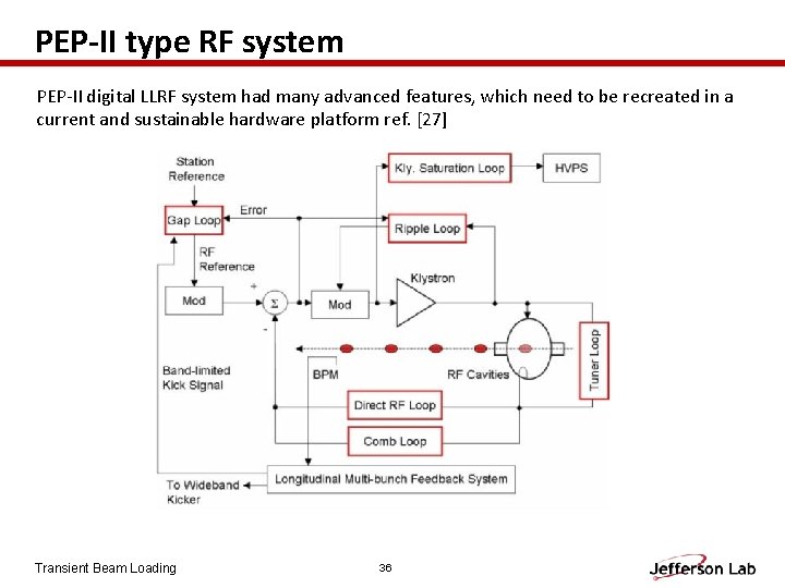
PEP-II type RF system PEP-II digital LLRF system had many advanced features, which need to be recreated in a current and sustainable hardware platform ref. [27] Transient Beam Loading 36
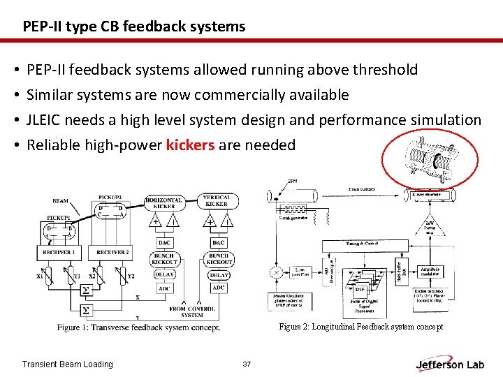
PEP-II type CB feedback systems • • PEP-II feedback systems allowed running above threshold Similar systems are now commercially available JLEIC needs a high level system design and performance simulation Reliable high-power kickers are needed Figure 2: Longitudinal Feedback system concept Transient Beam Loading 37
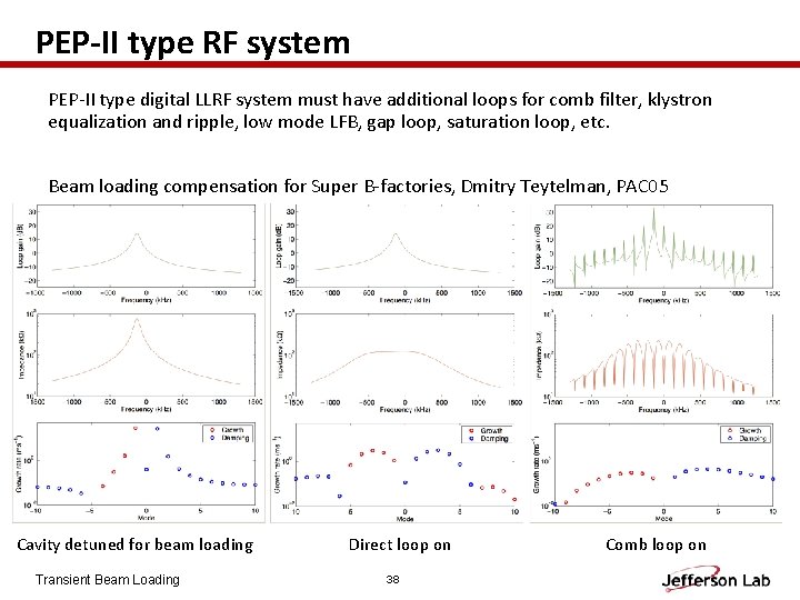
PEP-II type RF system PEP-II type digital LLRF system must have additional loops for comb filter, klystron equalization and ripple, low mode LFB, gap loop, saturation loop, etc. Beam loading compensation for Super B-factories, Dmitry Teytelman, PAC 05 Cavity detuned for beam loading Transient Beam Loading Direct loop on 38 Comb loop on
- Slides: 38