Status of the singlebunch feedback system for the

Status of the single-bunch feedback system for the SPS/LHC M. Pivi for C. Rivetta, J. Cesaratto, J. Fox, O. Turgut, S. Uemuda, W. Hofle, U. Wehrle, K. Li, H. Bartosik, G. Rumolo, M. Furman, S. De Santis, R. Secondo, J. -L. Vay LARP collaboration: SLAC, CERN, LBNL 27 June 2012 - ICE Meeting, CERN

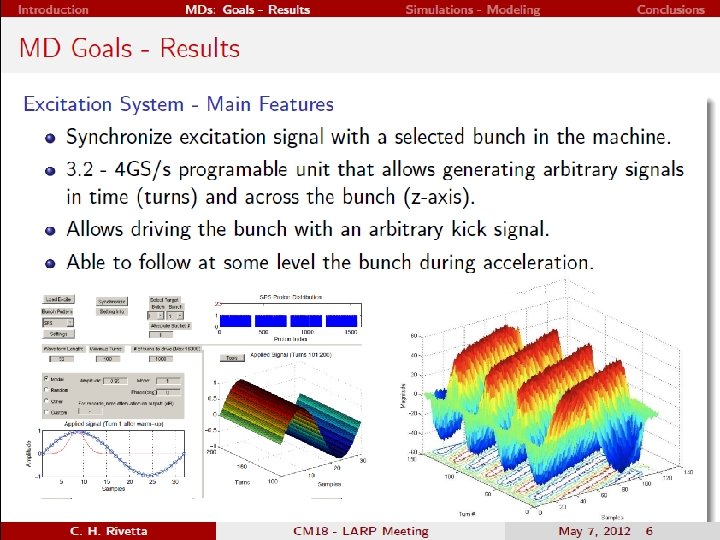
Single-bunch Feedback system concept • TMCI and electron cloud cause intra-bunch motion in the SPS. • LARP / CERN design of a feedback: measure the position of slices in a bunch and control each slice individually by applying electric fields • Need for high bandwidth to sufficiently sample the bunch

Feedback system ongoing work • Driving the beam during Machine Development MD studies • Code development to include a single-bunch feedback system • Under development: – High bandwidth kicker design – Analog equalizer for the pick-up system • Design Report

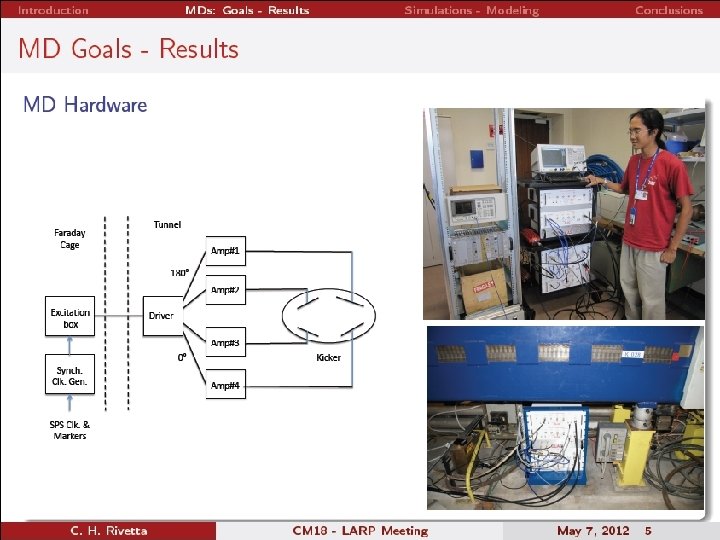
Machine Development’s goals • MDs goals: Install hardware in the SPS tunnel/ Faraday cage and drive the beam (i. e. excite the beam and measure its response) • Evaluate a method to time properly the kicker signal with the bunch. Actually installed in the SPS beam line (Linnecar): – Kicker: exponentially tapered pickup and flipped around, with 200 MHz response transfer function

200 MHz kicker in SPS Hardware installed in the SPS Beam excitation system in Faraday cage

Potential SPS location for the singlebunch feedback system installation

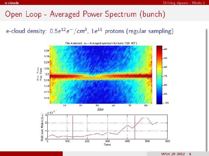
MD April results: excited bunch multimode motion. 1 / 2 1. Precisely timed the kick with a Single Bunch in the machine 2. Swept a 200 MHz sine wave excitation signal from a tune of 0. 18 through 0. 19 The signal is swept from turn 2000 -14000. RMS vertical motion delta signal from pick-up shows modal composition at turn 4576 Qx=0. 183, Qs~0. 005 Power spectrum (of 1 bunch slice): excitation of mode 0 at turn 4000 and weekly of mode 1 at Turn 11000.

MD April results: excited bunch multimode motion. 2 / 2 Lower bunch chromaticity, swept the excitation signal from a tune of 0. 175 through 0. 188. The signal is swept here from turn 2000 -17000. Qx=0. 181, Qs~0. 004 RMS vertical motion Delta signal from pick-up shows modal composition at turn 13376 Power spectrum (of 1 bunch slice): excitation of modes 0, 1, 2, 3 from turn 9000 to 13000. No -1 mode observed.

animations C. Rivetta, J. Cesaratto, M. Pivi

MD April • All machine data taken to date has been with a single bunch. • Look forward to measurements exciting a particular bunch in a multi-bunch fill.
 Limitations in filling patterns (ECI) Diagnostic")
Past work Experimental observations Limitation in intensity (TMCI) Limitations in filling patterns (ECI) Diagnostic tools: BPM, headtail monitors, emittance monitors, mode analysis Stabilisation on a bunch-by-bunch level by transverse damper High bandwidth feedback (some examples) Y. Chin et al. : Intra-bunch feedback system in Jparc (Jp), 50 MHz J. Thomson: simplified and idealised feedback model → minimum bandwidth of 300 MHz K. Ohmi: high bandwidth feedback simulations → 700 MHz M. Pivi: implementation of a realistic feedback system into CMAD Kevin Li, CERN

Simulation Code Development • Realistic single-bunch feedback system have been implemented in Head-Tail, C-MAD, Warp simulation codes. • At SLAC: – First implemented C-MAD (by Pivi, Rivetta): • Developed and tested feedback system in C-MAD, then the routine has been copied into Head-Tail – Head-Tail developed (by Pivi, Li) to include single-bunch feedback system

Plans for code utilization The feedback system is simulated with: • Head-Tail which comes with different options for the SPS: electron cloud, TMCI and advanced impedances model for the SPS. • C-MAD parallel code (M. Pivi et al. ): electron cloud instability, Intra-Beam Scattering IBS, and allows to upload the full SPS lattice from MAD for more realistic simulations.

Feedback system design C. Rivetta

Code development: Feedback Design Intra-bunch feedback includes: • Main Blocks – – – Processing Channel: FIR-IIR filters (diagonal by now) Filter receiver – (Pick-up, cable, receiver, ADC) Filter kicker – (DAC, Amplifier, Cables, Kicker) Includes saturation at the receiver and amplifier The system has finite dynamic range and realistic input noise floor • Bunch sampling frequency is an adjustable parameter • Noise-Signal-Perturbation injection: – Receiver – Amplifier • Measurement of absolute vertical displacement and dipole motion • 7 input files characterize the feedback system • Frequency bandwidth: example 200 MHz / 1000 Mhz

Multi-particle simulation codes • The multi-particle simulation codes solves:
 The beam is stable")
Feedback system reduced model – Rootlocus (note: no electron clouds) The beam is stable within the boundary. Exceeding the ideal feedback gain may induce the beam unstable. Eigenvalues for increased gain of the feedback system.

Kicker frequency response C. Rivetta Different kicker bandwidths implemented in simulations. Kicker actually in SPS has BW=200 MHz.

Codes comparison: feedback in “closed loop”, no cloud, bunch has initial displacement. Vertical position (m) BW=200 MHz, Head-Tail gain = 8. 4 e-3 (C-MAD G = 0. 75) turns Good agreement

SPS: Feedback OFF E-cloud density: 5 e 11 e/m 3, beam current 1. 1 e 11 ppb. SPS – single-bunch feedback OFF Increase in vertical beam emittance a factor 4

Presentation Title Page 23

Presentation Title Page 24

Presentation Title Page 25

Spectral mode analysis: Feedback OFF Evolution of vertical position of bunch slices during 512 turns, e-cloud density 6 e 11 e/m 3 Bunch oscillation modes as a function of cloud density
 E-cloud density:")
SPS: Feedback ON Preliminary Tests SPS – feedback in Closed Loop” (ON) E-cloud density: 0. 5 e 12 e/m 3, 1. 1 e 11 ppb, feedback fixed gain 0. 5, BW=200 -1000 MHz

Initial tests 500 MHz Perturbation: Electron cloud 1000 MHz Kevin Li, C. Rivetta, M. Pivi

Feedback power required Kick applied to individual bunch slices by the feedback system Feedback ON: no electron cloud � 10 -5 Feedback ON: ecloud density 5 e 11/m 3 � 10 -5 Same scale: Low feedback power is required to stabilize the beam in the presence of electron cloud M. Pivi, C. Rivetta, Kevin Li

Report in preparation • The LARP working group will provide CERN with the design report and suggested kicker(s) implementations • CERN will build the feedback system – resources needed at CERN (with W. Hofle, LIU)

Simulation plan Mauro Pivi, CERN/SLAC
 • Use Head-Tail: simulate a Damper-like feedback with c� 0 for")
Simulation plan (continue) • Use Head-Tail: simulate a Damper-like feedback with c� 0 for TMCI and electron cloud (see Alexey Burov presentation 13/06/12) • Space charge effect with electron cloud: investigate the observed (Landau) damping effect introduced by space charge

Feedback System Team* *LARP collaboration: SLAC, LBNL, CERN • Beam excitation and MD tests: Rivetta, Fox, Cesaratto, Hofle, Uemuda, Turgut, Pivi, Wehrle • Simulations: Rivetta, Pivi, Li, Secondo, Vay – Head-Tail development: Pivi, Li • Kicker design: De Santis, Cesaratto • Feedback design: all

Summary • Beam excitation and measurements in the SPS show intra-bunch motion with modes excited • Development of codes (recently Head-Tail) to include single-bunch feedback system – very promising initial results from simulations: – A bandwidth of 500 MHz and low power levels are required to stabilize the beam with electron cloud interactions • Design Report for SPS prototype
 E-cloud density:")
SPS: Feedback ON Preliminary Tests SPS – feedback in Closed Loop” (ON) E-cloud density: 0. 5 e 12 e/m 3, 1. 1 e 11 ppb, feedback fixed gain 0. 5, BW=200 -1000 MHz

Simulation plan Mauro Pivi, CERN/SLAC

Simulation plan and feedback design • In particular, important steps are: – Optimize bunch sampling: vary from 8 to 64 (so far, used ideally 64). Smaller the number of samples, less expensive the feedback. – Include noise in the receiver/kicker – Include SPS realistic MAD lattice – Iterate on feedback design

Kicker available in SPS • Kicker: exponentially tapered pickup and flipped around, with 200 MHz response transfer function. – Tapered for frequency response, smooth the zeroes, but keep 50 Ohms along entire length! • See paper by Linnecar
- Slides: 39