
Status of HL2 A Team Presented by Longwen
Status of HL-2 A Team (Presented by Longwen Yan) Southwestern Institute of Physics, Chengdu, China Presentation for IEA PD and LT activities on May 21, 2007
OUTLINE • • Introduction of HL-2 A tokamak Auxiliary Heating & Fueling Systems Diagnostic systems Experimental progress Ø Ø Ø • • Results of divertor and high density experiments Results of SMBI fueling with LN temperature Results of GAM zonal flows Results of the ECRH with power of 2 MW Disruption mitigation and MHD mode coupling Conclusions Experimental Plan in 2007 Modification for HL-2 A
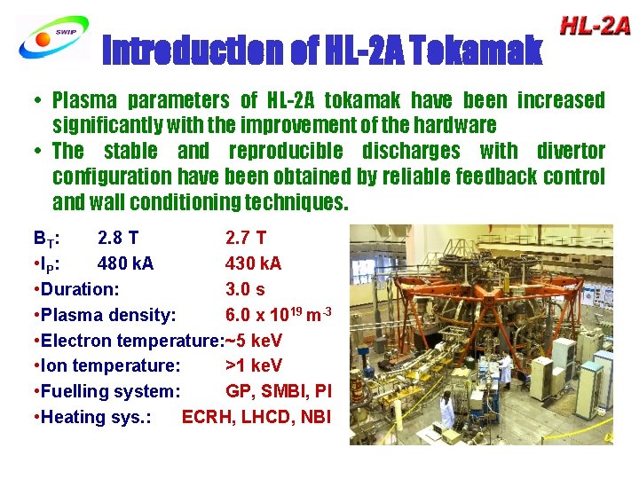
Introduction of HL-2 A Tokamak • Plasma parameters of HL-2 A tokamak have been increased significantly with the improvement of the hardware • The stable and reproducible discharges with divertor configuration have been obtained by reliable feedback control and wall conditioning techniques. BT : 2. 8 T 2. 7 T • IP: 480 k. A 430 k. A • Duration: 3. 0 s • Plasma density: 6. 0 x 1019 m-3 • Electron temperature: ~5 ke. V • Ion temperature: >1 ke. V • Fuelling system: GP, SMBI, PI • Heating sys. : ECRH, LHCD, NBI
Auxiliary Heating & Current Drive The red values are for the next phase
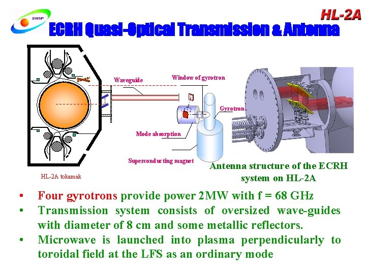
ECRH Quasi-Optical Transmission & Antenna Waveguide Window of gyrotron Gyrotron Mode absorption Superconducting magnet HL-2 A tokamak • • • Antenna structure of the ECRH system on HL-2 A Four gyrotrons provide power 2 MW with f = 68 GHz Transmission system consists of oversized wave-guides with diameter of 8 cm and some metallic reflectors. Microwave is launched into plasma perpendicularly to toroidal field at the LFS as an ordinary mode
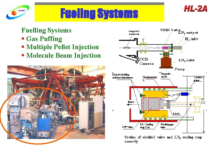
Fueling Systems Fuelling Systems § Gas Puffing § Multiple Pellet Injection § Molecule Beam Injection
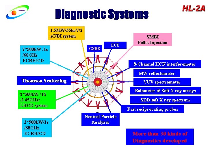
Diagnostic Systems 1. 5 MW/55 ke. V/2 s/NBI system 2*500 k. W /1 s /68 GHz ECRH/CD CXRS ECE SMBI Pellet Injection 8 -Channel HCN interferometer MW reflectometer Thomson Scattering VUV spectrometer Bolometer & Soft X ray arrays 2*500 k. W /1 S /2. 45 GHz/ LHCD system 2*500 k. W/1 s /68 GHz ECRH/CD SDD soft X ray spectrum Fast reciprocating probes Neutral Particle Analyzer More than 30 kinds of Diagnostics developed
OUTLINE • • Introduction of HL-2 A Tokamak Auxiliary Heating & Fueling Systems Diagnostic systems Experimental progress Ø Ø Ø • • Results of divertor and high density experiments Results of SMBI with LN temperature Results of GAM zonal flows Results of 2 MW ECRH Disruption mitigation and MHD mode coupling Conclusions Experimental Plan in 2007 Modification for HL-2 A
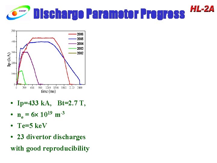
Discharge Parameter Progress • Ip=433 k. A, Bt=2. 7 T, • ne = 6 1019 m-3 • Te=5 ke. V • 23 divertor discharges with good reproducibility
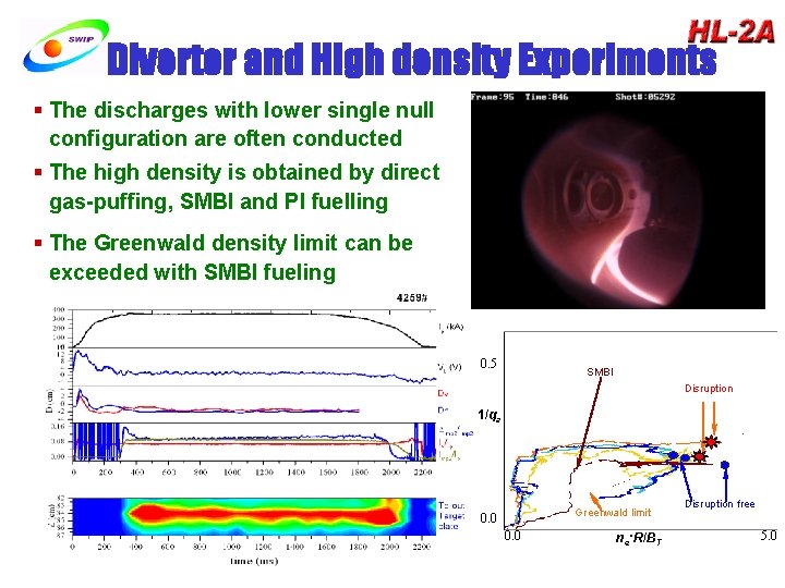
Divertor and High density Experiments § The discharges with lower single null configuration are often conducted § The high density is obtained by direct gas-puffing, SMBI and PI fuelling § The Greenwald density limit can be exceeded with SMBI fueling 0. 5 SMBI Disruption 1/qa Greenwald limit 0. 0 ne·R/BT Disruption free 5. 0
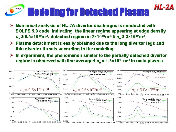
Modeling for Detached Plasma Ø Numerical analysis of HL-2 A divertor discharges is conducted with SOLPS 5. 0 code, indicating the linear regime appearing at edge density ne ≤ 0. 5× 10¹⁹ m-3, detached regime in 2× 10¹⁹ m-3 ≤ ne ≤ 3× 10¹⁹ m-3 Ø Plasma detachment is easily obtained due to the long divertor legs and thin divertor throats according to the modeling. Ø In experiment, the phenomenon similar to the partially detached divertor regime is observed with line averaged ne = 1. 5× 10¹⁹ m-3 in main plasma. ne = 0. 5× 10¹⁹ m-3 ne = 2. 5× 10¹⁹ m-3 ne = 3. 0× 1019 m-3
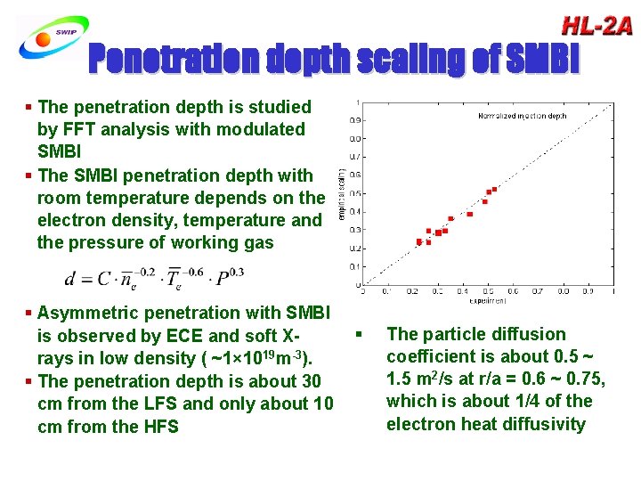
Penetration depth scaling of SMBI § The penetration depth is studied by FFT analysis with modulated SMBI § The SMBI penetration depth with room temperature depends on the electron density, temperature and the pressure of working gas § Asymmetric penetration with SMBI is observed by ECE and soft Xrays in low density ( ~1× 10¹⁹ m-3). § The penetration depth is about 30 cm from the LFS and only about 10 cm from the HFS § The particle diffusion coefficient is about 0. 5 ~ 1. 5 m 2/s at r/a = 0. 6 ~ 0. 75, which is about 1/4 of the electron heat diffusivity
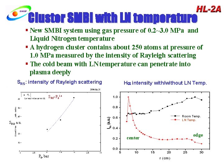
Cluster SMBI with LN temperature § New SMBI system using gas pressure of 0. 2~3. 0 MPa and Liquid Nitrogen temperature § A hydrogen cluster contains about 250 atoms at pressure of 1. 0 MPa measured by the intensity of Rayleigh scattering § The cold beam with LN temperature can penetrate into plasma deeply SRS: intensity of Rayleigh scattering H intensity with/without LN Temp. SRS~P 01. 4 Room Temp. LN Temp. SRS, a. u. center P 0, bar edge
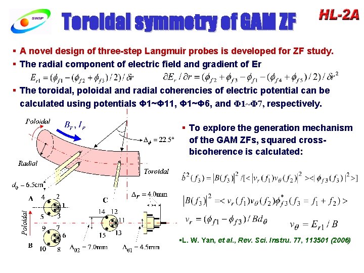
Toroidal symmetry of GAM ZF § A novel design of three-step Langmuir probes is developed for ZF study. § The radial component of electric field and gradient of Er § The toroidal, poloidal and radial coherencies of electric potential can be calculated using potentials Φ 1~Φ 11, Φ 1~Φ 6, and Φ 1~Φ 7, respectively. § To explore the generation mechanism of the GAM ZFs, squared crossbicoherence is calculated: §L. W. Yan, et al. , Rev. Sci. Instru. 77, 113501 (2006)
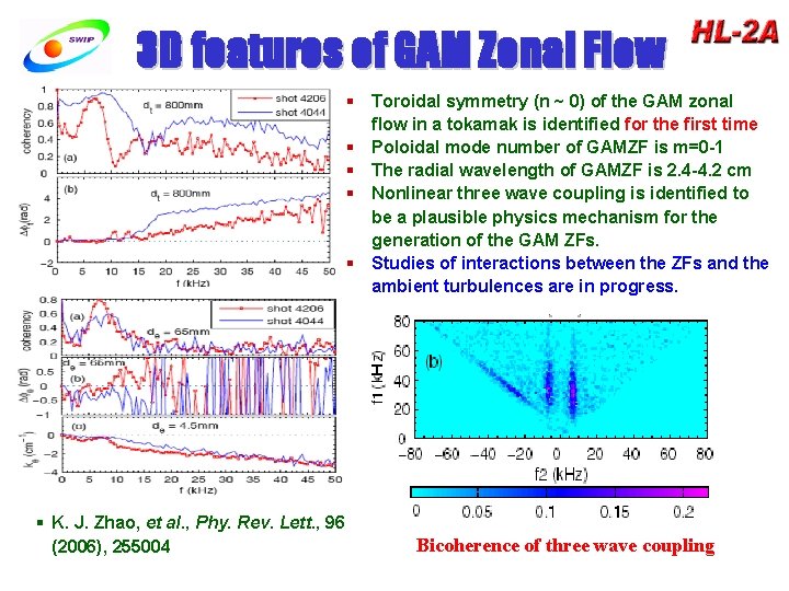
3 D features of GAM Zonal Flow § Toroidal symmetry (n ~ 0) of the GAM zonal flow in a tokamak is identified for the first time § Poloidal mode number of GAMZF is m=0 -1 § The radial wavelength of GAMZF is 2. 4 -4. 2 cm § Nonlinear three wave coupling is identified to be a plausible physics mechanism for the generation of the GAM ZFs. § Studies of interactions between the ZFs and the ambient turbulences are in progress. § K. J. Zhao, et al. , Phy. Rev. Lett. , 96 (2006), 255004 Bicoherence of three wave coupling
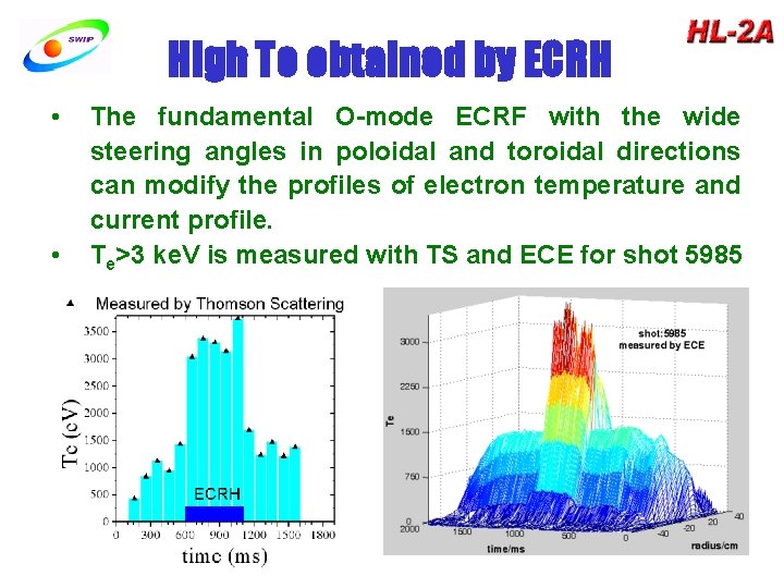
High Te obtained by ECRH • • The fundamental O-mode ECRF with the wide steering angles in poloidal and toroidal directions can modify the profiles of electron temperature and current profile. Te>3 ke. V is measured with TS and ECE for shot 5985
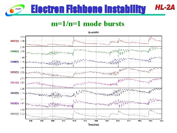
Electron Fishbone Instability m=1/n=1 mode bursts
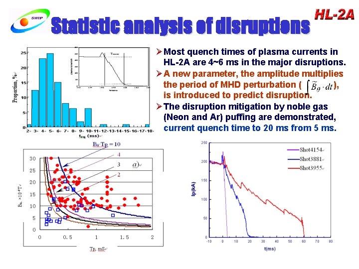
Statistic analysis of disruptions ØMost quench times of plasma currents in HL-2 A are 4~6 ms in the major disruptions. ØA new parameter, the amplitude multiplies the period of MHD perturbation ( ), is introduced to predict disruption. ØThe disruption mitigation by noble gas (Neon and Ar) puffing are demonstrated, current quench time to 20 ms from 5 ms.
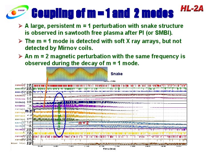
Coupling of m = 1 and 2 modes Ø A large, persistent m = 1 perturbation with snake structure is observed in sawtooth free plasma after PI (or SMBI). Ø The m = 1 mode is detected with soft X ray arrays, but not detected by Mirnov coils. Ø An m = 2 magnetic perturbation with the same frequency is observed during the decay of m = 1 mode. m=1 Coupling region Snake m=2
Summary § Maximum parameters: 433 k. A/2. 7 T/6 x 1019 m-3/5 ke. V/3 s/ § A penetration depth scaling of SMBI is revealed. The cluster SMBI with LNT can penetrate deeper. The particle diffusion coefficient of modulated SMBI is 0. 5 -1. 5 m 2/s. § 3 -D features of GAM ZFs are determined with novel 3 -step Langmuir probes for the first time. The poloidal and toroidal symmetries (m=0~1, n = 0) of the low frequency (7~9 k. Hz) electric potential and field are simultaneously observed. § Electron fishbone is observed with the ECRH of 2 MW/68 GHz § A large, persistent m = 1 perturbation with snake structure is observed after PI (or SMBI). § A new parameter of magnetic perturbation is introduced to predict the disruption. The noble gas injection successfully increase the current quench time to 20 ms from 5 ms. § The fully or partially detached divertor is easy occurrence, even if in medium density. The numerical simulation results are in agreement with experimental ones.
Confinement, transport & turbulence study in 2007 • H-mode physics with ECRH (2 MW) and LHCD (0. 5 MW) • Zonal flow mechanism with GAM and near zero frequencies • Thermal transport by modulated ECRH;nonlocal thermal transport via ECRH and SMBI • ITB with off-axis heating and SMBI • Impurity transport using LBO of Ti,Al,Mo. • Optimization of density profile by PI and MBI. • Density limit using mixed fuelling technique by GP + PI or GP + PI + MBI
MHD instability, disruption & its mitigation study in 2007 • MHD stabilities in low q (q < 3) discharges • Seed island suppression and sawteeth control by ECCD • ELM features in H-mode discharge • Disruption mitigation using the MBI of argon, impurity injection by LBO • Database for disruption prediction • Sawtooth activities during ECRH • Correlation between MHD activities and confinement • Instabilities induced by energetic electrons

Boundary and divertor physics • Wall conditioning using siliconization and boronization • First mirror and its properties • Radiative and pumped divertor • Temperature and density fluctuations • Detachment physics in divertor chamber
Heating and Current Drive • Optimization of heating and current drive for ECRF with 1~2 MW • Synergy of ECCD & LHCD • NBI heating with power 1. 5 MW • ITB comparison among HL-2 A, TEXTOR and T-10
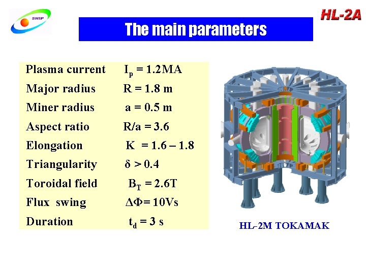
The main parameters Plasma current Ip = 1. 2 MA Major radius R = 1. 8 m Miner radius a = 0. 5 m Aspect ratio R/a = 3. 6 Elongation Κ = 1. 6 – 1. 8 Triangularity δ > 0. 4 Toroidal field BT = 2. 6 T Flux swing ΔΦ= 10 Vs Duration td = 3 s HL-2 M TOKAMAK
Thank you for your attention !
- Slides: 26