
Stato del progetto RICH di LHCb CSN 1
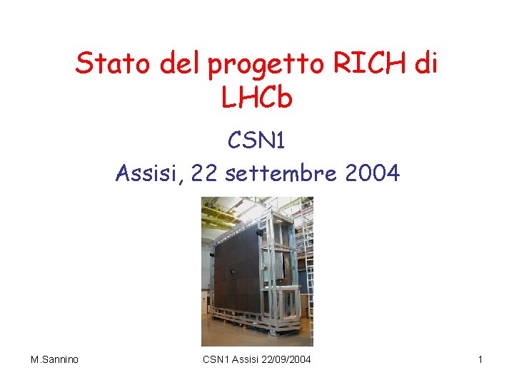
Stato del progetto RICH di LHCb CSN 1 Assisi, 22 settembre 2004 M. Sannino CSN 1 Assisi 22/09/2004 1
Rivelatori RICH di LHCb Identificazione delle particelle su intervallo 1 – 100 Ge. V/c mediante 2 rivelatori RICH 1: riprogettazione completa come da nuovo TDR LHcb light EDR presentato il 31/8 u. s. RICH 2: SOVRASTRUTTURA Essenzialmente come da TDR originario dei Rich INSTALLAZIONE DEI FOTORIVELATORI modificata M. Sannino Causata da : richieste per miglioramento livello trigger L 1 ( = 0. 15 Tm nella regione di “tracking”) Riduzione materiale nella accettanza dello Spettrometro Sovrastruttura costruita Finestre di ingresso e uscita installate Photon Funnel installati Specchi in Vetro (Pyrex / Simax) in corso di fabbricazione Beam Pipe installata CSN 1 Assisi 22/09/2004 2
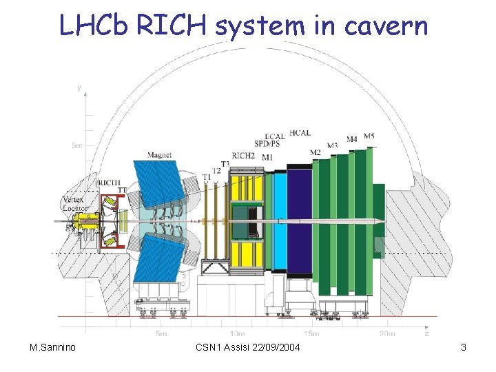
LHCb RICH system in cavern M. Sannino CSN 1 Assisi 22/09/2004 3
Impegni italiani nei RICH Genova : Rich 2 § alloggiamento fotorivelatori (inclusa trasmissione segnali a L 0 e raffreddamento design e componenti in parte utilizzati anche per Rich 1) § ECS Alte Tensioni Milano: Ø Rich 1 § Aerogel e relativi telai per l’installazione Ø § § § Rich 2 schermo magnetico consegna al CERN ottobre 2004 ottica (test, allineamento) schede distribuzione alta e bassa tensione M. Sannino CSN 1 Assisi 22/09/2004 4
Overview of RICH 1 – Changes since RICH TDR 1. Addition of Plane Mirrors to allow HPDs to be located where iron shields can be used 2. Vertical optical layout to allow shields to act as pole pieces for Level-1 trigger field 3. Reduction of material in LHCb acceptance Beryllium spherical mirrors Mirror supports outside acceptance Eliminate entrance window by sealing to VELO tank TDR: 14% X 0 M. Sannino Now: 7. 3% X 0 CSN 1 Assisi 22/09/2004 5
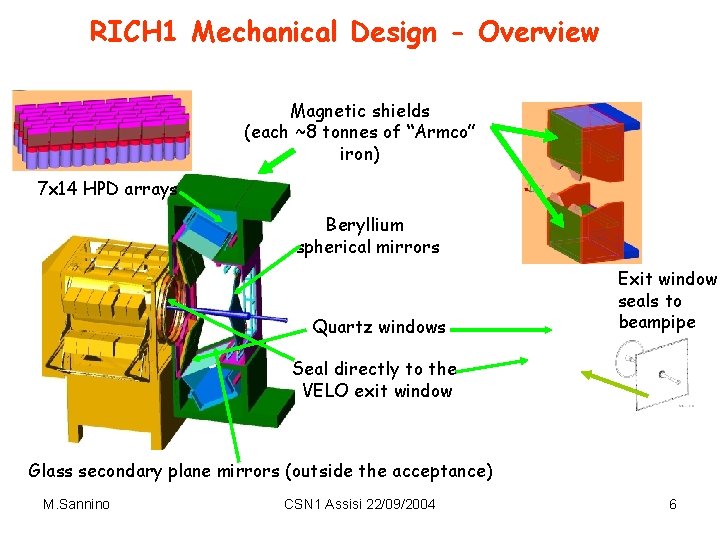
RICH 1 Mechanical Design - Overview Magnetic shields (each ~8 tonnes of “Armco” iron) 7 x 14 HPD arrays Beryllium spherical mirrors Quartz windows Exit window seals to beampipe Seal directly to the VELO exit window Glass secondary plane mirrors (outside the acceptance) M. Sannino CSN 1 Assisi 22/09/2004 6
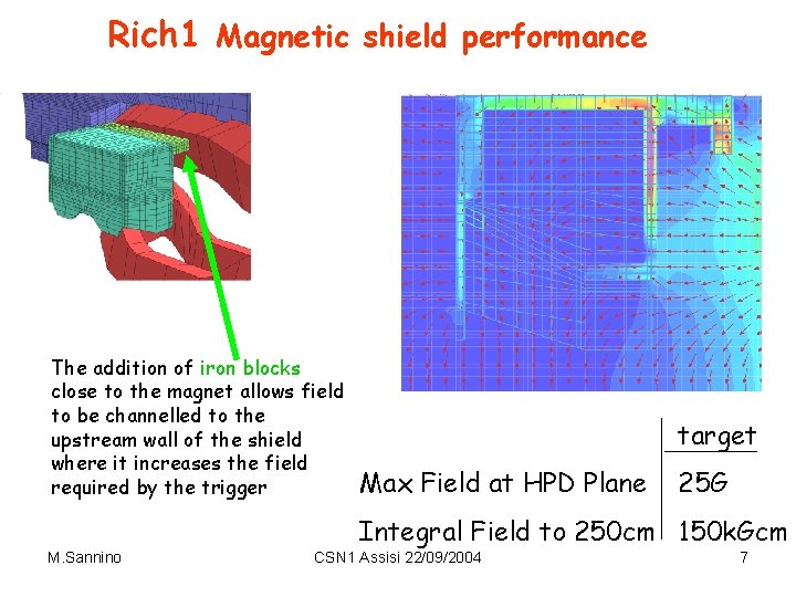
Rich 1 Magnetic shield performance The addition of iron blocks close to the magnet allows field to be channelled to the upstream wall of the shield where it increases the field required by the trigger target Max Field at HPD Plane 25 G Integral Field to 250 cm 150 k. Gcm M. Sannino CSN 1 Assisi 22/09/2004 7
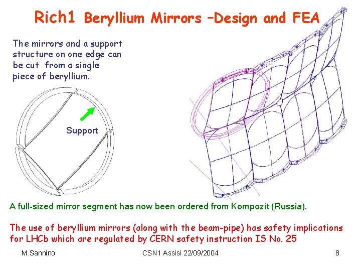
Rich 1 Beryllium Mirrors –Design and FEA The mirrors and a support structure on one edge can be cut from a single piece of beryllium. Support A full-sized mirror segment has now been ordered from Kompozit (Russia). The use of beryllium mirrors (along with the beam-pipe) has safety implications for LHCb which are regulated by CERN safety instruction IS No. 25 M. Sannino CSN 1 Assisi 22/09/2004 8
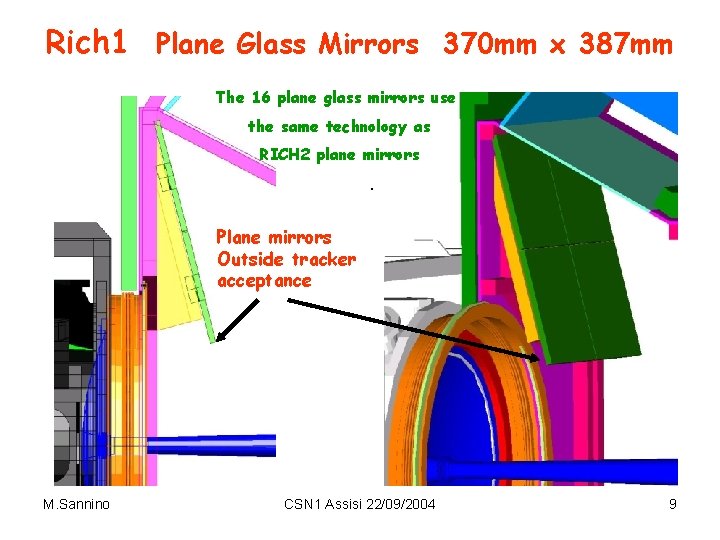
Rich 1 Plane Glass Mirrors 370 mm x 387 mm The 16 plane glass mirrors use the same technology as RICH 2 plane mirrors. Plane mirrors Outside tracker acceptance M. Sannino CSN 1 Assisi 22/09/2004 9
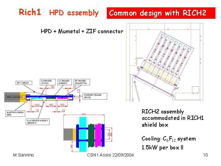
Rich 1 HPD assembly Common design with RICH 2 HPD + Mumetal + ZIF connector RICH 2 assembly accommodated in RICH 1 shield box Cooling: C 6 F 12 system 1. 5 k. W per box !! M. Sannino CSN 1 Assisi 22/09/2004 10
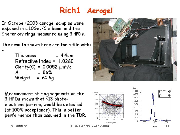
Rich 1 Aerogel In October 2003 aerogel samples were exposed in a 10 Gev/C beam and the Cherenkov rings measured using 3 HPDs. The results shown here are for a tile with: Thickness = 4. 4 cm Refractive Index = 1. 0280 Clarity(C) = 0. 0052 m 4/c A = 86% Weight = 60. 6 g Measurement of ring segments on the 3 HPDs shows that ~13 photoelectrons per ring would be detected (at 100% acceptance). This is better performance than assumed in the TDR. M. Sannino CSN 1 Assisi 22/09/2004 11
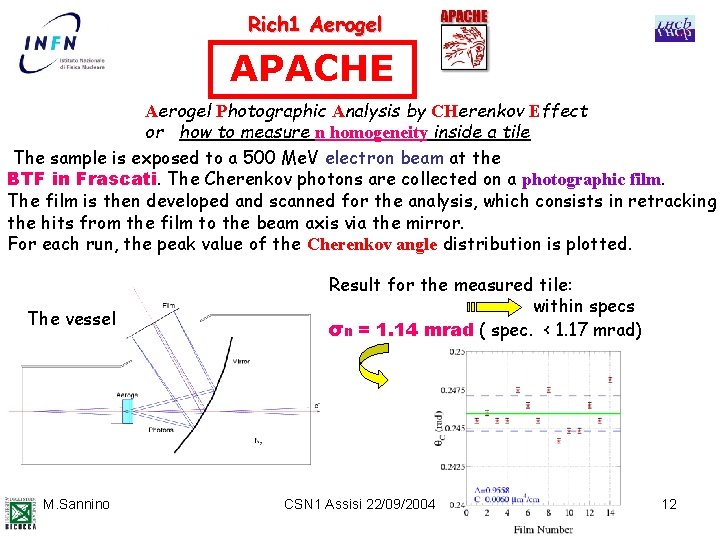
Rich 1 Aerogel APACHE Aerogel Photographic Analysis by CHerenkov Effect or how to measure n homogeneity inside a tile The sample is exposed to a 500 Me. V electron beam at the BTF in Frascati. The Cherenkov photons are collected on a photographic film. The film is then developed and scanned for the analysis, which consists in retracking the hits from the film to the beam axis via the mirror. For each run, the peak value of the Cherenkov angle distribution is plotted. The vessel M. Sannino Result for the measured tile: within specs σn = 1. 14 mrad ( spec. < 1. 17 mrad) CSN 1 Assisi 22/09/2004 12
Rich 1 Aerogel § Preseries production : 6 liters in 3 tiles 20 x 5 cm 3 delivered end June ’ 04 refractive index: 1. 0305, 1. 0309, 1. 0316, clarity : 0. 0054, 0. 0056, 0. 0062 m § Final contract in preparation (2 preserie tiles can be regarded as final ) § 20 l should be produced by end 2004 beginning 2005 M. Sannino CSN 1 Assisi 22/09/2004 13
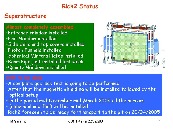
Rich 2 Status Superstructure Almost completely assembled • Entrance Window installed • Exit Window installed • Side walls and top covers installed • Photon Funnels installed • Spherical Mirrors Plates installed • Beam Pipe just installed last week • Quartz Windows installed Still to be done • A complete gas leak test is going to be performed • After that the magnetic shielding will be installed followed by the • optical setup • In the period mid-December mid-March 2005 all the mirrors • (spherical and flat) will be installed • Rich 2 foreseen to be ready for transport to the pit on 20/04/2005 M. Sannino CSN 1 Assisi 22/09/2004 14
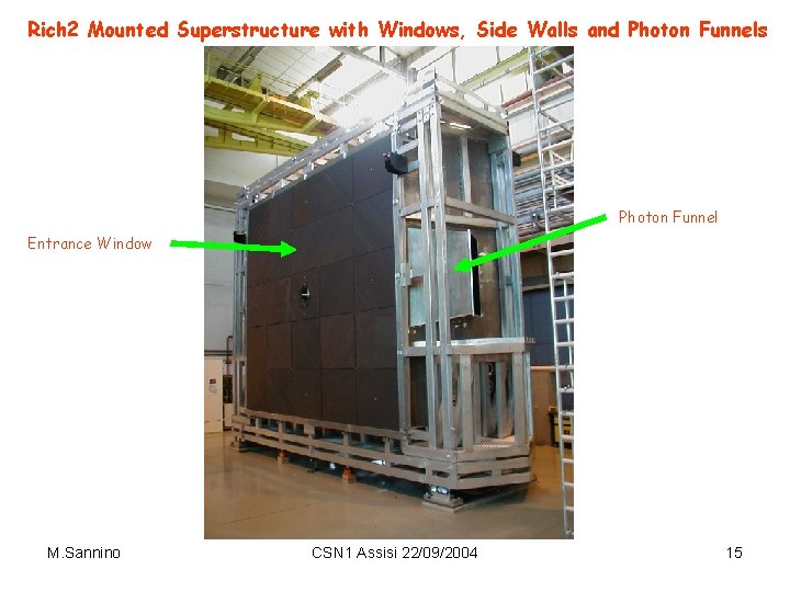
Rich 2 Mounted Superstructure with Windows, Side Walls and Photon Funnels Photon Funnel Entrance Window M. Sannino CSN 1 Assisi 22/09/2004 15
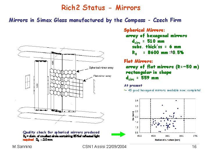
Rich 2 Status - Mirrors in Simax Glass manufactured by the Compass - Czech Firm Spherical Mirrors: array of hexagonal mirrors dcirc = 510 mm subs. thick’ss = 6 mm R 0 = 8600 mm 0. 5% Flat Mirrors: array of flat mirrors (R=~50 m) rectangular in shape dcirc = 559 mm At present • ~ 45 good hexagonal mirrors available now: complete! Quality check for spherical mirrors produced D 0 = diam. of smallest circle containing 95%of reflected light required D 0 2. 0 mm M. Sannino CSN 1 Assisi 22/09/2004 16
Rich 2 Status Photodetectors Housing • • • Photodetectors housing completely redesigned since Jan. 2004 due to much larger heat dissipation requirements than initially foreseen : each HPD plane 2 k. W instead than ~200 W foreseen in the EDR due to much larger dissipation both of pixel chip (~1. 8 W/chip) and associated L 0 electronics. To ease cooling electronics PCB’s (L 0, HV, LV) are arranged on the same plane differently from the old design, while the general frame design is retained with proper modifications in order to accommodate the electronic boards. In new design Cu cooling plates with active C 6 F 12 system in order to cool L 0 electronics. Precision positioning of HPD’s and cooling of pixel chips implemented by means of special mounting cup (spacer) together with cold fingers conducting heat to cooled frames where cooling plates are installed. HPD signal pinout inserted into a ZIF connector mounted on a special PCB (translator) in turn connected to L 0 electronics by means of a couple of Flexible (Kapton) Printed Circuits. Proper termination resistors are implemented on the translator PCB M. Sannino CSN 1 Assisi 22/09/2004 17
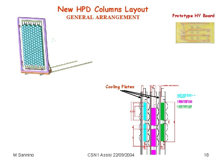
New HPD Columns Layout GENERAL ARRANGEMENT Prototype HV Board Cooling Plates M. Sannino CSN 1 Assisi 22/09/2004 18
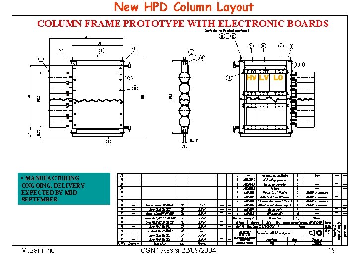
New HPD Column Layout COLUMN FRAME PROTOTYPE WITH ELECTRONIC BOARDS • MANUFACTURING ONGOING, DELIVERY EXPECTED BY MID SEPTEMBER M. Sannino CSN 1 Assisi 22/09/2004 19
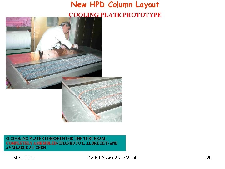
New HPD Column Layout COOLING PLATE PROTOTYPE • 3 COOLING PLATES FORESEEN FOR THE TEST BEAM COMPLETELY ASSEMBLED (THANKS TO E. ALBRECHT) AND AVAILABLE AT CERN M. Sannino CSN 1 Assisi 22/09/2004 20
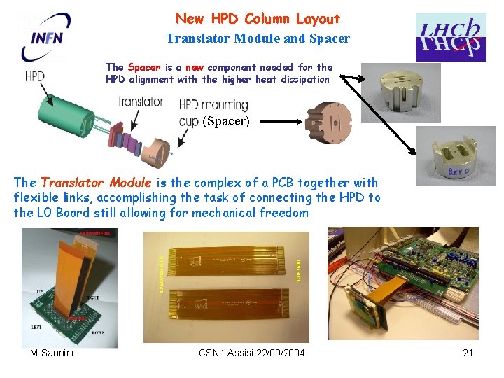
New HPD Column Layout Translator Module and Spacer The Spacer is a new component needed for the HPD alignment with the higher heat dissipation (Spacer) The Translator Module is the complex of a PCB together with flexible links, accomplishing the task of connecting the HPD to the L 0 Board still allowing for mechanical freedom M. Sannino CSN 1 Assisi 22/09/2004 21
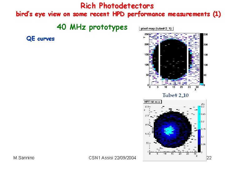
Rich Photodetectors bird’s eye view on some recent HPD performance measurements (1) 40 MHz prototypes QE curves M. Sannino CSN 1 Assisi 22/09/2004 22
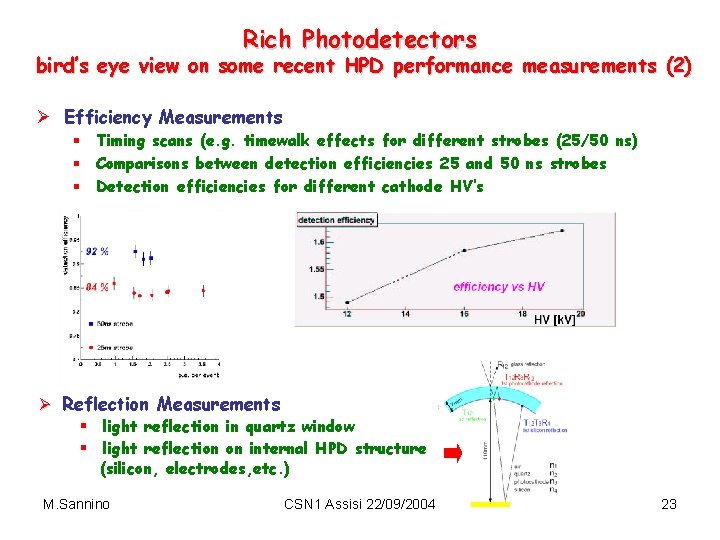
Rich Photodetectors bird’s eye view on some recent HPD performance measurements (2) Ø Efficiency Measurements § Timing scans (e. g. timewalk effects for different strobes (25/50 ns) § Comparisons between detection efficiencies 25 and 50 ns strobes § Detection efficiencies for different cathode HV’s Ø Reflection Measurements § light reflection in quartz window § light reflection on internal HPD structure (silicon, electrodes, etc. ) M. Sannino CSN 1 Assisi 22/09/2004 23
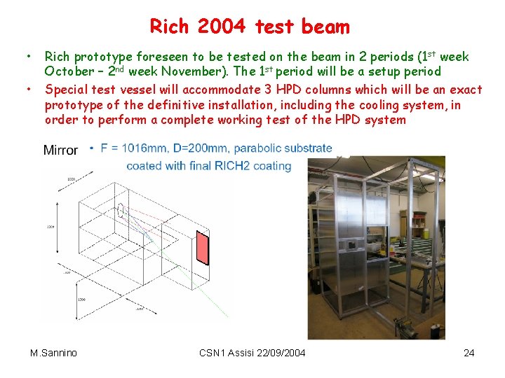
Rich 2004 test beam • • Rich prototype foreseen to be tested on the beam in 2 periods (1 st week October – 2 nd week November). The 1 st period will be a setup period Special test vessel will accommodate 3 HPD columns which will be an exact prototype of the definitive installation, including the cooling system, in order to perform a complete working test of the HPD system M. Sannino CSN 1 Assisi 22/09/2004 24
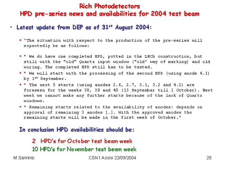
Rich Photodetectors HPD pre-series news and availabilities for 2004 test beam • Latest update from DEP as of 31 st August 2004: 2004 § “The situation with respect to the production of the pre-series will expectedly be as follows: § * We do have one completed HPD, potted in the LHCb construction, but still with the "old" Quartz input window ("old” way of marking) and old wiring. The completed HPD still has to be tested. § * We will start with the processing of the second HPD (using anode 4. 1) by 1 st September. § * The next 5 starts (using anodes 2. 6, 2. 7, 3. 1, 3. 2 and 4. 2) are foreseen for the weeks 38, 39 and 40 (13 September till 1 October). Next week we cannot make any further starts because of the lack of Quartz windows. § * Remaining starts related to the availability of anodes: depends on approval of remaining 3 anodes […]. With the approved anodes the remaining starts will be made in the first week of October. ” In conclusion HPD availabilities should be: 2 HPD’s for October test beam week 10 HPD’s for November test beam week M. Sannino CSN 1 Assisi 22/09/2004 25
Spare Slides M. Sannino CSN 1 Assisi 22/09/2004 26
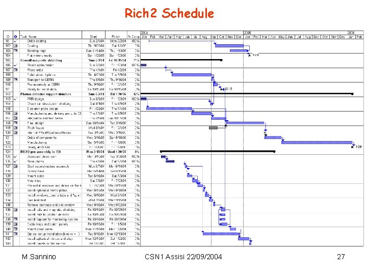
Rich 2 Schedule M. Sannino CSN 1 Assisi 22/09/2004 27
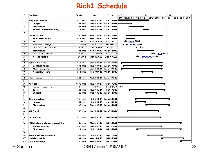
Rich 1 Schedule M. Sannino CSN 1 Assisi 22/09/2004 28
M. Sannino CSN 1 Assisi 22/09/2004 29
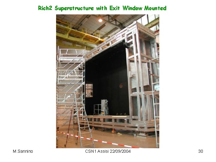
Rich 2 Superstructure with Exit Window Mounted M. Sannino CSN 1 Assisi 22/09/2004 30
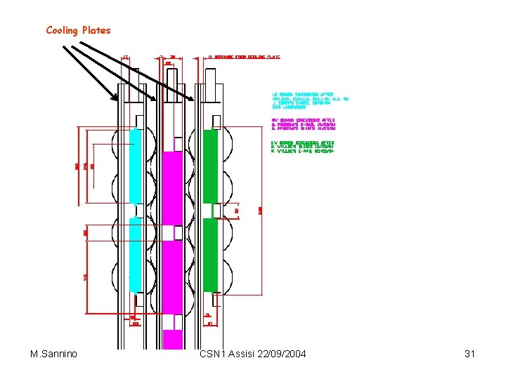
Cooling Plates M. Sannino CSN 1 Assisi 22/09/2004 31
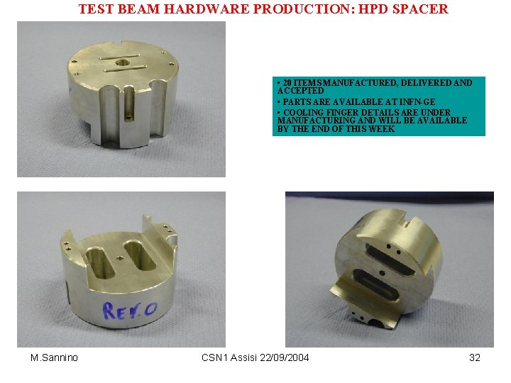
TEST BEAM HARDWARE PRODUCTION: HPD SPACER • 20 ITEMS MANUFACTURED, DELIVERED AND ACCEPTED • PARTS ARE AVAILABLE AT INFN-GE • COOLING FINGER DETAILS ARE UNDER MANUFACTURING AND WILL BE AVAILABLE BY THE END OF THIS WEEK M. Sannino CSN 1 Assisi 22/09/2004 32
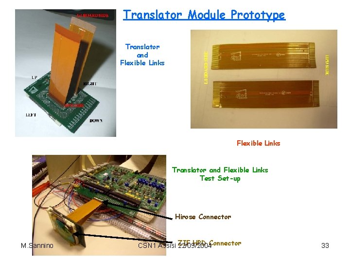
Translator Module Prototype Translator and Flexible Links Test Set-up Hirose Connector M. Sannino ZIF HPD Connector CSN 1 Assisi 22/09/2004 33
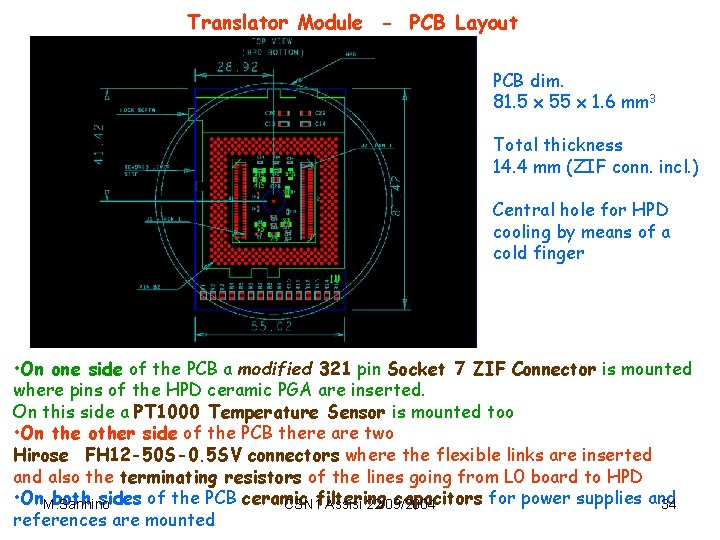
Translator Module - PCB Layout PCB dim. 81. 5 x 55 x 1. 6 mm 3 Total thickness 14. 4 mm (ZIF conn. incl. ) Central hole for HPD cooling by means of a cold finger • On one side of the PCB a modified 321 pin Socket 7 ZIF Connector is mounted where pins of the HPD ceramic PGA are inserted. On this side a PT 1000 Temperature Sensor is mounted too • On the other side of the PCB there are two Hirose FH 12 -50 S-0. 5 SV connectors where the flexible links are inserted and also the terminating resistors of the lines going from L 0 board to HPD • On. M. Sannino both sides of the PCB ceramic capacitors for power supplies and CSN 1 filtering Assisi 22/09/2004 34 references are mounted
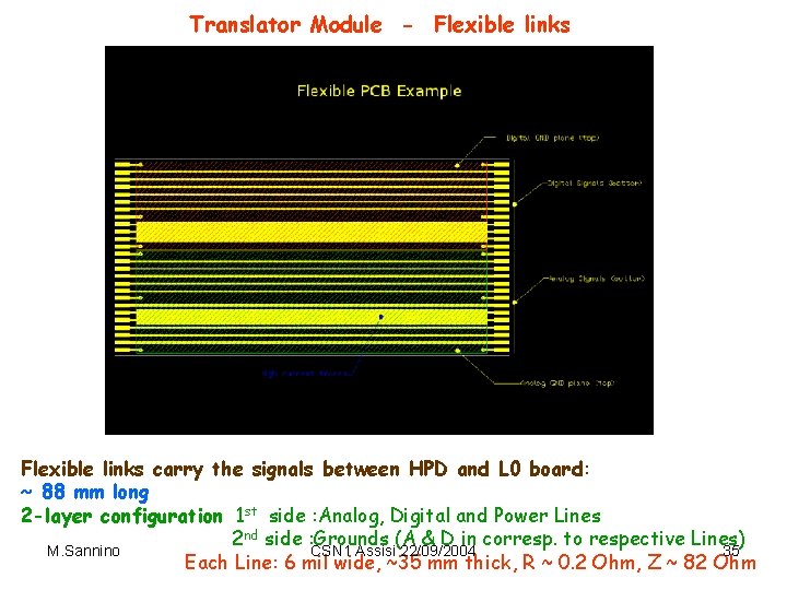
Translator Module - Flexible links carry the signals between HPD and L 0 board: ~ 88 mm long 2 -layer configuration 1 st side : Analog, Digital and Power Lines 2 nd side : Grounds (A & D in corresp. to respective Lines) M. Sannino CSN 1 Assisi 22/09/2004 35 Each Line: 6 mil wide, ~35 mm thick, R ~ 0. 2 Ohm, Z ~ 82 Ohm
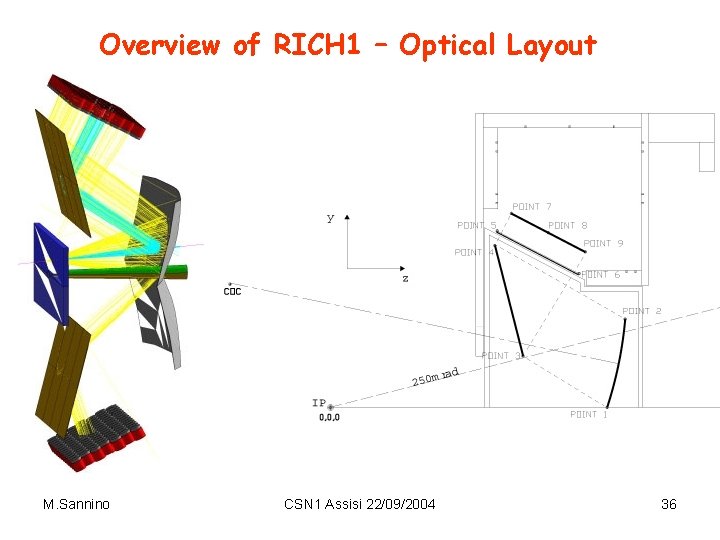
Overview of RICH 1 – Optical Layout M. Sannino CSN 1 Assisi 22/09/2004 36
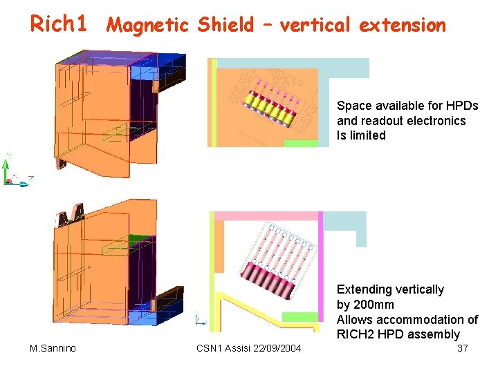
Rich 1 Magnetic Shield – vertical extension Space available for HPDs and readout electronics Is limited Extending vertically by 200 mm Allows accommodation of RICH 2 HPD assembly M. Sannino CSN 1 Assisi 22/09/2004 37
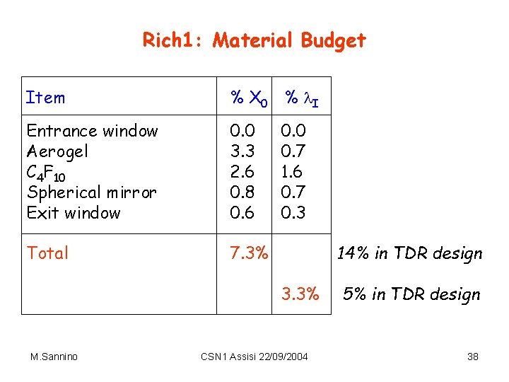
Rich 1: Material Budget Item % X 0 % l. I Entrance window Aerogel C 4 F 10 Spherical mirror Exit window 0. 0 3. 3 2. 6 0. 8 0. 6 Total 7. 3% 0. 0 0. 7 1. 6 0. 7 0. 3 14% in TDR design 3. 3% M. Sannino CSN 1 Assisi 22/09/2004 5% in TDR design 38
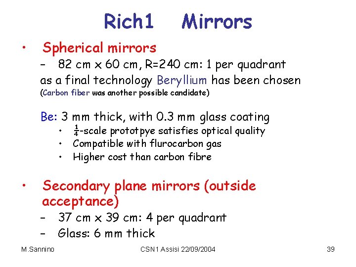
Rich 1 • Mirrors Spherical mirrors – 82 cm x 60 cm, R=240 cm: 1 per quadrant as a final technology Beryllium has been chosen (Carbon fiber was another possible candidate) Be: 3 mm thick, with 0. 3 mm glass coating • • ¼-scale prototpye satisfies optical quality Compatible with flurocarbon gas Higher cost than carbon fibre Secondary plane mirrors (outside acceptance) – – M. Sannino 37 cm x 39 cm: 4 per quadrant Glass: 6 mm thick CSN 1 Assisi 22/09/2004 39
HPD M. Sannino CSN 1 Assisi 22/09/2004 40
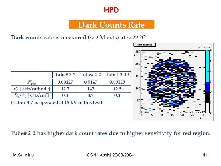
HPD M. Sannino CSN 1 Assisi 22/09/2004 41
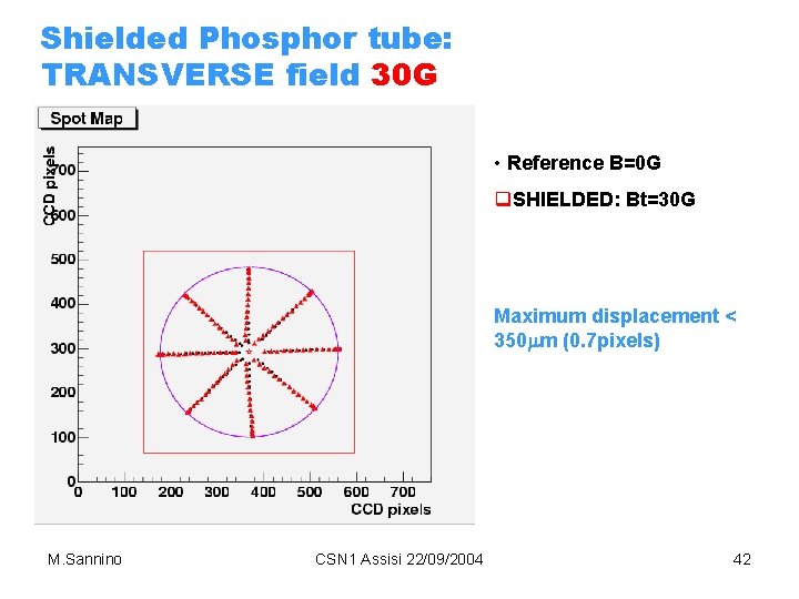
Shielded Phosphor tube: TRANSVERSE field 30 G • Reference B=0 G q. SHIELDED: Bt=30 G Maximum displacement < 350 mm (0. 7 pixels) M. Sannino CSN 1 Assisi 22/09/2004 42
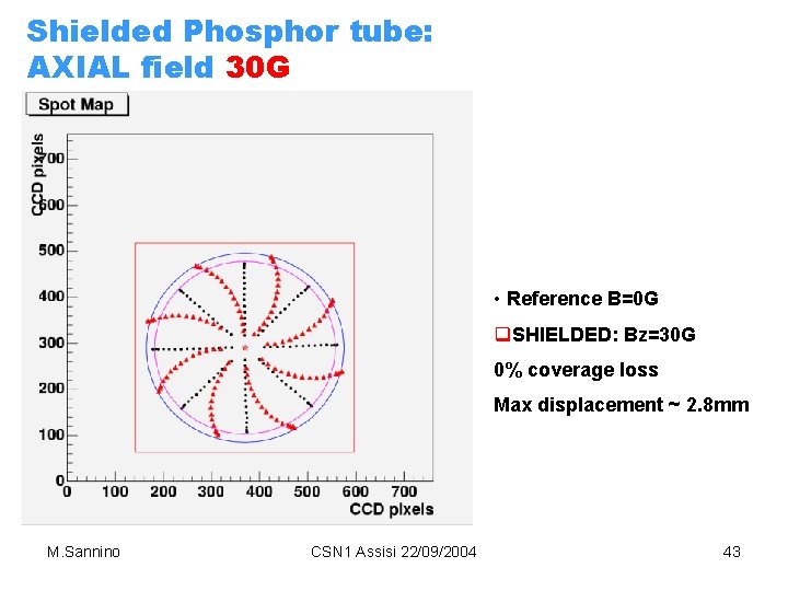
Shielded Phosphor tube: AXIAL field 30 G • Reference B=0 G q. SHIELDED: Bz=30 G 0% coverage loss Max displacement ~ 2. 8 mm M. Sannino CSN 1 Assisi 22/09/2004 43
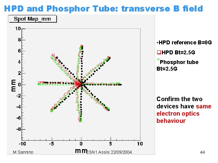
HPD and Phosphor Tube: transverse B field • HPD reference B=0 G q. HPD Bt=2. 5 G *Phosphor tube mm Bt=2. 5 G Confirm the two devices have same electron optics behaviour M. Sannino mm. CSN 1 Assisi 22/09/2004 44
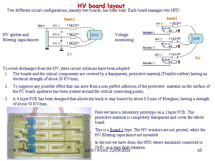
HV board layout Two different circuit configurations, namely two boards, has been built. Each board manages two HPD: HV splitter and filtering capacitances: Voltage monitoring: To avoid discharges from the HV, three circuit solutions have been adopted: 1. The boards and the critical components are covered by a transparent, protective material (Flexible rubber) having an electrical strength of about 20 KV/mm; 2. To suppress any possible effect that can arise from a non perfect adhesion of the protective material on the surface of the PC board, apertures has been created around the critical connecting points; 3. A 4 layer PCB has been designed that allows the track to stay buried by about 0. 8 mm of fiberglass, having a strength of about 50 KV/mm. Here we have a laboratory prototype on a 2 layer PCB. The protective material is completely transparent and cover the whole board. This is a Board 1 type. The HV resistors are not present, while the HV filtering capacitance are mounted. M. Sannino In the test we have done, the HPD where simulated connected to GND, as a very fault situation. CSN 1 Assisi 22/09/2004 45
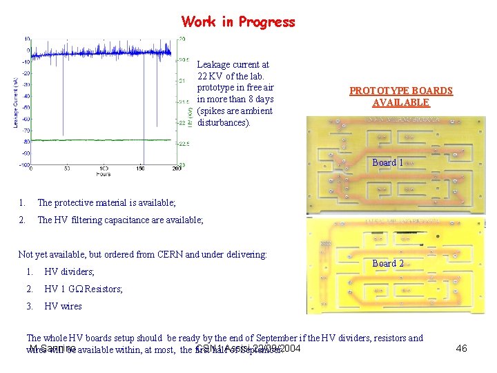
Work in Progress Leakage current at 22 KV of the lab. prototype in free air in more than 8 days (spikes are ambient disturbances). PROTOTYPE BOARDS AVAILABLE Board 1 1. The protective material is available; 2. The HV filtering capacitance are available; Not yet available, but ordered from CERN and under delivering: 1. HV dividers; 2. HV 1 G Resistors; 3. HV wires Board 2 The whole HV boards setup should be ready by the end of September if the HV dividers, resistors and M. Sannino CSN 1 22/09/2004 wires will be available within, at most, the first half. Assisi of September. 46
- Slides: 46