
Stato del Luminometro LUCID Outline The Lucid detector

- Slides: 49
Stato del Luminometro (LUCID) Outline: Ø The Lucid detector Ø Test beam results Ø Tests on Bench Ø The installation scenario Ø The electronics Ø Conclusions A. Bertin, M. Bruschi, D. Caforio, S. De Castro, L. Fabbri, P. Faccioli, B. Giacobbe, F. Grimaldi, I. Massa, M. Piccinini, M. Poli, C. Sbarra, ASbrizzi, N. Semprini-Cesari, R. Spighi, M. Villa, A. Vitale, A. Zoccoli May 16 th 2006 M. Bruschi – CSN 1 Roma 1
Activities of the Group since Sep. 05 Main activities of the Bologna Group in LUCID: Ø development of the electronics Ø Preparation (electronics, daq) Test Beam @ Desy (Nov. 05) and data analysis Ø Monte Carlo: development and optimization of the code (to reproduce the test beam results). Simulation of the backgrounds. Ø Test on bench @ CERN to check the detector performances and tune the MC Ø Discussion of the detector design and of the installation strategies May 16 th 2006 M. Bruschi – CSN 1 Roma 2
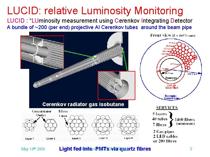
LUCID: relative Luminosity Monitoring LUCID : “LUminosity measurement using Cerenkov Integrating Detector A bundle of ~200 (per end) projective Al Cerenkov tubes around the beam pipe Cerenkov radiator gas isobutane May 16 th 2006 Bruschi – CSN 1 Light fed M. into PMTs via. Roma quartz fibres 3
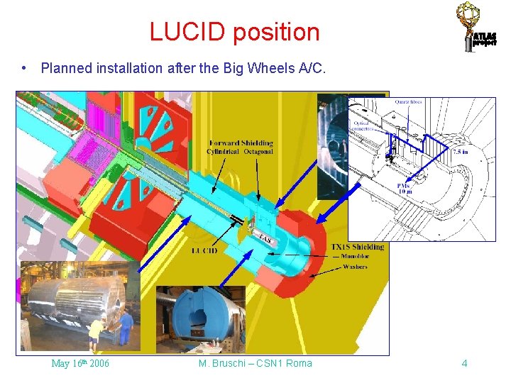
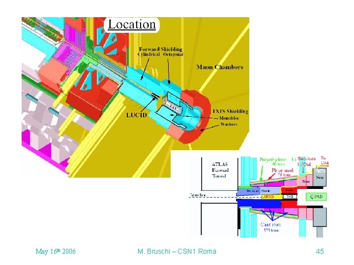
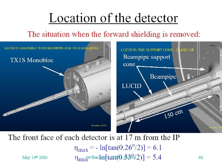
LUCID position • Planned installation after the Big Wheels A/C. May 16 th 2006 M. Bruschi – CSN 1 Roma 4
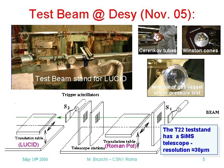
Test Beam @ Desy (Nov. 05): Test beam stand for Roman Pots Cerenkov tubes Winston cones Test Beam stand for LUCID window of gas vessel under pressure test (LUCID) May 16 th 2006 (Roman Pot) M. Bruschi – CSN 1 Roma The T 22 teststand has a Si. MS telescope resolution ≈30µm 5
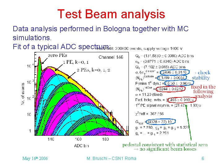
Test Beam analysis Data analysis performed in Bologna together with MC simulations. Fit of a typical ADC spectrum: May 16 th 2006 M. Bruschi – CSN 1 Roma 6
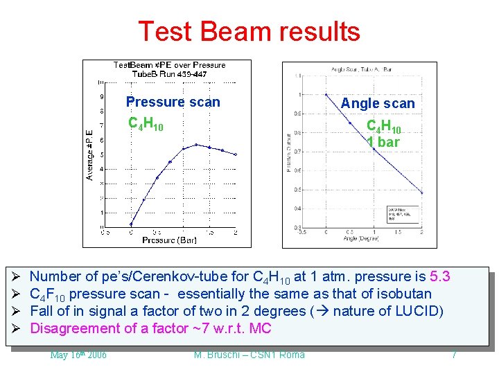
Test Beam results Pressure scan C 4 H 10 Ø Ø Angle scan C 4 H 10 1 bar Number of pe’s/Cerenkov-tube for C 4 H 10 at 1 atm. pressure is 5. 3 C 4 F 10 pressure scan - essentially the same as that of isobutan Fall of in signal a factor of two in 2 degrees ( nature of LUCID) Disagreement of a factor ~7 w. r. t. MC May 16 th 2006 M. Bruschi – CSN 1 Roma 7
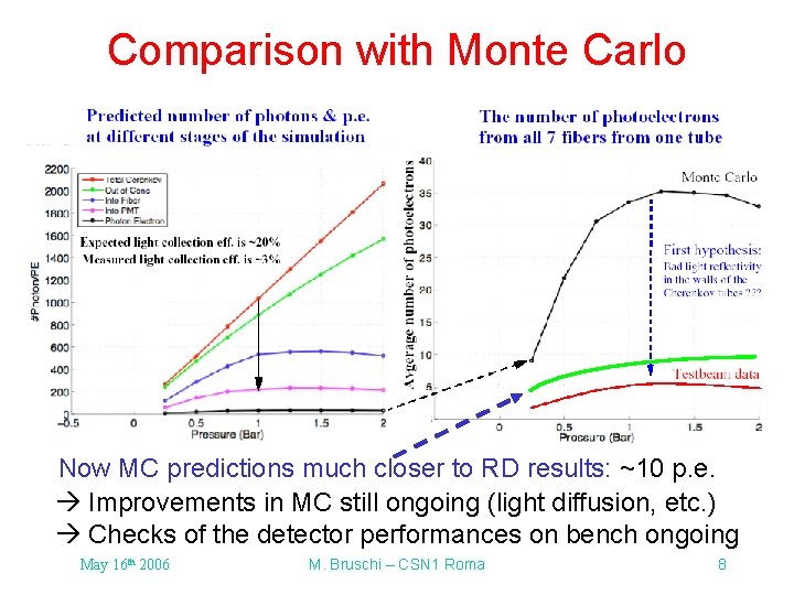
Comparison with Monte Carlo Stage A Now MC predictions much closer to RD results: ~10 p. e. Improvements in MC still ongoing (light diffusion, etc. ) Checks of the detector performances on bench ongoing May 16 th 2006 M. Bruschi – CSN 1 Roma 8
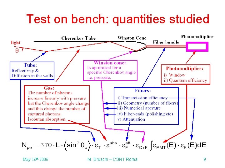
Test on bench: quantities studied May 16 th 2006 M. Bruschi – CSN 1 Roma 9
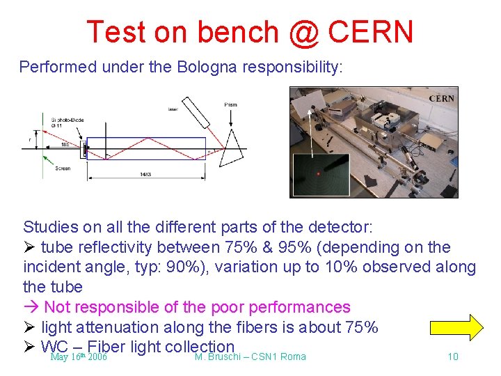
Test on bench @ CERN Performed under the Bologna responsibility: Studies on all the different parts of the detector: Ø tube reflectivity between 75% & 95% (depending on the incident angle, typ: 90%), variation up to 10% observed along the tube Not responsible of the poor performances Ø light attenuation along the fibers is about 75% Ø WC – Fiber light collection May 16 2006 M. Bruschi – CSN 1 Roma 10 th
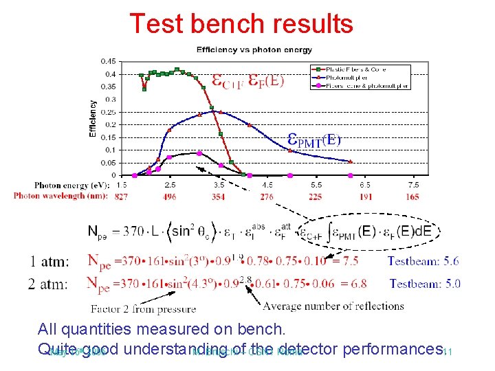
Test bench results All quantities measured on bench. Quite understanding of– CSN 1 the Roma detector performances. 11 May 16 good 2006 M. Bruschi th
Possible improvements & next steps Improvements on the detector; • Tubes: improvements in the internal surface (~ 1. 1 - 1. 2) • Winston cone: new design + internal surface (~ 1. 2 - 1. 7) • Fibers: improve fiber quality. ~2 less attenuation (at 300 nm), factor of ~2 large angular acceptance plus a larger (core)/(clad) area ratio (0. 78 compared to 0. 68) ( ~2) • PM + Fibre: enlarge the light spectrum sensitivity of PM +fibers (UV range) (~ 2) Possible improvements in light collection: factor ~6/7 Next steps: • New tubes + WC + fibers will be delivered @ CERN middle May Test on bench • Test beam @ CERN end of June to test the new detector • Test beam @ CERN in November to test the final detector May 16 th 2006 M. Bruschi – CSN 1 Roma 12
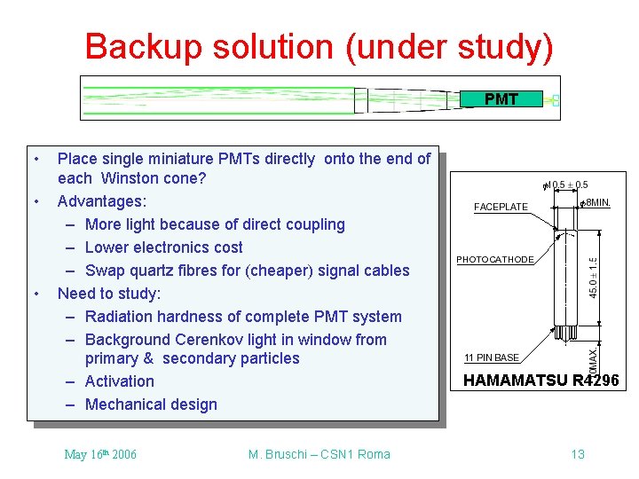
Backup solution (under study) PMT • • • Place single miniature PMTs directly onto the end of each Winston cone? Advantages: – More light because of direct coupling – Lower electronics cost – Swap quartz fibres for (cheaper) signal cables Need to study: – Radiation hardness of complete PMT system – Background Cerenkov light in window from primary & secondary particles – Activation – Mechanical design May 16 th 2006 M. Bruschi – CSN 1 Roma HAMAMATSU R 4296 13
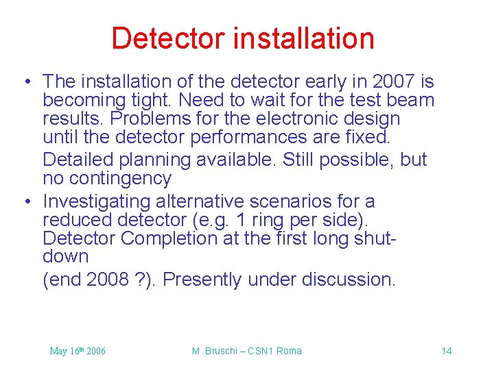
Detector installation • The installation of the detector early in 2007 is becoming tight. Need to wait for the test beam results. Problems for the electronic design until the detector performances are fixed. Detailed planning available. Still possible, but no contingency • Investigating alternative scenarios for a reduced detector (e. g. 1 ring per side). Detector Completion at the first long shutdown (end 2008 ? ). Presently under discussion. May 16 th 2006 M. Bruschi – CSN 1 Roma 14
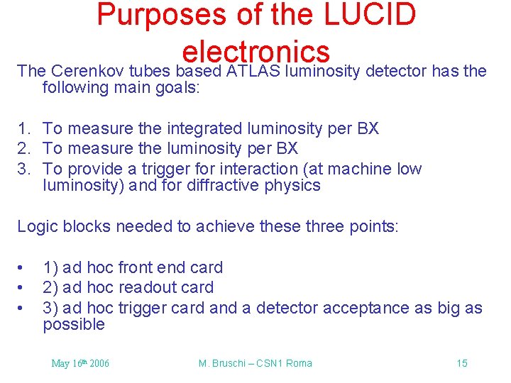
Purposes of the LUCID electronics The Cerenkov tubes based ATLAS luminosity detector has the following main goals: 1. To measure the integrated luminosity per BX 2. To measure the luminosity per BX 3. To provide a trigger for interaction (at machine low luminosity) and for diffractive physics Logic blocks needed to achieve these three points: • • • 1) ad hoc front end card 2) ad hoc readout card 3) ad hoc trigger card and a detector acceptance as big as possible May 16 th 2006 M. Bruschi – CSN 1 Roma 15
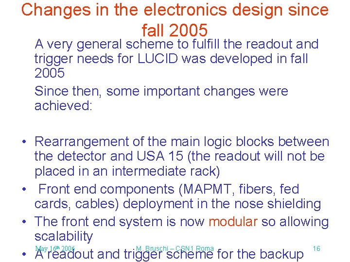
Changes in the electronics design since fall 2005 A very general scheme to fulfill the readout and trigger needs for LUCID was developed in fall 2005 Since then, some important changes were achieved: • Rearrangement of the main logic blocks between the detector and USA 15 (the readout will not be placed in an intermediate rack) • Front end components (MAPMT, fibers, fed cards, cables) deployment in the nose shielding • The front end system is now modular so allowing scalability May 16 2006 M. Bruschi – CSN 1 Roma 16 • A readout and trigger scheme for the backup th
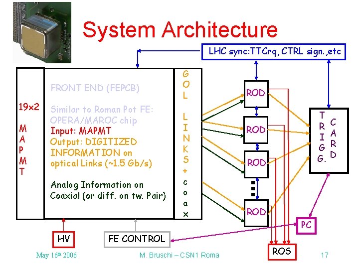
System Architecture LHC sync: TTCrq, CTRL sign. , etc FRONT END (FEPCB) 19 x 2 M A P M T Similar to Roman Pot FE: OPERA/MAROC chip Input: MAPMT Output: DIGITIZED INFORMATION on optical Links (~1. 5 Gb/s) Analog Information on Coaxial (or diff. on tw. Pair) HV May 16 th 2006 G O L L I N K S + c o a x ROD T R I G G. ROD ROD PC FE CONTROL M. Bruschi – CSN 1 Roma ROS 17 C A R D
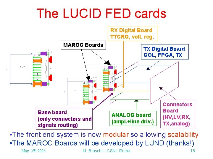
The LUCID FED cards RX Digital Board TTCRQ, volt. reg. MAROC Boards Base board (only connectors and signals routing) TX Digital Board GOL, FPGA, TX ANALOG board (ampl. +line driv. ) Connectors Board (HV, LV, RX, TX, analog) • The front end system is now modular so allowing scalability • The MAROC Boards will be developed by LUND (thanks!) May 16 th 2006 M. Bruschi – CSN 1 Roma 18
Conclusions/detector Ø LUCID can rely on quite settled technologies both on the detector & the electronics side Ø Detailed studies on the detector in test-beam and laser tests and a lot more is known (simulation, mechanics, light detection, fiber readout, cabling, electronics placement, readout, etc…). Good chances to improve the light emission by about a factor 6 -7. Ø Improved detector version will be tested in May on bench and in the test beam of June Ø Large impact of the Bologna Group on all the ongoing activities Ø Different installation scenarios under discussion. Aim for installation of LUCID in 2007. May 16 th 2006 M. Bruschi – CSN 1 Roma 19
Conclusions/electronics Ø The design of the front-end electronics has been started (although we need a confirmation of the performances of the detector) Ø The front end electronics (both for the baseline and the backup solution) should be reasonably ready for february 2007 Ø The project is now modular and can easily adapted in case we will decide for the LUCID readout backup solution Ø The development of the readout and trigger electronics could be a bit relaxed since we can use already available pieces of DAQ to give a luminosity measurement as soon as the front end electronics will be available ØMay First version of MAROC modifications for 16 2006 M. Bruschichip – CSN 1 including Roma 20 th LUCID submitted on March 6 th
Backup slides on detector May 16 th 2006 M. Bruschi – CSN 1 Roma 21
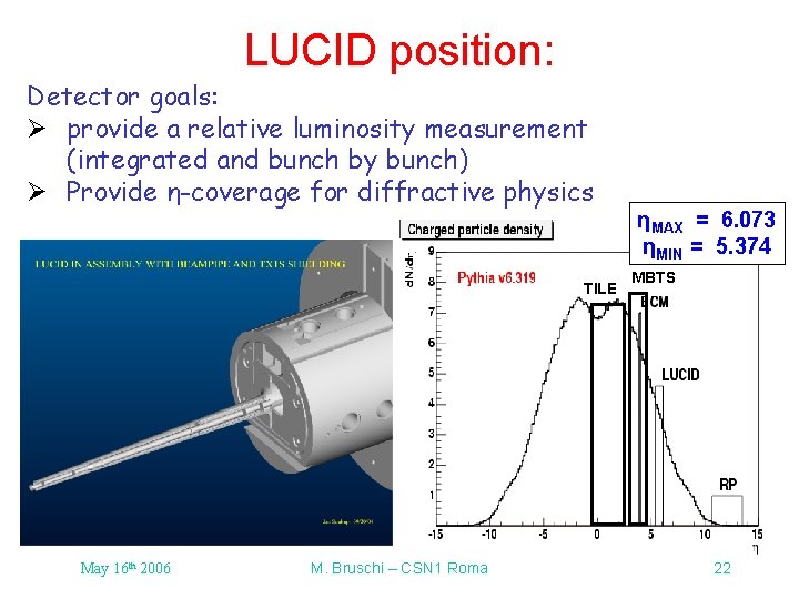
LUCID position: Detector goals: Ø provide a relative luminosity measurement (integrated and bunch by bunch) Ø Provide η-coverage for diffractive physics TILE May 16 th 2006 M. Bruschi – CSN 1 Roma ηMAX = 6. 073 ηMIN = 5. 374 MBTS 22
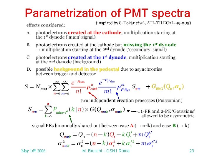
Parametrization of PMT spectra May 16 th 2006 M. Bruschi – CSN 1 Roma 23
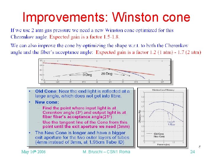
Improvements: Winston cone May 16 th 2006 M. Bruschi – CSN 1 Roma 24
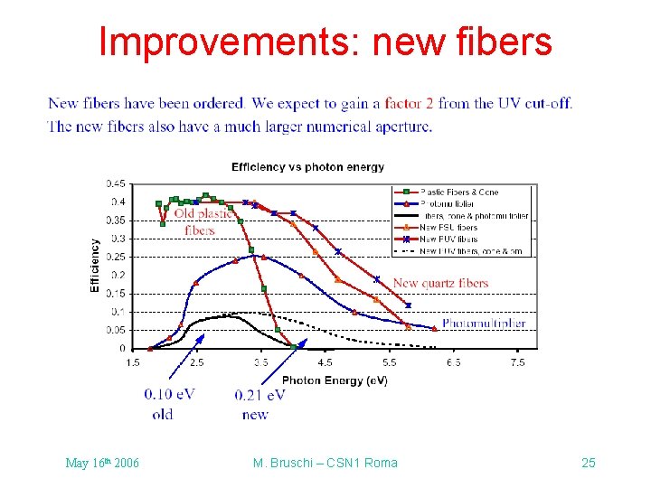
Improvements: new fibers May 16 th 2006 M. Bruschi – CSN 1 Roma 25
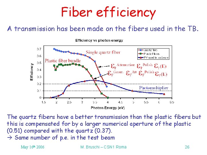
Fiber efficiency A transmission has been made on the fibers used in the TB. The quartz fibers have a better transmission than the plastic fibers but this is compensated for by a larger numerical aperture of the plastic (0. 51) compared with the quartz (0. 37). Same number of p. e. in the test beam May 16 th 2006 M. Bruschi – CSN 1 Roma 26
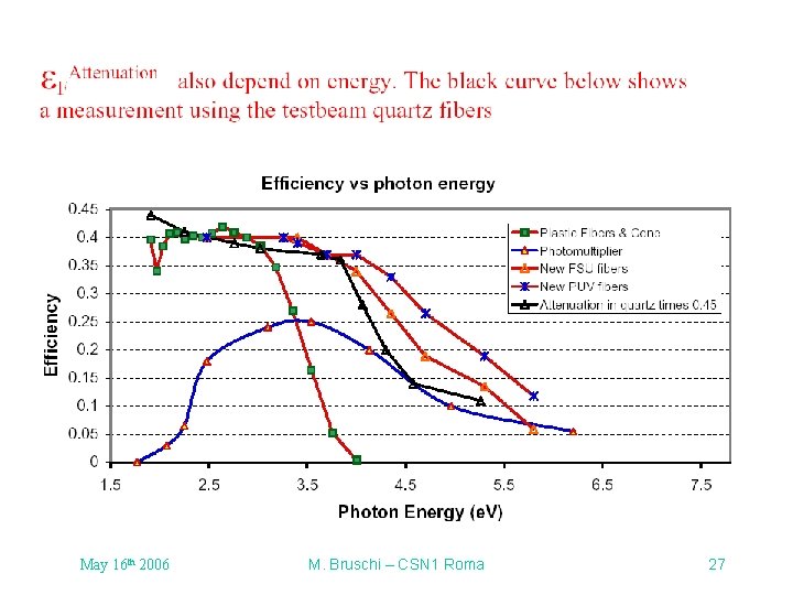
May 16 th 2006 M. Bruschi – CSN 1 Roma 27
BACKUP SLIDES on electronics May 16 th 2006 M. Bruschi – CSN 1 Roma 28
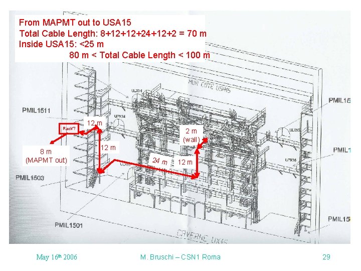
From MAPMT out to USA 15 Total Cable Length: 8+12+12+24+12+2 = 70 m Inside USA 15: <25 m 80 m < Total Cable Length < 100 m Rack? 8 m (MAPMT out) May 16 th 2006 12 m 2 m (wall) 12 m 24 m 12 m M. Bruschi – CSN 1 Roma 29
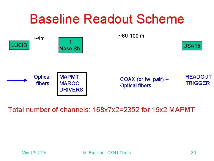
Baseline Readout Scheme ~4 m LUCID Optical fibers ~80 -100 m 1 Nose Sh. USA 15 MAPMT MAROC DRIVERS COAX (or tw. pair) + Optical fibers READOUT TRIGGER Total number of channels: 168 x 7 x 2=2352 for 19 x 2 MAPMT May 16 th 2006 M. Bruschi – CSN 1 Roma 30
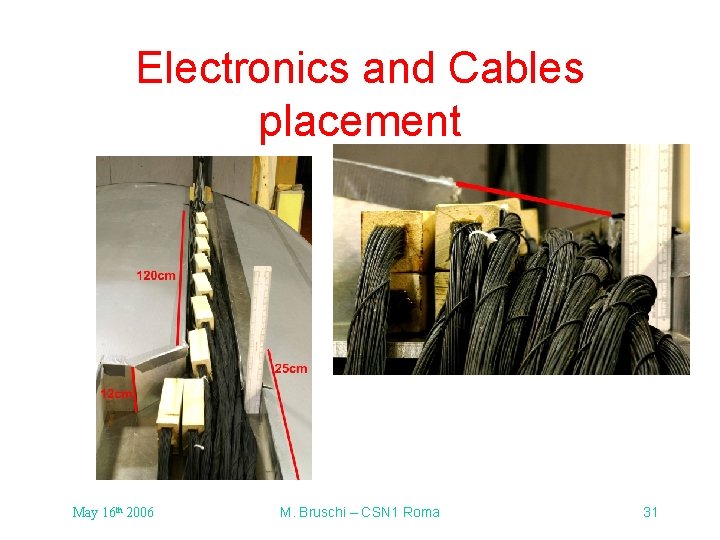
Electronics and Cables placement May 16 th 2006 M. Bruschi – CSN 1 Roma 31
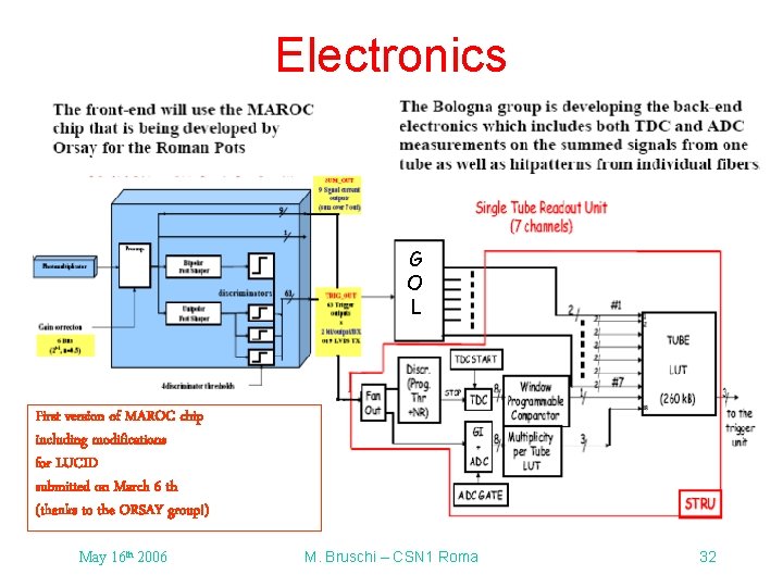
Electronics G O L First version of MAROC chip including modifications for LUCID submitted on March 6 th (thanks to the ORSAY group!) May 16 th 2006 M. Bruschi – CSN 1 Roma 32
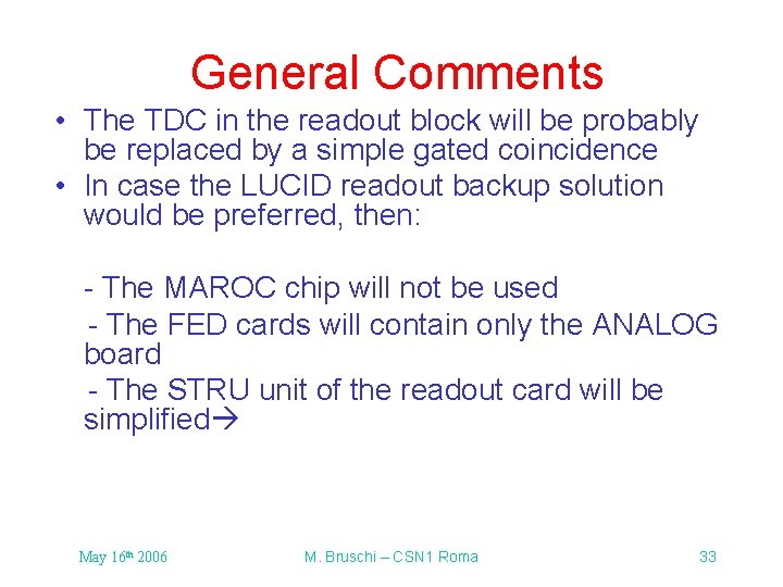
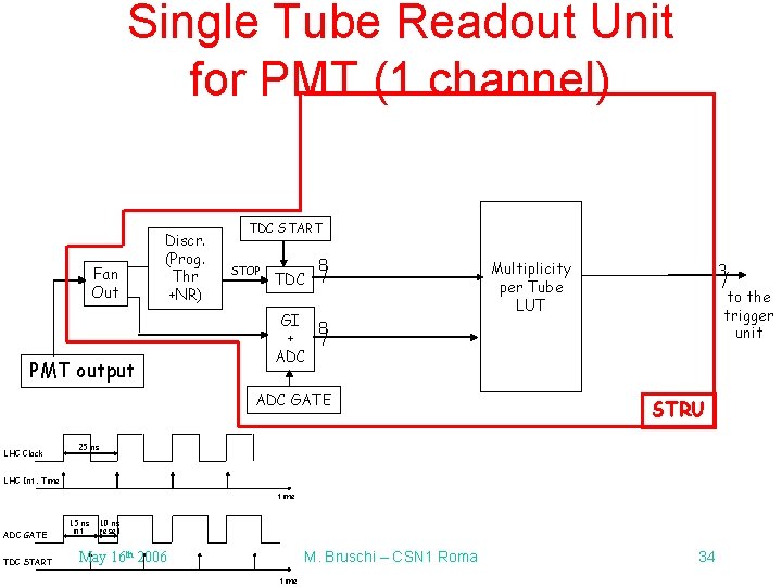
General Comments • The TDC in the readout block will be probably be replaced by a simple gated coincidence • In case the LUCID readout backup solution would be preferred, then: - The MAROC chip will not be used - The FED cards will contain only the ANALOG board - The STRU unit of the readout card will be simplified May 16 th 2006 M. Bruschi – CSN 1 Roma 33
Single Tube Readout Unit for PMT (1 channel) Fan Out Discr. (Prog. Thr +NR) PMT output TDC START STOP TDC 8 GI 8 + ADC GATE LHC Clock Multiplicity per Tube LUT 3 to the trigger unit STRU 25 ns LHC Int. Time time ADC GATE TDC START 15 ns int 10 ns reset M. Bruschi – CSN 1 Roma May 16 th 2006 time 34
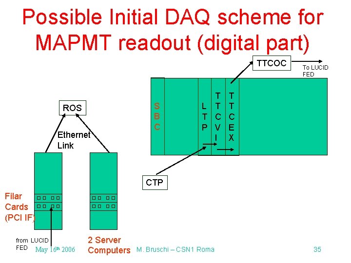
Possible Initial DAQ scheme for MAPMT readout (digital part) TTCOC ROS Ethernet Link S B C T L T T C P V I To LUCID FED T T C E X CTP Filar Cards (PCI IF) from LUCID FED May 16 th 2006 2 Server Computers M. Bruschi – CSN 1 Roma 35
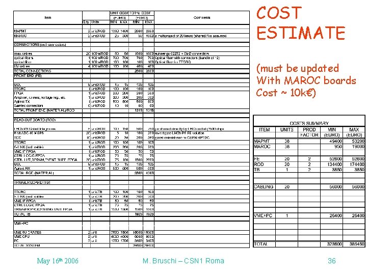
COST ESTIMATE (must be updated With MAROC boards Cost ~ 10 k€) May 16 th 2006 M. Bruschi – CSN 1 Roma 36
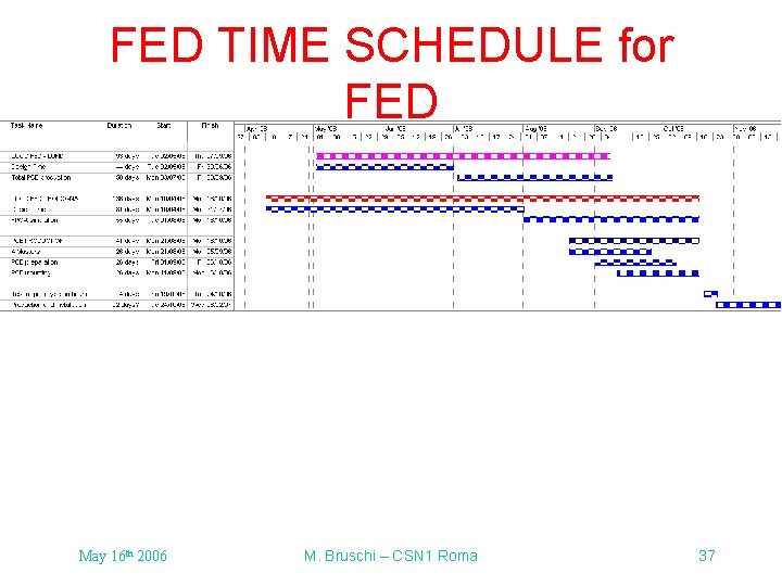
FED TIME SCHEDULE for FED May 16 th 2006 M. Bruschi – CSN 1 Roma 37
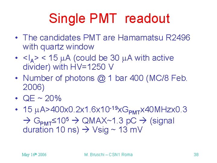
Single PMT readout • The candidates PMT are Hamamatsu R 2496 with quartz window • <IA> < 15 m. A (could be 30 m. A with active divider) with HV=1250 V • Number of photons @ 1 bar 400 (MC/8 Feb. 2006) • QE ~ 20% • 15 m. A>400 x 0. 2 x 1. 6 x 10 -19 x. GPMTx 40 MHzx 0. 3 GPMT≤ 105 QMAX~1. 3 p. C (signal duration 10 ns) Vsig ~ 13 m. V May 16 th 2006 M. Bruschi – CSN 1 Roma 38
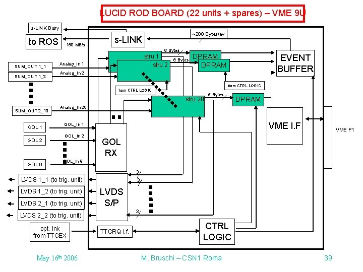
LUCID ROD BOARD (22 units + spares) – VME 9 U s-LINK Busy to ROS 160 MB/s ~200 Bytes/ev s-LINK 6 Bytes SUM_OUT 1_1 SUM_OUT 1_2 stru 1 stru 2 Analog_In 1 6 Bytes EVENT BUFFER DPRAM Analog_In 2 from CTRL LOGIC stru 20 SUM_OUT 2_10 GOL 1 GOL 2 GOL 9 6 Bytes DPRAM Analog_In 20 VME I. F GOL_In 1 GOL_In 2 VME P 1 GOL RX GOL_In 9 3 LVDS 1_1 (to trig. unit) LVDS 1_2 (to trig. unit) LVDS 2_1 (to trig. unit) 3 LVDS S/P 3 LVDS 2_2 (to trig. unit) opt. lnk from TTCEX May 16 th 2006 TTCRQ i. f. CTRL LOGIC M. Bruschi – CSN 1 Roma 39
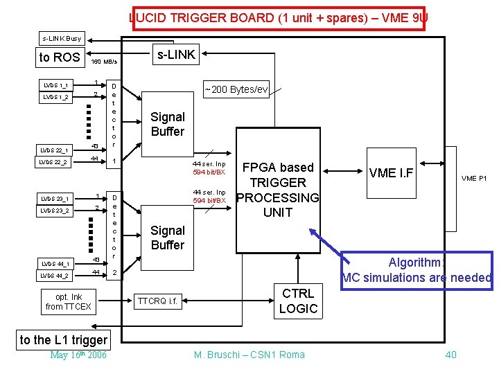
LUCID TRIGGER BOARD (1 unit + spares) – VME 9 U s-LINK Busy to ROS 160 MB/s 1 LVDS 1_1 43 D e t e c t o r 44 1 2 LVDS 1_2 LVDS 22_1 LVDS 22_2 LVDS 23_1 LVDS 23_2 LVDS 44_1 LVDS 44_2 1 43 D e t e c t o r 44 2 2 opt. lnk from TTCEX s-LINK ~200 Bytes/ev Signal Buffer 44 ser. Inp 594 bit/BX FPGA based TRIGGER PROCESSING UNIT VME I. F VME P 1 Signal Buffer Algorithm: MC simulations are needed TTCRQ i. f. CTRL LOGIC to the L 1 trigger May 16 th 2006 M. Bruschi – CSN 1 Roma 40
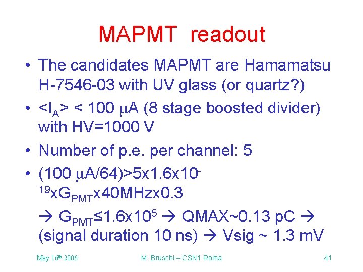
MAPMT readout • The candidates MAPMT are Hamamatsu H-7546 -03 with UV glass (or quartz? ) • <IA> < 100 m. A (8 stage boosted divider) with HV=1000 V • Number of p. e. per channel: 5 • (100 m. A/64)>5 x 1. 6 x 10¹⁹ x. G PMTx 40 MHzx 0. 3 GPMT≤ 1. 6 x 10⁵ QMAX~0. 13 p. C (signal duration 10 ns) Vsig ~ 1. 3 m. V May 16 th 2006 M. Bruschi – CSN 1 Roma 41
MAROC analog output characteristics • 25 m. V/160 f. C typical output from single fiber (130 f. C) ~ 20 m. V • Typical output from 7 fibers ~ 140 m. V May 16 th 2006 M. Bruschi – CSN 1 Roma 42
Cabling • The readout of the front includes both analog and digital signals transmission • For the analog ones: single ended on coaxial (but: differential on twisted pairs under consideration) • For the digital ones: optical fiber is the baseline May 16 th 2006 M. Bruschi – CSN 1 Roma 43
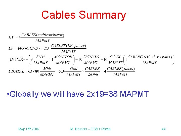
Cables Summary • Globally we will have 2 x 19=38 MAPMT May 16 th 2006 M. Bruschi – CSN 1 Roma 44
May 16 th 2006 M. Bruschi – CSN 1 Roma 45
May 16 th 2006 M. Bruschi – CSN 1 Roma 46
May 16 th 2006 M. Bruschi – CSN 1 Roma 47
May 16 th 2006 M. Bruschi – CSN 1 Roma 48
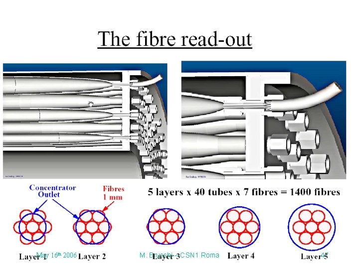
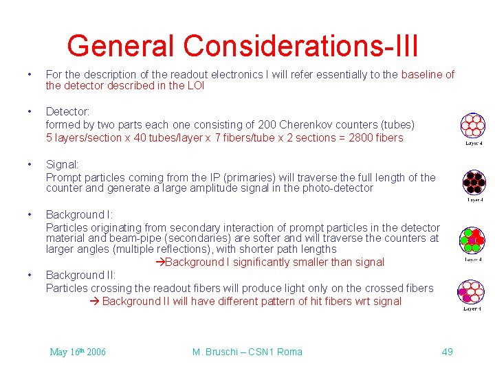
General Considerations-III • For the description of the readout electronics I will refer essentially to the baseline of the detector described in the LOI • Detector: formed by two parts each one consisting of 200 Cherenkov counters (tubes) 5 layers/section x 40 tubes/layer x 7 fibers/tube x 2 sections = 2800 fibers • Signal: Prompt particles coming from the IP (primaries) will traverse the full length of the counter and generate a large amplitude signal in the photo-detector • Background I: Particles originating from secondary interaction of prompt particles in the detector material and beam-pipe (secondaries) are softer and will traverse the counters at larger angles (multiple reflections), with shorter path lengths Background I significantly smaller than signal Background II: Particles crossing the readout fibers will produce light only on the crossed fibers Background II will have different pattern of hit fibers wrt signal • May 16 th 2006 M. Bruschi – CSN 1 Roma 49