State Machine Diagrams State Machine Diagrams State machine


 present an")


- Slides: 42
State Machine Diagrams
State Machine Diagrams • State machine diagram is a behavior diagram which shows discrete behavior of a part of designed system through finite state transitions. State machine diagrams can also be used to express the usage protocol of part of a system. • A statechart diagram shows the lifecycle of an object: what events it experiences, its transitions, and the states it is in between these events.
State Machine Diagrams Subject of a Statechart Diagram. A statechart diagram may be applied to a variety of UML elements, including: • classes (conceptual or software) • use cases
State Machine Diagrams • The following nodes and edges are typically drawn in state machine diagram: • behavioral state, • behavioral transition, • protocol state, • protocol transition, • different pseudostates.
Types of State Machine Diagrams • Behavioral State Machine • Protocol State Machine
Behavioral State Machine • Behavioral state machine is specialization of behavior and is used to specify discrete behavior of a part of designed system through finite state transitions. • Behavior is modeled as a traversal of a graph of state nodes connected with transitions.
State Machine Diagram
Vertex • Vertex is named element which is an abstraction of a node in a state machine graph. In general, it can be the source or destination of any number of transitions. • Subclasses of vertex are: • state • pseudostate • State is a vertex which models a situation during which some (usually implicit) invariant condition holds.
Behavioral State • State in behavioral state machines models a situation during which some (usually implicit) invariant condition holds. The invariant may represent a static situation such as an object waiting for some external event to occur. However, it can also model dynamic conditions such as the process of performing some behavior (i. e. , the model element under consideration enters the state when the behavior commences and leaves it as soon as the behavior is completed).
• • The UML defines the following kinds of states: simple state, composite state, submachine state.
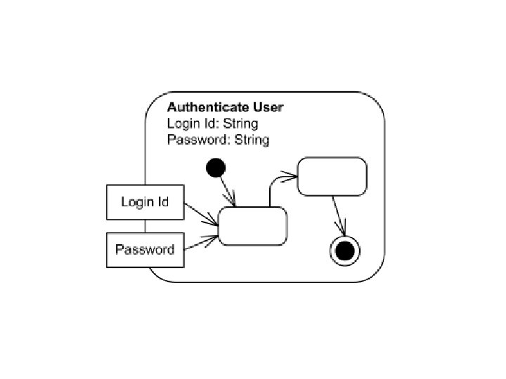
Simple State • A simple state is a state that does not have substates - it has no regions and it has no submachine states. • Simple state is shown as a rectangle with rounded corners and the state name inside the rectangle.
• Simple state may have compartments. The compartments of the state are: • name compartment • internal activities compartment • internal transitions compartment
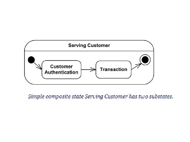
Composite State • Generally, composite state is defined as state that has substates (nested states). • Substates could be sequential (disjoint) or concurrent (orthogonal). • UML defines composite state as the state which contains one or more regions. (Note, that region is defined back as an orthogonal part of either a composite state or a state machine. ) A state is not allowed to have both regions and a submachine. • Simple composite state contains just one region.
Pseudostate • • • Pseudostates include: initial pseudostate terminate pseudostate entry point exit point choice join fork junction
• Initial Pseudostate-An initial pseudostate represents a default vertex that is the source for a single transition to the default state of a composite state
• Terminate Pseudostate- Terminate pseudostate implies that the execution of this state machine by means of its context object is terminated.
• Entry point pseudostate is • Exit point pseudostate is an an entry point of a state machine or composite state. In each region of the state machine or composite state it has at most a single transition to a vertex within the same region. exit point of a state machine or composite state. Entering an exit implies the exit of this composite state or submachine state and the triggering of the transition that has this exit point as source in the state machine enclosing the submachine or composite state.
• Choice
• Fork • Join Fork pseudostate vertices serve to split an incoming transition into two or more transitions Join pseudostate merges several transitions originating from source vertices in different orthogonal regions. The transitions entering a join vertex cannot have guards or triggers.
• Junction – Junction pseudostate vertices are vertices that are used to chain together multiple transitions. They are used to construct compound transition paths between states. • Final state is a special kind of state signifying that the enclosing region is completed.
Behavioral Transition • A transition is a directed relationship between a source vertex and a target vertex. transition : : =[ triggers ] [ guard ] [ '/' behavior-expression ] triggers : : = trigger [ ', ' trigger ]* guard : : = '[' constraint ']'
• Optional list of triggers specifies events that may induce state transition. • Since more than one transition may be enabled by the same event, it is a necessary but not sufficient condition for the firing of a transition. • The guard-constraint is a Boolean expression written in terms of parameters of the triggering event and attributes and links of the context object. • The behavior-expression is executed if and when the transition fires.
UML Protocol State Machine Diagrams
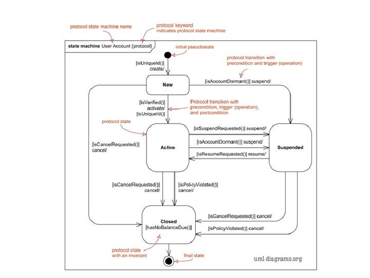
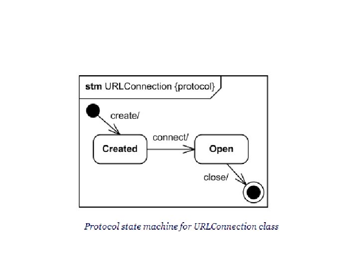
UML Protocol State Machine Diagrams • UML protocol state machine diagrams are used to express a usage protocol or a lifecycle of some classifier. • It shows which operations of the classifier may be called in each state of the classifier, under which specific conditions, and satisfying some optional postconditions after the classifier transitions to a target state.
UML Protocol State Machine Diagrams • Because these diagrams show lifecycle, they are useful to show different stable states of a class of objects which could exist for some time, and to explain how objects could change their states over the time. • For example, we can show User Account could be created, activated, suspended, and cancelled.
• Major elements of the protocol state machine diagram are • protocol state, • protocol transition, • different pseudostates
Protocol State • The states of a protocol state machine (protocol states) present an external view of the class that is exposed to its clients.
Protocol Transition
Activity Diagram
Activity Diagram • Activity diagram is UML behavior diagram which shows flow of control or object flow with emphasis on the sequence and conditions of the flow.
Activity Diagram • The following nodes and edges are typically drawn on UML activity diagrams: • activity, • partition, • action, • object, • control, • activity edge.
• Activity – Activity is a parameterized behavior represented as coordinated flow of actions. – The flow of execution is modeled as activity nodes connected by activity edges. A node can be the execution of a subordinate behavior, such as an arithmetic computation, a call to an operation, or manipulation of object contents.
• Activity contains activity nodes which could be: • action • object • control
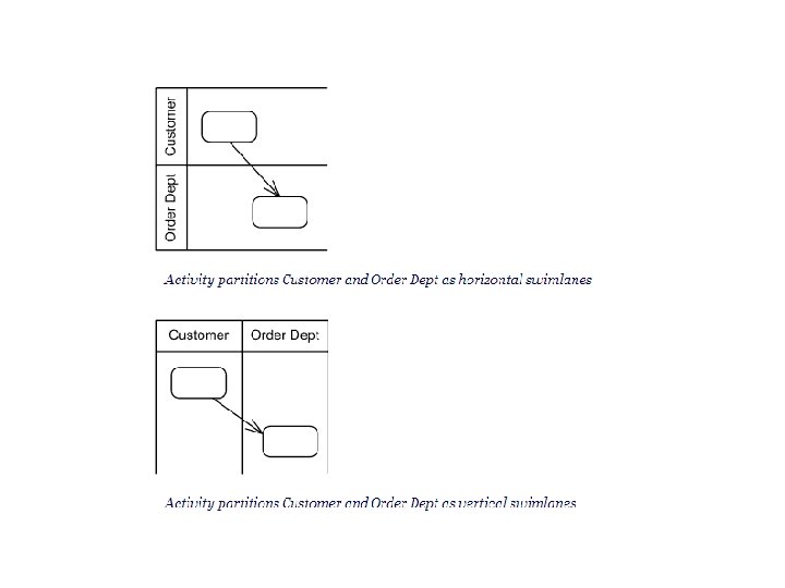
• Activity Partition – An activity partition is activity group for actions that have some common characteristic.
• Activity Edge • Edge with guard condition