Starting Systems Maintenance and Service Introduction Electrical systems


 • Technical Service Bulletins, or TSBs, are recommended procedures for repairing")


 • The number of vehicles equipped")


- Slides: 33
Starting Systems Maintenance and Service
Introduction • Electrical systems, such as ignition, charging, starting, lighting, and computer systems perform needed functions for a vehicle • Electrical system repair is an essential aspect of repairing a collisiondamaged vehicle • IC engines in the vehicles need separate systems for starting. • Starting resistances which must be overcome 1 - the press. inside cylinders(compression) 2 -inertia forces 3 -oil viscosity specially in cold engine 4 - friction between engine components(bearings)
Proper vehicle diagnosis requires a plan before you start Following a set procedure to base your troubleshooting on will help you find the root cause of a problem and prevent unnecessary repeat repairs STEP 1: Understand the Customer’s Concern Information collection beyond the basics. Questions asked MUST be related To the system you will be working on and the customer complaint STEP 2: Check for Technical Service Bulletins Every vehicle that comes into the shop for a repair (not necessary for routine maintenance) should be checked for TSB’s , This can save you hours of troubleshooting. STEP 3: Conduct a Systematic Diagnosis This step will be different for every system Follow the troubleshooting steps for the system you are working on. Make sure to check EVERY component of the system and that they are in proper working order. Document your diagnosis including tests and results. STEP 4: Complete and Confirm the Repair Make sure you have taken care of the customers concerns. Try to duplicate the conditions that were present when the vehicle failed
Technical Service Bulletins(TSB’s) • Technical Service Bulletins, or TSBs, are recommended procedures for repairing vehicles. • They are a form of diagnosis. Not to be confused with recalls, a TSB is issued by a vehicle manufacturer when there are several occurrences of an unanticipated problem.
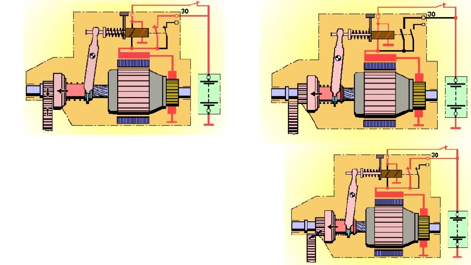
Starting System Troubleshooting A starter is a device that initiates engine operation. Since a vehicle engine cannot start unaided, an external force is required to provide rotational speed at or above a set value. The starter drives a built-in motor using the vehicle battery as a power source to create power and start the engine. Unlike normal DC motors, the starter is only used for a short time (rated at 30 seconds). Thus, the starter is designed to be very small despite producing a large output.
Starter components
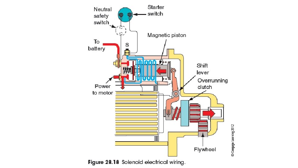
Starting System Components 1. 2. 3. 4. 5. 6. 7. 8. 9. Battery Ignition/Starter Switch (Electro-magnetic Switch (solenoid) or Relay Starting (cranking) Motor Safety Switch Pinion Gear Flywheel Ring Gear High-current Motor Circuit Cables Low-current Control Circuit wiring
Starter motor Brushes 10
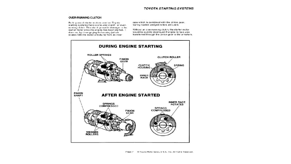
Starter Drives • Have an overrunning, or one-way clutch • Transmits motion from starter to flywheel • Disengages from the engine at startup • Teeth on the starter drive gear are tapered
12
A starter assembly engaging with a flywheel ring gear Gear Ratio 1: 15
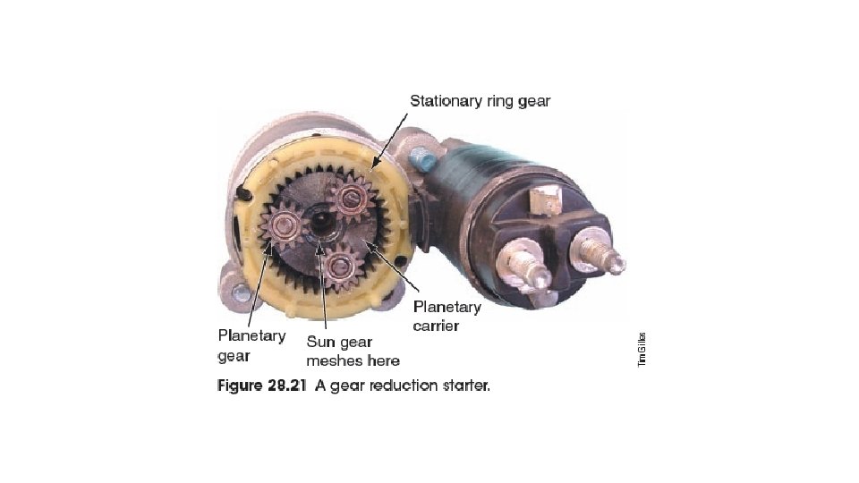
Gear Reduction Starters • Some manufacturers use gear reduction starters • Lighter • Use less current • Small in size • Lower gear ratio gives them enough torque • Smaller battery cables can also be used
Stop & Start Technology -Idling stop system (ISS) • The number of vehicles equipped with idling stop system (ISS) is on the rise due to increased public awareness of environmental issues, and stricter CO 2 exhaust gas regulations. The ISS automatically stops the engine* when the vehicle is not moving, and restarts the engine when accelerator depression is detected. Therefore, the amount of engine idle time decreases, and both the fuel consumption and CO 2 exhaust gas quantities are reduced by approximately 3 to 7 percent. • However, the ISS frequently operates the starter, leading to engine vibration and noise. To reduce these undesirable effects, a starting mechanism was required that could quickly and smoothly start and stop the engine. *Several conditions must be met to stop the engine. These conditions vary according to the vehicle
Example of ISS Operating Conditions Example Operating Conditions (Idling stop occurs when all of the following conditions are satisfied): • Engine Coolant Temperature : After Warm-Up • Driver-Side Door : Closed • Engine Hood : Closed • Road Surface Gradient: Approximately 10° or less • Vehicle Speed : 0 km/h • Accelerator Pedal: Released • Brake Pedal : Pressed • Shift Position : “D” range • Vehicle Speeds History : After and engine start-up and when speed is input • Idling Stop Button: ON
Starting System Troubleshooting Chart Symptom Possible Cause Corrective Action Engine will not crank Dead battery Check battery state of charge. Recharge if possible. Replace if necessary Melted fusible link Replace fusible link Loose connections Clean and tighten connections Key switch or start switch contacts in poor condition Replace switch as necessary Solenoid hold-in coil open. Pull-in coil open or shorted. Replace starter Solenoid contacts worn away Mechanical problem in engine Replace starter Check engine
Starting System Troubleshooting Chart Symptom Possible Cause Corrective Action Engine cranks too slowly to start Weak battery Check battery. Recharge if possible. Replace if necessary Loose or corroded connections Clean and tighten connections Faulty starter Starter spins, but engine will not crank Test starter, Replace if necessary Faulty over-running clutch Check over-running clutch, replace starter if necessary Damaged or worn starter pinion gear or engine ring gear. Check gears for damage or wear. Replace starter or ring gear
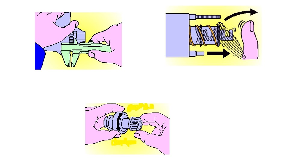
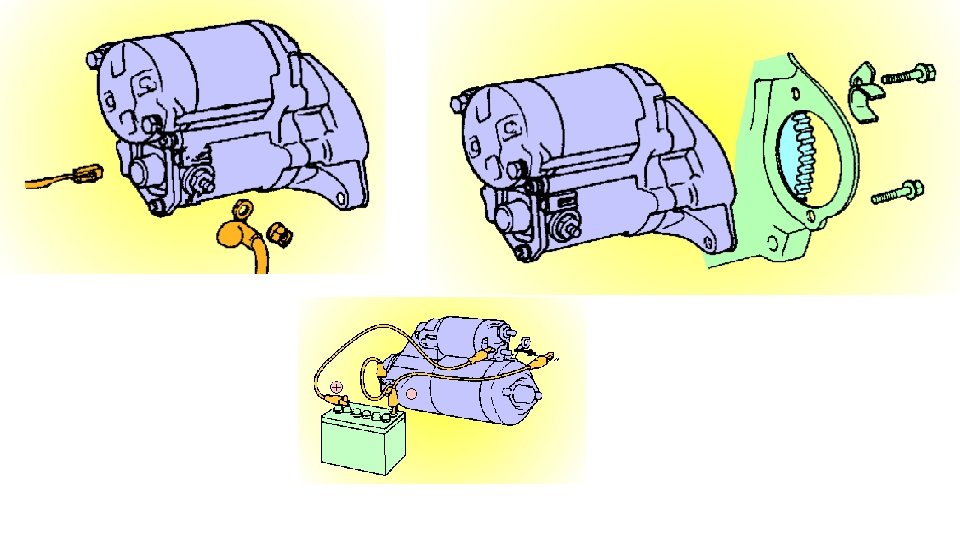
Starting System inspection check list Begin with a thorough visual inspection of system and components System tests: Battery Load test Confirm charging system operation System cables & wires Make sure all connections are clean and tight Check wires for fraying, insulation damage, and other physical damage Voltage drop test Check voltage drop on the complete circuit If problem is detected check positive side and negative side separately to isolate problem Check voltage at “KS” terminal on starter with ignition switch in the start position
Diagnostic Equipment • Locating an electrical fault is not possible without using diagnostic tools • A multimeter (VOM) is a voltmeter, ohmmeter, and ammeter combined into one case • A digital multimeter (DVOM) has a number readout for the test value • An analog multimeter (AVOM) has a pointer that moves across the face of a scale • Use of an AVOM can damage sensitive electronic components
Test Light, Jumper Wires • Test light can determine if current is flowing through a circuit • Jumper wires are used to temporarily bypass circuits or components for testing
Figure 26– 4. Jumper wires can be used to bypass resistive parts or to connect power directly to parts to check their operation. For example, if a motor runs when connected directly to voltage, you would know the circuit might not be providing power or a ground to the motor.
System voltage drop test
Positive side voltage drop test Test can be performed with: Electronic tester Carbon pile load tester Cranking engine (If cranking engine) 1) Disable the fuel or ignition system to keep the engine from starting during the test 2) DO NOT crank the engine for longer than 10 seconds at a time 3) Wait a minimum of 60 seconds before cranking engine again to cool the starter
Ground side voltage drop test Test can be performed with: Electronic tester Carbon pile load tester Cranking engine (If cranking engine) 1) Disable the fuel or ignition system to keep the engine from starting during the test 2) DO NOT crank the engine for longer than 10 seconds at a time 3) Wait a minimum of 60 seconds before cranking engine again to cool the starter
Commutator tests
Brushes tests