
Standalone Wind Energy Utilization Scheme and Novel Control
- Slides: 119
Standalone Wind Energy Utilization Scheme and Novel Control Strategies Prof. Dr. A. M. Sharaf
Outline ¡ Introduction ¡ Stand-alone WECS with Dynamic Series Switched Capacitor Scheme ¡ Stand-alone WECS with Dynamic Series/Parallel Compensation Scheme ¡ Stand-alone WECS with Dynamic Hybrid Power Compensation Scheme ¡ Stand-alone WECS with Dual-switching Universal Power Compensation 1 Scheme
Outline ¡ Stand-alone WECS with Universal DC-Link Compensation Scheme ¡ Wind-Diesel Standalone Energy System Using Dual-switching Universal Power Compensation 2 Scheme ¡ Conclusions and Recommendations ¡ Models ¡ Publications
1. Introduction 1. 1 Wind Energy ¡ ¡ Wind energy: one of the most significant, alternative energy resources. Most wind turbines use three phase asynchronous induction generator for it is low lost, reliable and less maintenance. However, the voltage stability problem of a wind driven induction generator system is fully dependent on wind gusting conditions and electrical load changes. New interface technologies are needed
1. Introduction 1. 2 Wind Energy Conversion Schemes Six novel techniques and compensation ¡ ¡ ¡ schemes developed by Dr. Sharaf in this thesis are proposed. Dynamic Series Switched Capacitor (DSSC) Dynamic Series/Parallel Capacitor (DSPC) Dynamic Hybrid Power Compensation (DHPC) Dynamic Dual-switching Universal Power Compensation 1 and 2 (DUPC 1&2) Universal DC-Link Compensation (UDCC)
1. Introduction 1. 2 Wind Energy Conversion Schemes ¡ ¡ ¡ ¡ Six PWM switched controllers developed by Dr. Sharaf are studied in this thesis. Aux controller. Tri-loop (voltage, current and power signals) error driven PID controller. Dual-loop (voltage and current) error driven PID controller. Tri-loop nonlinear self-adjusting Tansigmoid controller Voltage regulator controller. Tri-loop error driven sliding mode controller.
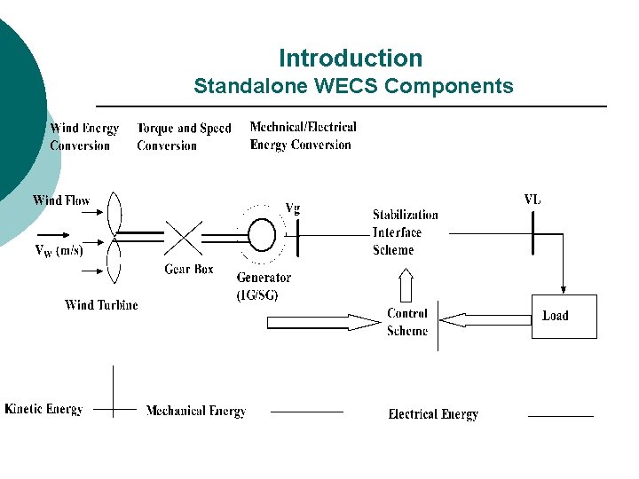
1. Introduction 1. 3 Standalone WECS Components ¡ ¡ ¡ The Stand-alone WECS comprises the following main components (1) Wind Turbine (2) Gear Box (3) Induction or Synchronous Generator (see the appendix A. 2 for generator models) (4) Stabilization Interface Scheme and Stabilization Controller (5) The Electric Load
Introduction Standalone WECS Components
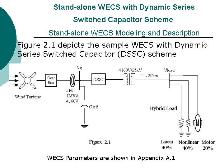
Stand-alone WECS with Dynamic Series Switched Capacitor Scheme Stand-alone WECS Modeling and Description Figure 2. 1 depicts the sample WECS with Dynamic Series Switched Capacitor (DSSC) scheme WECS Parameters are shown in Appendix A. 1
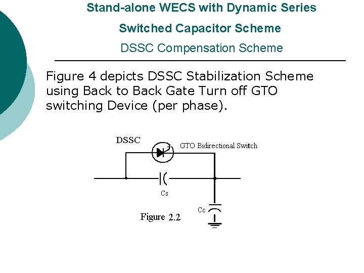
Stand-alone WECS with Dynamic Series Switched Capacitor Scheme DSSC Compensation Scheme Figure 4 depicts DSSC Stabilization Scheme using Back to Back Gate Turn off GTO switching Device (per phase).
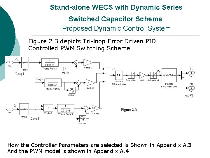
Stand-alone WECS with Dynamic Series Switched Capacitor Scheme Proposed Dynamic Control System Figure 2. 3 depicts Tri-loop Error Driven PID Controlled PWM Switching Scheme How the Controller Parameters are selected is Shown in Appendix A. 3 And the PWM model is shown in Appendix A. 4
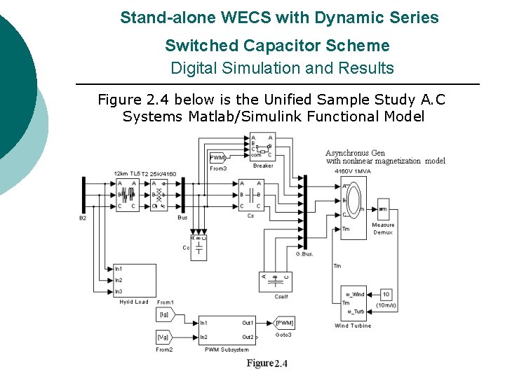
Stand-alone WECS with Dynamic Series Switched Capacitor Scheme Digital Simulation and Results Figure 2. 4 below is the Unified Sample Study A. C Systems Matlab/Simulink Functional Model
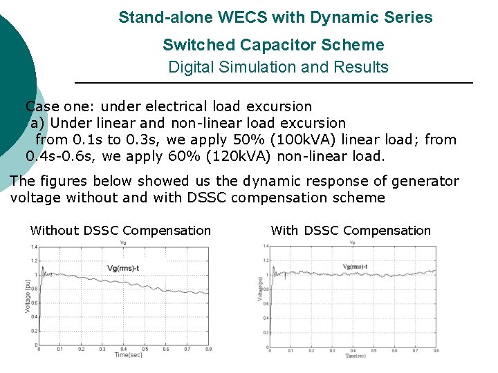
Stand-alone WECS with Dynamic Series Switched Capacitor Scheme Digital Simulation and Results Case one: under electrical load excursion a) Under linear and non-linear load excursion from 0. 1 s to 0. 3 s, we apply 50% (100 k. VA) linear load; from 0. 4 s-0. 6 s, we apply 60% (120 k. VA) non-linear load. The figures below showed us the dynamic response of generator voltage without and with DSSC compensation scheme Without DSSC Compensation With DSSC Compensation
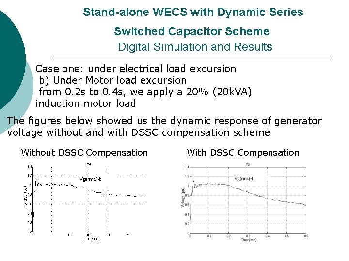
Stand-alone WECS with Dynamic Series Switched Capacitor Scheme Digital Simulation and Results Case one: under electrical load excursion b) Under Motor load excursion from 0. 2 s to 0. 4 s, we apply a 20% (20 k. VA) induction motor load The figures below showed us the dynamic response of generator voltage without and with DSSC compensation scheme Without DSSC Compensation With DSSC Compensation
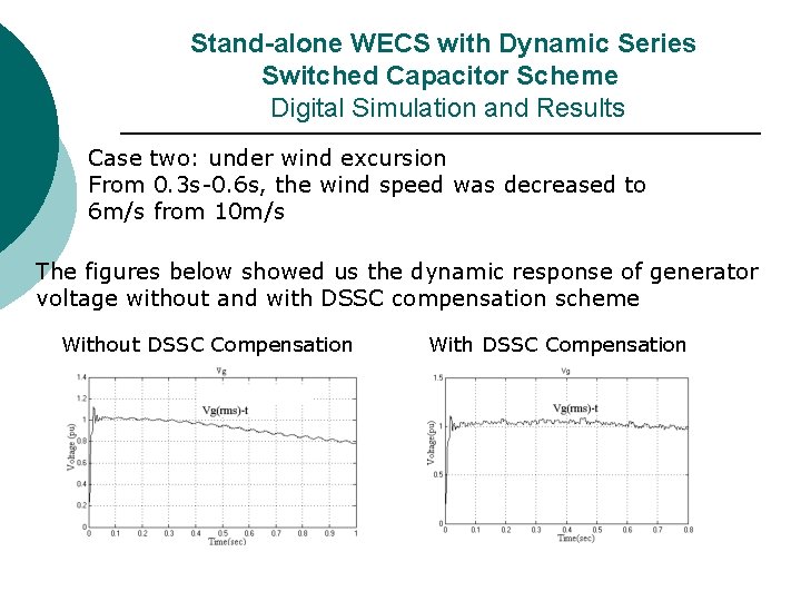
Stand-alone WECS with Dynamic Series Switched Capacitor Scheme Digital Simulation and Results Case two: under wind excursion From 0. 3 s-0. 6 s, the wind speed was decreased to 6 m/s from 10 m/s The figures below showed us the dynamic response of generator voltage without and with DSSC compensation scheme Without DSSC Compensation With DSSC Compensation
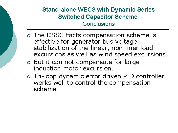
Stand-alone WECS with Dynamic Series Switched Capacitor Scheme Conclusions ¡ ¡ ¡ The DSSC Facts compensation scheme is effective for generator bus voltage stabilization of the linear, non-liner load excursions as well as wind speed excursions. But it can not compensate for large induction motor excursion. Tri-loop dynamic error driven PID controller works well to control the compensation scheme
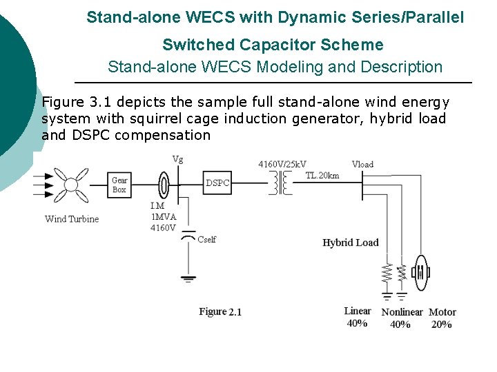
Stand-alone WECS with Dynamic Series/Parallel Switched Capacitor Scheme Stand-alone WECS Modeling and Description Figure 3. 1 depicts the sample full stand-alone wind energy system with squirrel cage induction generator, hybrid load and DSPC compensation
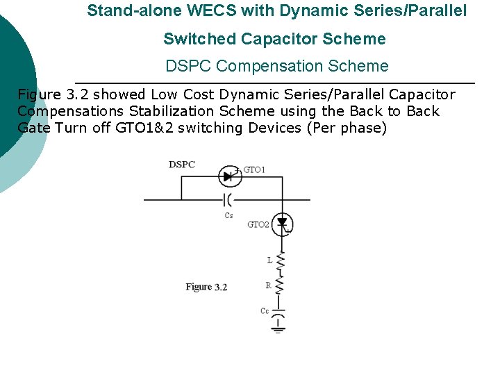
Stand-alone WECS with Dynamic Series/Parallel Switched Capacitor Scheme DSPC Compensation Scheme Figure 3. 2 showed Low Cost Dynamic Series/Parallel Capacitor Compensations Stabilization Scheme using the Back to Back Gate Turn off GTO 1&2 switching Devices (Per phase)
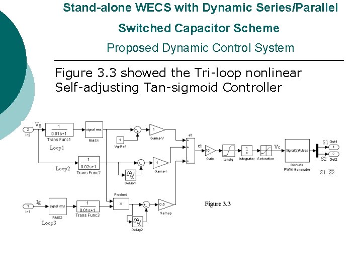
Stand-alone WECS with Dynamic Series/Parallel Switched Capacitor Scheme Proposed Dynamic Control System Figure 3. 3 showed the Tri-loop nonlinear Self-adjusting Tan-sigmoid Controller
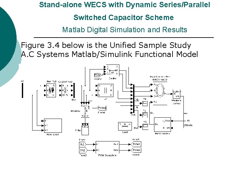
Stand-alone WECS with Dynamic Series/Parallel Switched Capacitor Scheme Matlab Digital Simulation and Results Figure 3. 4 below is the Unified Sample Study A. C Systems Matlab/Simulink Functional Model
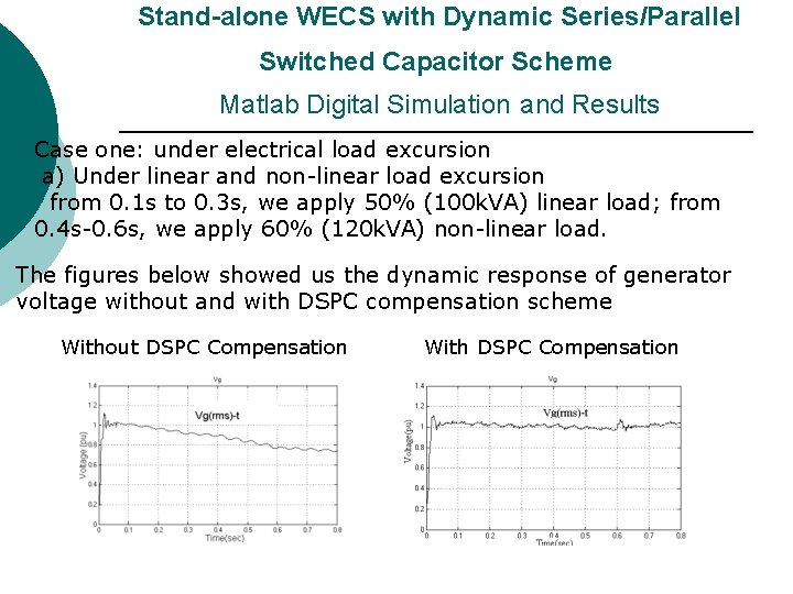
Stand-alone WECS with Dynamic Series/Parallel Switched Capacitor Scheme Matlab Digital Simulation and Results Case one: under electrical load excursion a) Under linear and non-linear load excursion from 0. 1 s to 0. 3 s, we apply 50% (100 k. VA) linear load; from 0. 4 s-0. 6 s, we apply 60% (120 k. VA) non-linear load. The figures below showed us the dynamic response of generator voltage without and with DSPC compensation scheme Without DSPC Compensation With DSPC Compensation
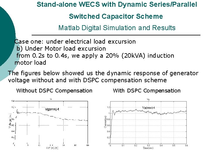
Stand-alone WECS with Dynamic Series/Parallel Switched Capacitor Scheme Matlab Digital Simulation and Results Case one: under electrical load excursion b) Under Motor load excursion from 0. 2 s to 0. 4 s, we apply a 20% (20 k. VA) induction motor load The figures below showed us the dynamic response of generator voltage without and with DSPC compensation scheme Without DSPC Compensation With DSPC Compensation
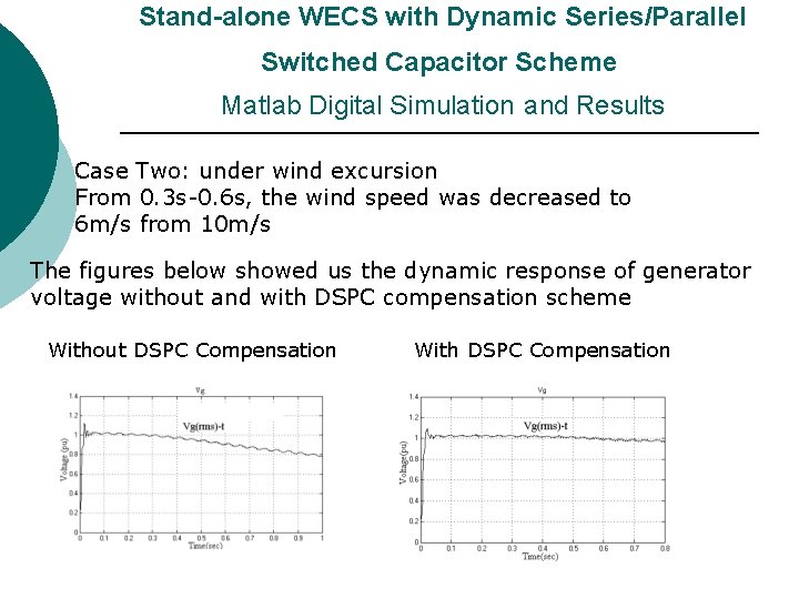
Stand-alone WECS with Dynamic Series/Parallel Switched Capacitor Scheme Matlab Digital Simulation and Results Case Two: under wind excursion From 0. 3 s-0. 6 s, the wind speed was decreased to 6 m/s from 10 m/s The figures below showed us the dynamic response of generator voltage without and with DSPC compensation scheme Without DSPC Compensation With DSPC Compensation
Stand-alone WECS with Dynamic Series/Parallel Switched Capacitor Scheme Conclusions ¡ ¡ ¡ The Matllab/Simulink simulations validate that the DSPC compensation are very effective for the electric linear, non-liner, motor excursion and wind excursion. The proposed low cost DSPC voltage compensation scheme is suitable for isolated wind energy conversion systems feeding linear and non-liner and motor type loads The tri-loop nonlinear self-adjusting tansigmoid controller is effective for controlling the compensation scheme.
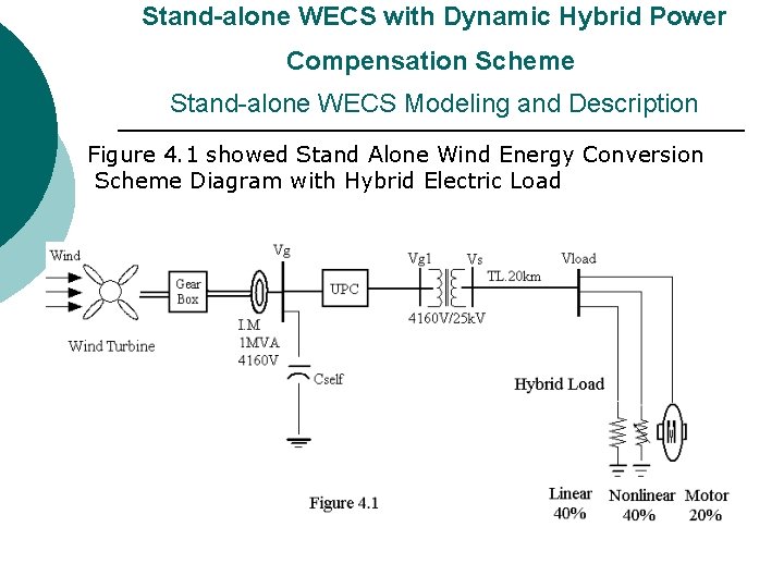
Stand-alone WECS with Dynamic Hybrid Power Compensation Scheme Stand-alone WECS Modeling and Description Figure 4. 1 showed Stand Alone Wind Energy Conversion Scheme Diagram with Hybrid Electric Load
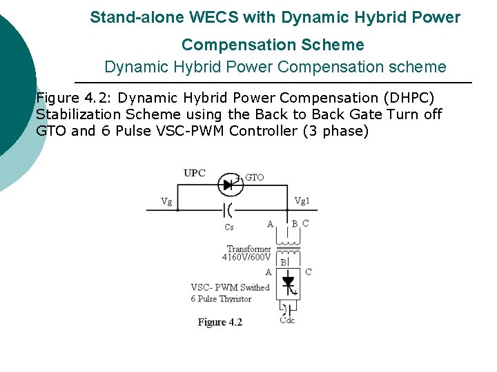
Stand-alone WECS with Dynamic Hybrid Power Compensation Scheme Dynamic Hybrid Power Compensation scheme Figure 4. 2: Dynamic Hybrid Power Compensation (DHPC) Stabilization Scheme using the Back to Back Gate Turn off GTO and 6 Pulse VSC-PWM Controller (3 phase)
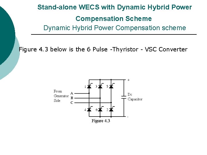
Stand-alone WECS with Dynamic Hybrid Power Compensation Scheme Dynamic Hybrid Power Compensation scheme Figure 4. 3 below is the 6 Pulse -Thyristor - VSC Converter
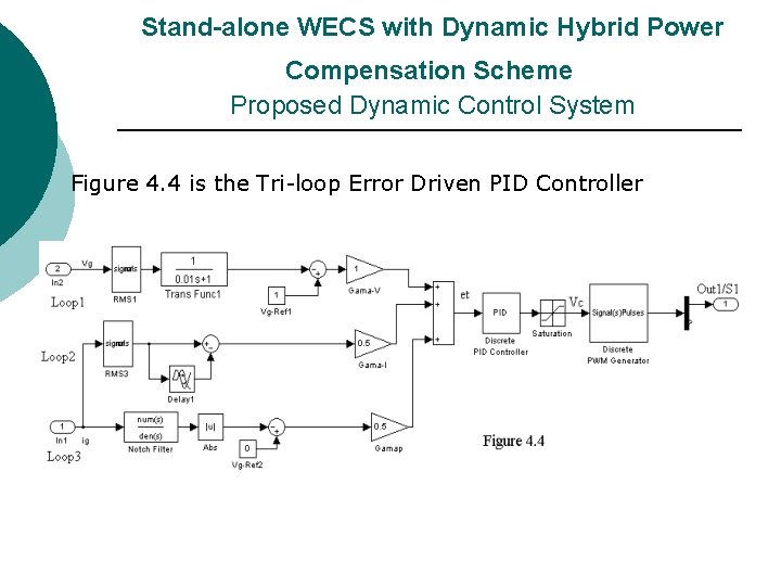
Stand-alone WECS with Dynamic Hybrid Power Compensation Scheme Proposed Dynamic Control System Figure 4. 4 is the Tri-loop Error Driven PID Controller
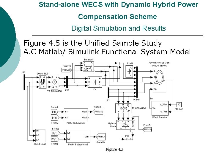
Stand-alone WECS with Dynamic Hybrid Power Compensation Scheme Digital Simulation and Results Figure 4. 5 is the Unified Sample Study A. C Matlab/ Simulink Functional System Model
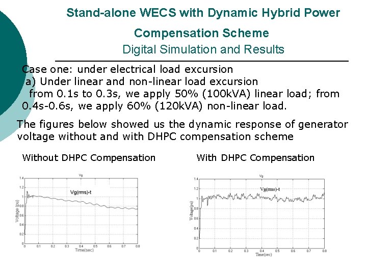
Stand-alone WECS with Dynamic Hybrid Power Compensation Scheme Digital Simulation and Results Case one: under electrical load excursion a) Under linear and non-linear load excursion from 0. 1 s to 0. 3 s, we apply 50% (100 k. VA) linear load; from 0. 4 s-0. 6 s, we apply 60% (120 k. VA) non-linear load. The figures below showed us the dynamic response of generator voltage without and with DHPC compensation scheme Without DHPC Compensation With DHPC Compensation
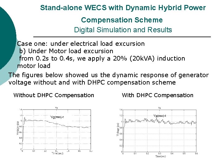
Stand-alone WECS with Dynamic Hybrid Power Compensation Scheme Digital Simulation and Results Case one: under electrical load excursion b) Under Motor load excursion from 0. 2 s to 0. 4 s, we apply a 20% (20 k. VA) induction motor load The figures below showed us the dynamic response of generator voltage without and with DHPC compensation scheme Without DHPC Compensation With DHPC Compensation
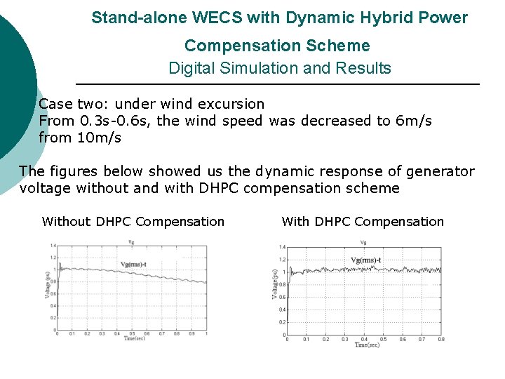
Stand-alone WECS with Dynamic Hybrid Power Compensation Scheme Digital Simulation and Results Case two: under wind excursion From 0. 3 s-0. 6 s, the wind speed was decreased to 6 m/s from 10 m/s The figures below showed us the dynamic response of generator voltage without and with DHPC compensation scheme Without DHPC Compensation With DHPC Compensation
Stand-alone WECS with Dynamic Hybrid Power Compensation Scheme Conclusions ¡ ¡ Digital simulation results validate that this new DHPC scheme is very effective for bus voltage stabilization under electric load disturbance including linear, nonlinear load and motor load excursions. The proposed novel tri-loop dynamic controller is very effective for the compensation scheme.
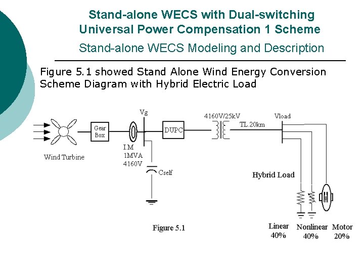
Stand-alone WECS with Dual-switching Universal Power Compensation 1 Scheme Stand-alone WECS Modeling and Description Figure 5. 1 showed Stand Alone Wind Energy Conversion Scheme Diagram with Hybrid Electric Load
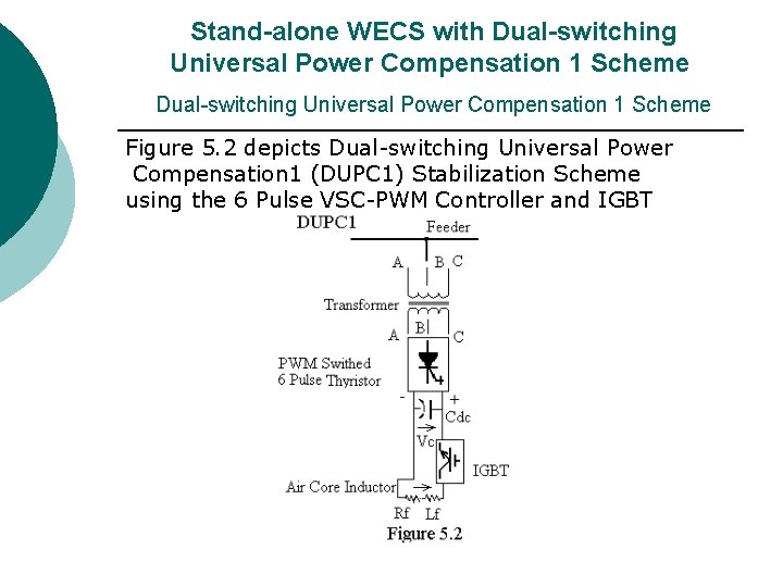
Stand-alone WECS with Dual-switching Universal Power Compensation 1 Scheme Figure 5. 2 depicts Dual-switching Universal Power Compensation 1 (DUPC 1) Stabilization Scheme using the 6 Pulse VSC-PWM Controller and IGBT
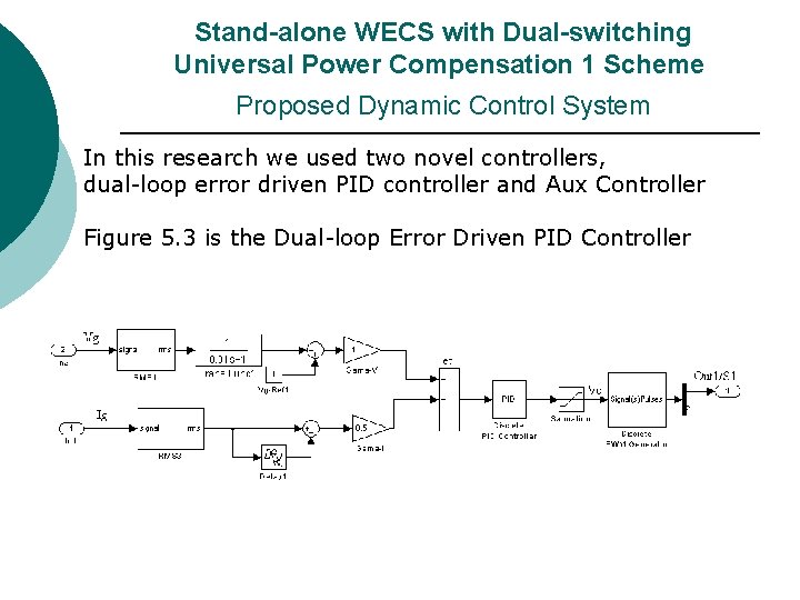
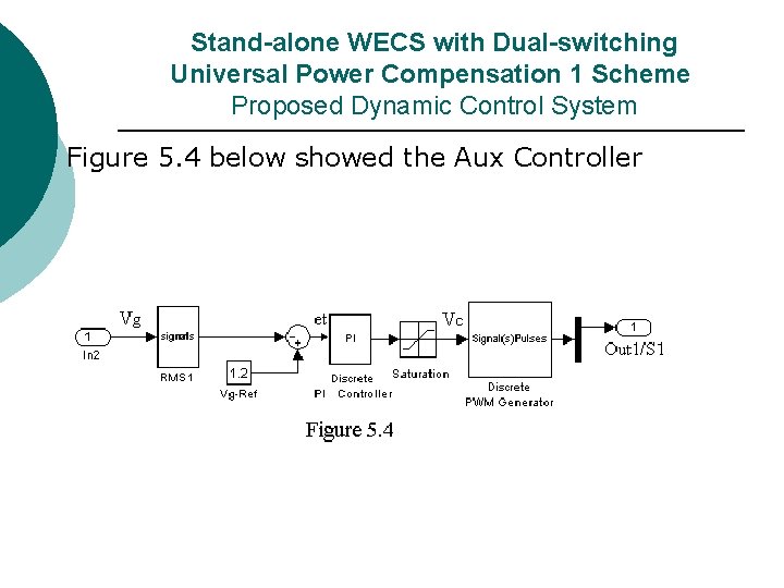
Stand-alone WECS with Dual-switching Universal Power Compensation 1 Scheme Proposed Dynamic Control System In this research we used two novel controllers, dual-loop error driven PID controller and Aux Controller Figure 5. 3 is the Dual-loop Error Driven PID Controller
Stand-alone WECS with Dual-switching Universal Power Compensation 1 Scheme Proposed Dynamic Control System Figure 5. 4 below showed the Aux Controller
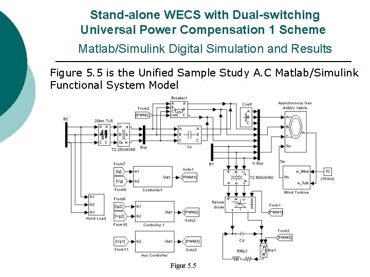
Stand-alone WECS with Dual-switching Universal Power Compensation 1 Scheme Matlab/Simulink Digital Simulation and Results Figure 5. 5 is the Unified Sample Study A. C Matlab/Simulink Functional System Model
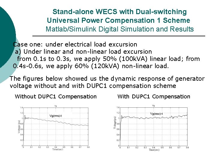
Stand-alone WECS with Dual-switching Universal Power Compensation 1 Scheme Matlab/Simulink Digital Simulation and Results Case one: under electrical load excursion a) Under linear and non-linear load excursion from 0. 1 s to 0. 3 s, we apply 50% (100 k. VA) linear load; from 0. 4 s-0. 6 s, we apply 60% (120 k. VA) non-linear load. The figures below showed us the dynamic response of generator voltage without and with DUPC 1 compensation scheme Without DUPC 1 Compensation With DUPC 1 Compensation
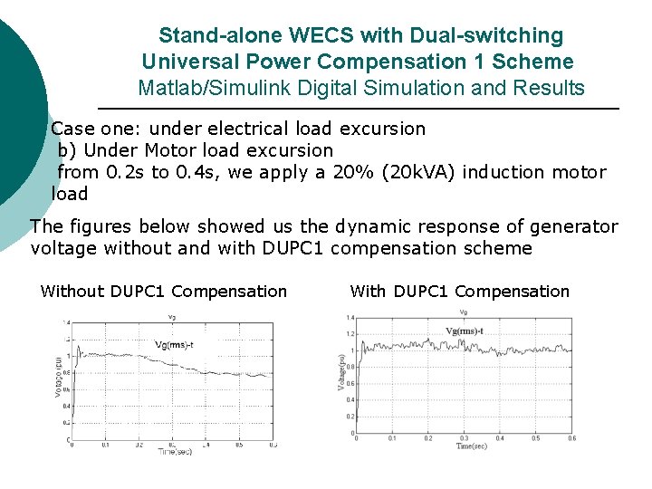
Stand-alone WECS with Dual-switching Universal Power Compensation 1 Scheme Matlab/Simulink Digital Simulation and Results Case one: under electrical load excursion b) Under Motor load excursion from 0. 2 s to 0. 4 s, we apply a 20% (20 k. VA) induction motor load The figures below showed us the dynamic response of generator voltage without and with DUPC 1 compensation scheme Without DUPC 1 Compensation With DUPC 1 Compensation
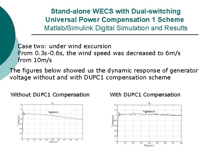
Stand-alone WECS with Dual-switching Universal Power Compensation 1 Scheme Matlab/Simulink Digital Simulation and Results Case two: under wind excursion From 0. 3 s-0. 6 s, the wind speed was decreased to 6 m/s from 10 m/s The figures below showed us the dynamic response of generator voltage without and with DUPC 1 compensation scheme Without DUPC 1 Compensation With DUPC 1 Compensation
Stand-alone WECS with Dual-switching Universal Power Compensation 1 Scheme Conclusions ¡ ¡ This new DUPC 1 compensator scheme is very effective in stabilizing generator bus voltage as well as enhancing power/energy utilization under favorable wind gusting conditions The novel dual-loop dynamic controller is extremely flexible and can be easily modified to include other supplementary loops such as generator power
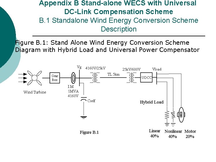
Appendix B Stand-alone WECS with Universal DC-Link Compensation Scheme B. 1 Standalone Wind Energy Conversion Scheme Description Figure B. 1: Stand Alone Wind Energy Conversion Scheme Diagram with Hybrid Load and Universal Power Compensator
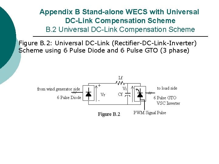
Appendix B Stand-alone WECS with Universal DC-Link Compensation Scheme B. 2 Universal DC-Link Compensation Scheme Figure B. 2: Universal DC-Link (Rectifier-DC-Link-Inverter) Scheme using 6 Pulse Diode and 6 Pulse GTO (3 phase)
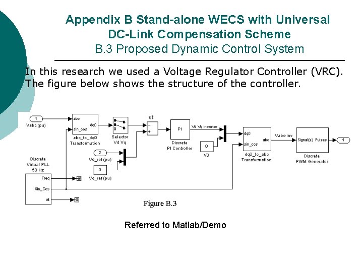
Appendix B Stand-alone WECS with Universal DC-Link Compensation Scheme B. 3 Proposed Dynamic Control System In this research we used a Voltage Regulator Controller (VRC). The figure below shows the structure of the controller. Referred to Matlab/Demo
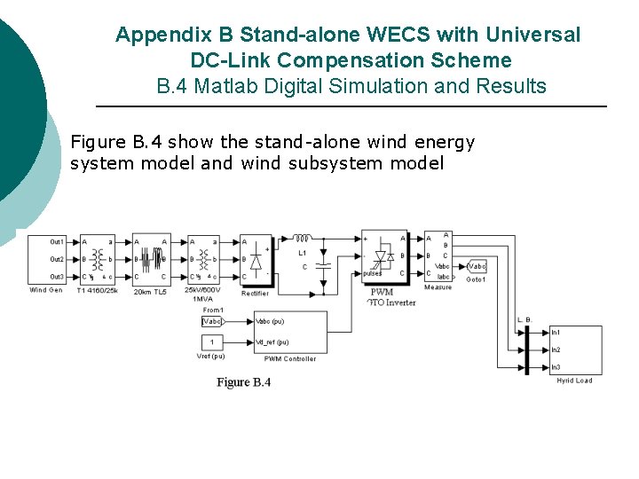
Appendix B Stand-alone WECS with Universal DC-Link Compensation Scheme B. 4 Matlab Digital Simulation and Results Figure B. 4 show the stand-alone wind energy system model and wind subsystem model
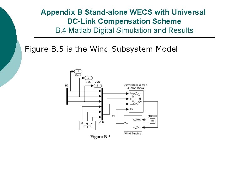
Appendix B Stand-alone WECS with Universal DC-Link Compensation Scheme B. 4 Matlab Digital Simulation and Results Figure B. 5 is the Wind Subsystem Model
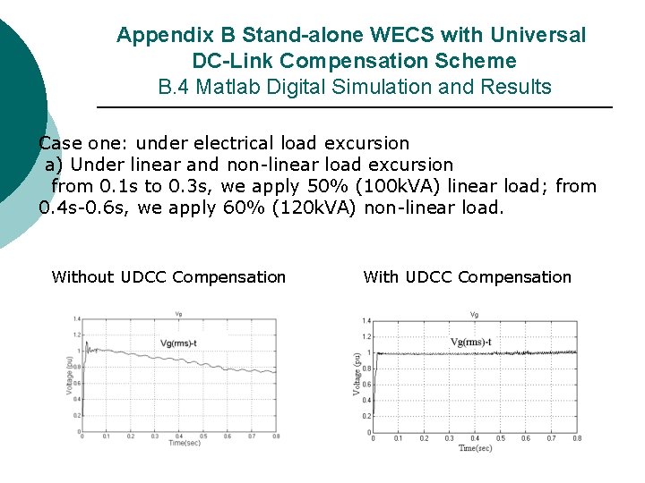
Appendix B Stand-alone WECS with Universal DC-Link Compensation Scheme B. 4 Matlab Digital Simulation and Results Case one: under electrical load excursion a) Under linear and non-linear load excursion from 0. 1 s to 0. 3 s, we apply 50% (100 k. VA) linear load; from 0. 4 s-0. 6 s, we apply 60% (120 k. VA) non-linear load. Without UDCC Compensation With UDCC Compensation
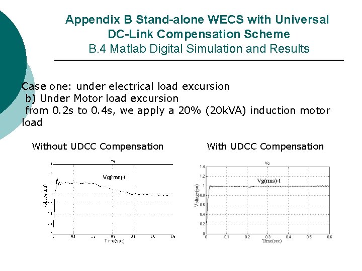
Appendix B Stand-alone WECS with Universal DC-Link Compensation Scheme B. 4 Matlab Digital Simulation and Results Case one: under electrical load excursion b) Under Motor load excursion from 0. 2 s to 0. 4 s, we apply a 20% (20 k. VA) induction motor load Without UDCC Compensation With UDCC Compensation
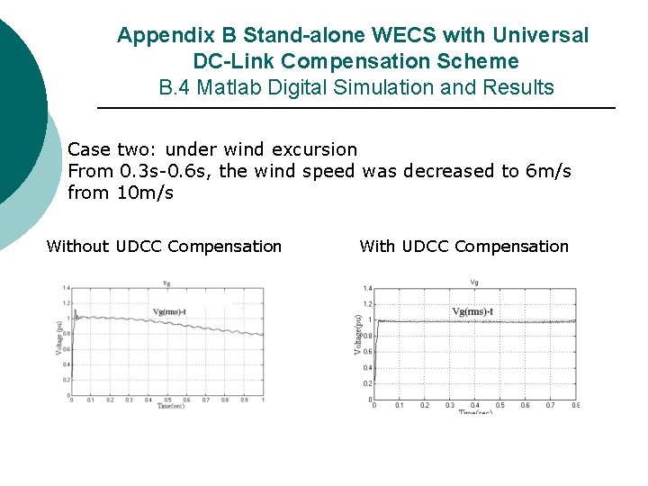
Appendix B Stand-alone WECS with Universal DC-Link Compensation Scheme B. 4 Matlab Digital Simulation and Results Case two: under wind excursion From 0. 3 s-0. 6 s, the wind speed was decreased to 6 m/s from 10 m/s Without UDCC Compensation With UDCC Compensation
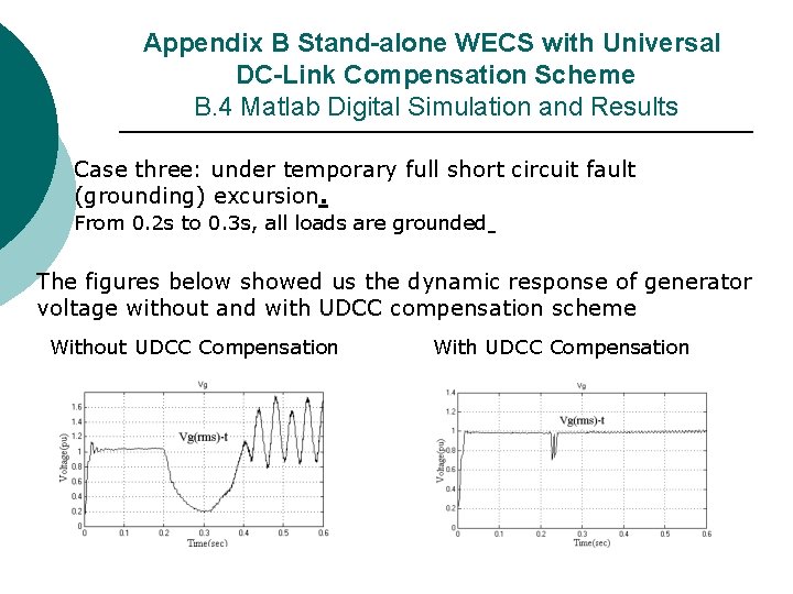
Appendix B Stand-alone WECS with Universal DC-Link Compensation Scheme B. 4 Matlab Digital Simulation and Results Case three: under temporary full short circuit fault (grounding) excursion. From 0. 2 s to 0. 3 s, all loads are grounded The figures below showed us the dynamic response of generator voltage without and with UDCC compensation scheme Without UDCC Compensation With UDCC Compensation
Appendix B Stand-alone WECS with Universal DC-Link Compensation Scheme B. 5 Conclusions ¡ ¡ ¡ This new UDCC compensator scheme is very effective in stabilizing the generator bus voltage under all electric loads and wind gusting conditions as well as full three phase short circuit fault. the UDCC Facts-device showed its special advantage that it can compensate for full three phase short circuit fault. The Voltage stabilization is complex and suitable in large wind farm utilization scheme with one load collection center
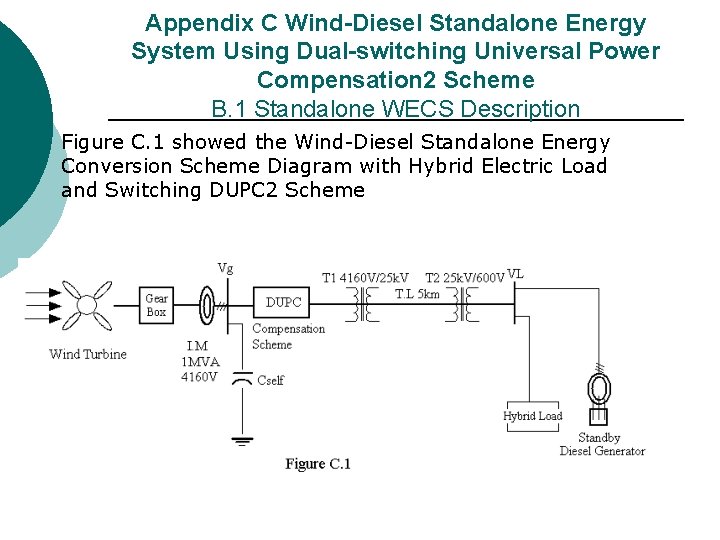
Appendix C Wind-Diesel Standalone Energy System Using Dual-switching Universal Power Compensation 2 Scheme B. 1 Standalone WECS Description Figure C. 1 showed the Wind-Diesel Standalone Energy Conversion Scheme Diagram with Hybrid Electric Load and Switching DUPC 2 Scheme
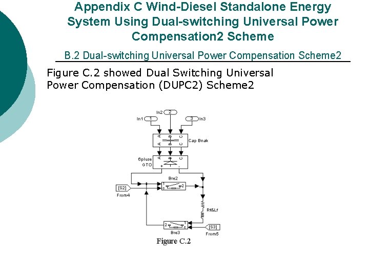
Appendix C Wind-Diesel Standalone Energy System Using Dual-switching Universal Power Compensation 2 Scheme B. 2 Dual-switching Universal Power Compensation Scheme 2 Figure C. 2 showed Dual Switching Universal Power Compensation (DUPC 2) Scheme 2
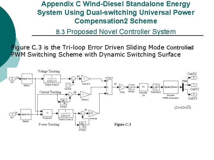
Appendix C Wind-Diesel Standalone Energy System Using Dual-switching Universal Power Compensation 2 Scheme B. 3 Proposed Novel Controller System Figure C. 3 is the Tri-loop Error Driven Sliding Mode Controlled PWM Switching Scheme with Dynamic Switching Surface
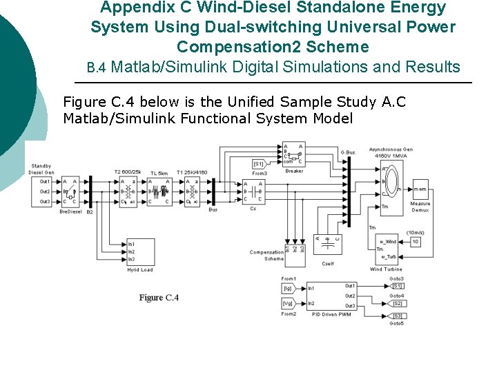
Appendix C Wind-Diesel Standalone Energy System Using Dual-switching Universal Power Compensation 2 Scheme B. 4 Matlab/Simulink Digital Simulations and Results Figure C. 4 below is the Unified Sample Study A. C Matlab/Simulink Functional System Model
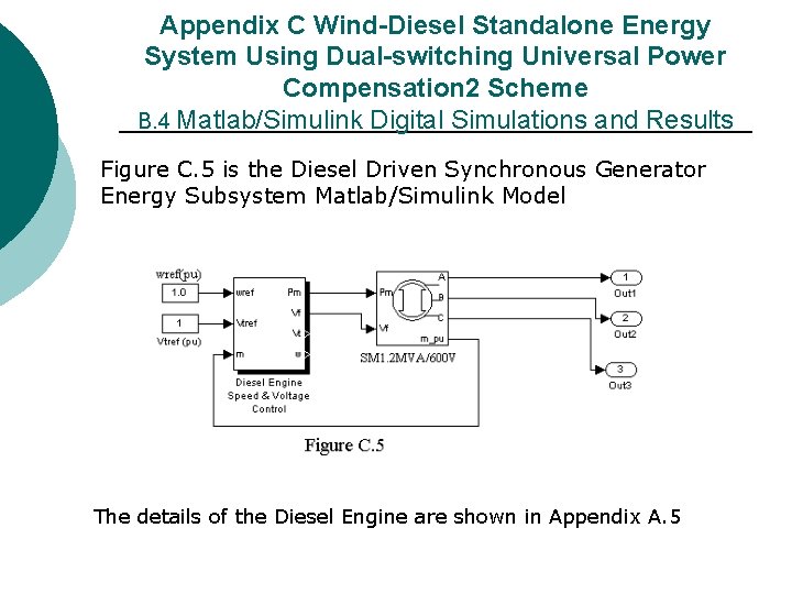
Appendix C Wind-Diesel Standalone Energy System Using Dual-switching Universal Power Compensation 2 Scheme B. 4 Matlab/Simulink Digital Simulations and Results Figure C. 5 is the Diesel Driven Synchronous Generator Energy Subsystem Matlab/Simulink Model The details of the Diesel Engine are shown in Appendix A. 5
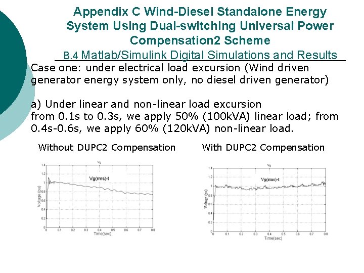
Appendix C Wind-Diesel Standalone Energy System Using Dual-switching Universal Power Compensation 2 Scheme B. 4 Matlab/Simulink Digital Simulations and Results Case one: under electrical load excursion (Wind driven generator energy system only, no diesel driven generator) a) Under linear and non-linear load excursion from 0. 1 s to 0. 3 s, we apply 50% (100 k. VA) linear load; from 0. 4 s-0. 6 s, we apply 60% (120 k. VA) non-linear load. Without DUPC 2 Compensation With DUPC 2 Compensation
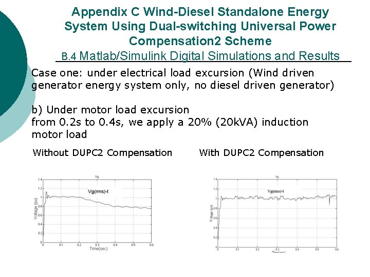
Appendix C Wind-Diesel Standalone Energy System Using Dual-switching Universal Power Compensation 2 Scheme B. 4 Matlab/Simulink Digital Simulations and Results Case one: under electrical load excursion (Wind driven generator energy system only, no diesel driven generator) b) Under motor load excursion from 0. 2 s to 0. 4 s, we apply a 20% (20 k. VA) induction motor load Without DUPC 2 Compensation With DUPC 2 Compensation
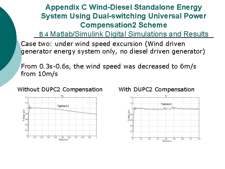
Appendix C Wind-Diesel Standalone Energy System Using Dual-switching Universal Power Compensation 2 Scheme B. 4 Matlab/Simulink Digital Simulations and Results Case two: under wind speed excursion (Wind driven generator energy system only, no diesel driven generator) From 0. 3 s-0. 6 s, the wind speed was decreased to 6 m/s from 10 m/s Without DUPC 2 Compensation With DUPC 2 Compensation
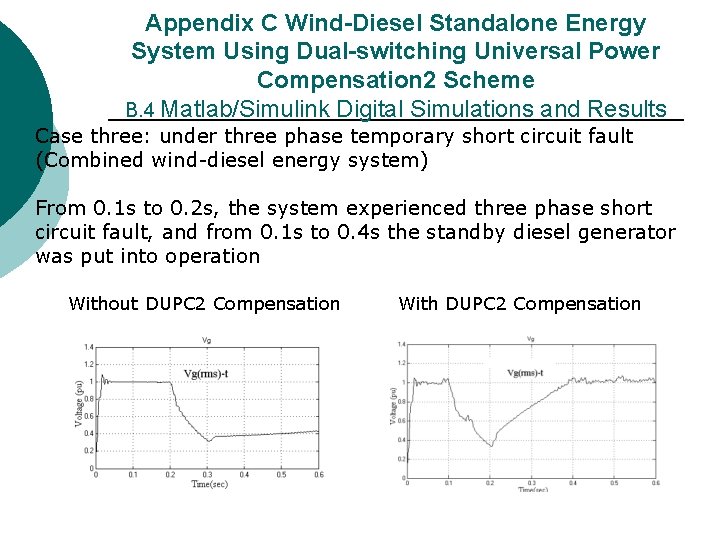
Appendix C Wind-Diesel Standalone Energy System Using Dual-switching Universal Power Compensation 2 Scheme B. 4 Matlab/Simulink Digital Simulations and Results Case three: under three phase temporary short circuit fault (Combined wind-diesel energy system) From 0. 1 s to 0. 2 s, the system experienced three phase short circuit fault, and from 0. 1 s to 0. 4 s the standby diesel generator was put into operation Without DUPC 2 Compensation With DUPC 2 Compensation
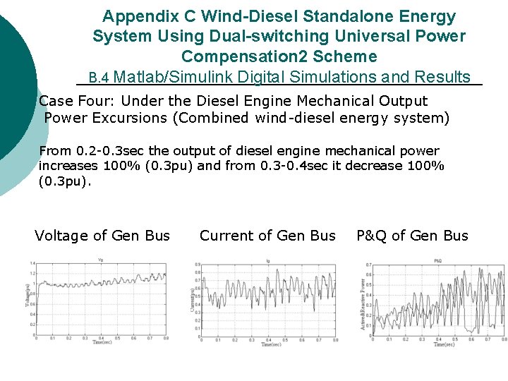
Appendix C Wind-Diesel Standalone Energy System Using Dual-switching Universal Power Compensation 2 Scheme B. 4 Matlab/Simulink Digital Simulations and Results Case Four: Under the Diesel Engine Mechanical Output Power Excursions (Combined wind-diesel energy system) From 0. 2 -0. 3 sec the output of diesel engine mechanical power increases 100% (0. 3 pu) and from 0. 3 -0. 4 sec it decrease 100% (0. 3 pu). Voltage of Gen Bus Current of Gen Bus P&Q of Gen Bus
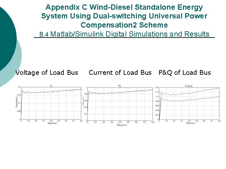
Appendix C Wind-Diesel Standalone Energy System Using Dual-switching Universal Power Compensation 2 Scheme B. 4 Matlab/Simulink Digital Simulations and Results Voltage of Load Bus Current of Load Bus P&Q of Load Bus
Appendix C Wind-Diesel Standalone Energy System Using Dual-switching Universal Power Compensation 2 Scheme B. 5 Conclusions ¡ ¡ ¡ The DUPC 2 compensation scheme is very effective for voltage stabilization under the linear, non-liner and motor load excursions as well as wind speed and diesel on-off excursions. During emergency three phase short circuit fault condition, the standby diesel generator can keep the voltage of the generator bus at 1. 0 pu. The proposed wind/ diesel energy system combined with stabilization scheme DUPC 2 is fully suitable for all isolated wind energy conversion systems in the range 0. 5 -2 MW.
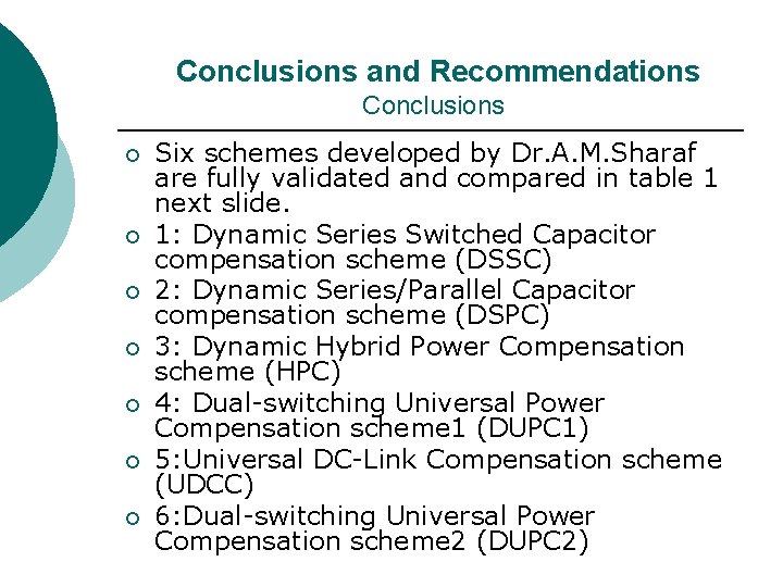
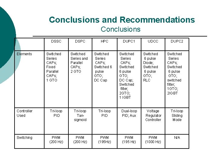
Conclusions and Recommendations Conclusions ¡ ¡ ¡ ¡ Six schemes developed by Dr. A. M. Sharaf are fully validated and compared in table 1 next slide. 1: Dynamic Series Switched Capacitor compensation scheme (DSSC) 2: Dynamic Series/Parallel Capacitor compensation scheme (DSPC) 3: Dynamic Hybrid Power Compensation scheme (HPC) 4: Dual-switching Universal Power Compensation scheme 1 (DUPC 1) 5: Universal DC-Link Compensation scheme (UDCC) 6: Dual-switching Universal Power Compensation scheme 2 (DUPC 2)
Conclusions and Recommendations Conclusions DSSC Elements Switched Series CAPs; Fixed Parallel CAPs; 1 GTO DSPC Switched Series and Parallel CAPs; 2 GTO HPC Switched Series CAPs; Switched 6 pulse GTO; DC Cap DUPC 1 UDCC DUPC 2 Switched Series CAPs; Switched 6 pulse GTO; DC Cap; Switched filter; 2 GTO; 1 IGBT Switched 6 pulse Diode; Switched 6 pulse GTO; RLC Switched Series CAPs; Switched 6 pulse GTO; switched filter; 1 GTO; 2 IGBT Controller Used Tri-loop PID Tri-loop Tansigmoid Tri-loop PID Dual-loop PID; Aux Voltage Regulator Controller Tri-loop Sliding Mode Switching PWM (200 Hz) PWM (195 Hz) PWM (195 Hz) PWM (1000 Hz) N/A
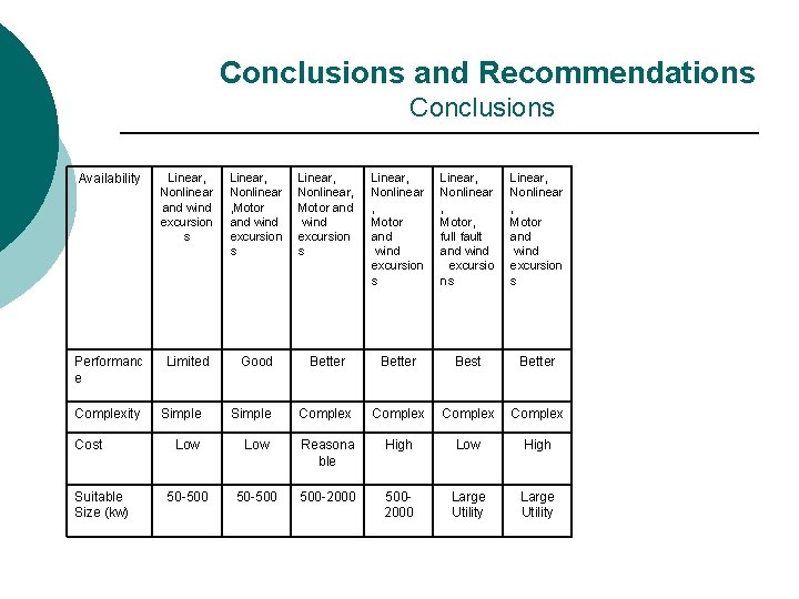
Conclusions and Recommendations Conclusions Availability Linear, Nonlinear and wind excursion s Linear, Nonlinear , Motor and wind excursion s Linear, Nonlinear , Motor, full fault and wind excursio ns Linear, Nonlinear , Motor and wind excursion s Performanc e Limited Good Better Best Better Complexity Cost Suitable Size (kw) Simple Complex Low Reasona ble High Low High 50 -500 500 -2000 5002000 Large Utility
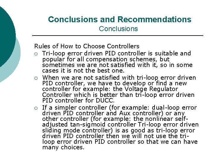
Conclusions and Recommendations Conclusions Rules of How to Choose Controllers ¡ Tri-loop error driven PID controller is suitable and popular for all compensation schemes, but sometimes we are not satisfied with it, so in some cases it is not the best one. ¡ When we are not satisfied with tri-loop error driven PID controller, we have to develop or find a new controller for example: the Voltage Regulator Controller which is better than tri-loop error driven PID controller for DUCC. ¡ If a simpler controller (for example: dual-loop error driven PID controller and Aux controller) or any other controller (for example: the nonlinear selfadjusted tan-sigmoid controller Tri-loop error driven sliding mode controller) is as good as tri-loop error driven PID controller then we will not use the triloop error driven PID controller so that we can have many choices.
Conclusions and Recommendations Extensions ¡ ¡ The proposed novel stabilization schemes can be extended to other hybrid energy schemes such as solar/small hydro/microgas/hydrogen fired turbine/biomass/fuel cell, microgas turbines and hybrid systems. The era of hydrogen technology is dawning with new hybrid fuel technologies using PV/Wind/ Small Hydro to produce hydrogen from water. This hydrogen will be used in remote sites in producing electricity via Fuel Cell large units
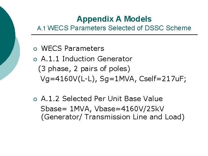
Appendix A Models A. 1 WECS Parameters Selected of DSSC Scheme WECS Parameters ¡ A. 1. 1 Induction Generator (3 phase, 2 pairs of poles) Vg=4160 V(L-L), Sg=1 MVA, Cself=217 u. F; ¡ A. 1. 2 Selected Per Unit Base Value Sbase= 1 MVA, Vbase=4160 V/25 k. V (Generator/ Transmission Line and Load) ¡
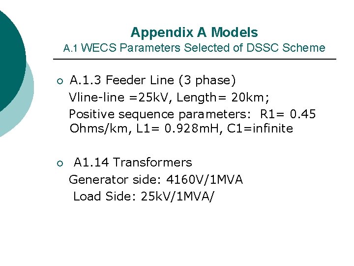
Appendix A Models A. 1 WECS Parameters Selected of DSSC Scheme A. 1. 3 Feeder Line (3 phase) Vline-line =25 k. V, Length= 20 km; Positive sequence parameters: R 1= 0. 45 Ohms/km, L 1= 0. 928 m. H, C 1=infinite ¡ A 1. 14 Transformers Generator side: 4160 V/1 MVA Load Side: 25 k. V/1 MVA/ ¡
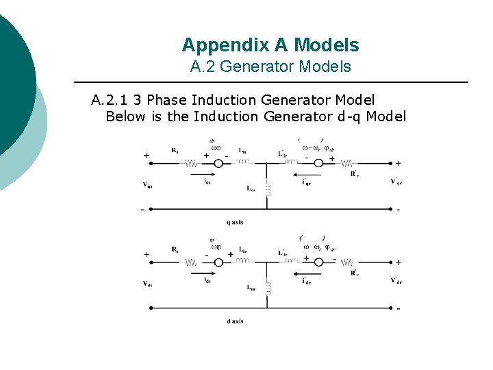
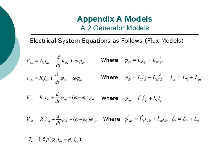
Appendix A Models A. 2 Generator Models A. 2. 1 3 Phase Induction Generator Model Below is the Induction Generator d-q Model
Appendix A Models A. 2 Generator Models Electrical System Equations as Follows (Flux Models) Where
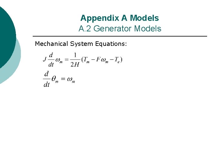
Appendix A Models A. 2 Generator Models Mechanical System Equations:
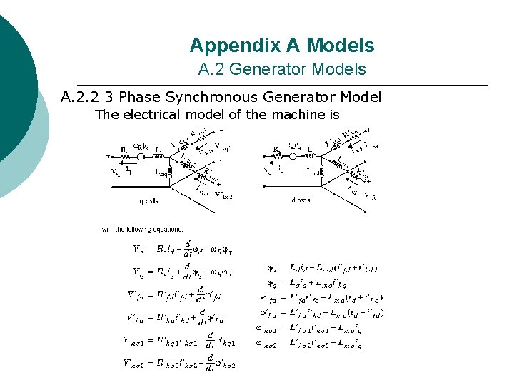
Appendix A Models A. 2 Generator Models A. 2. 2 3 Phase Synchronous Generator Model The electrical model of the machine is
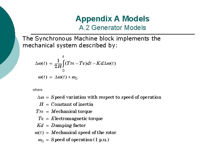
Appendix A Models A. 2 Generator Models The Synchronous Machine block implements the mechanical system described by:
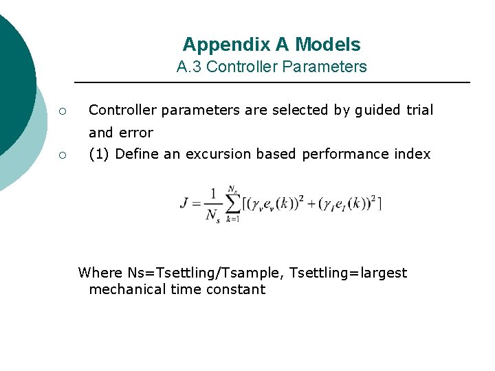
Appendix A Models A. 3 Controller Parameters ¡ Controller parameters are selected by guided trial and error ¡ (1) Define an excursion based performance index Where Ns=Tsettling/Tsample, Tsettling=largest mechanical time constant
Appendix A Models A. 3 Controller Parameters ¡ ¡ (2) Select control loop weightings (gamma) to reflect the controller main objective, with the assign the largest loop weight for the voltage loop stabilization. (3) Select different delay times to ensure multiloop-decoupling and the control priority assignment, ensure dynamic tracking error delay of half cycle for the fast electrical loops and few cycles for the slow mechanical loops. (4) Avoid the creation of any near resonance condition (5) Avoid any control loop/system unstable interaction by ensuring full control loop-decoupling of the multi-loop structure
Appendix A Models A. 3 Controller Parameters ¡ (6) Select the controller PID parameters to ensure fast controllability and voltage stabilization as well as short settling time (Kd is very small, if used) ¡ (7) Minimize the index J under a number of sequenced wind and load excursions over a selected settling time (1 -2 times the largest time constant in the system) ¡ (8) Repeat the optimization guided procedure until delta error especially voltage is within maximum + - 10 % in a short settling period and max wind power is somewhat extracted also no severe oscillations in the dynamic response, damped or over-damped dynamic response.
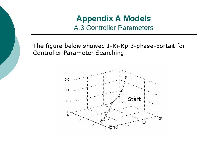
Appendix A Models A. 3 Controller Parameters The figure below showed J-Ki-Kp 3 -phase-portait for Controller Parameter Searching Start End
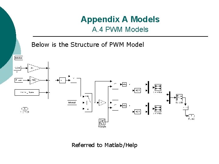
Appendix A Models A. 4 PWM Models Below is the Structure of PWM Model Referred to Matlab/Help
Appendix A Models A. 4 PWM Models ¡ The PWM Generator block generates pulses for carrier-based pulse width modulation (PWM) systems. The block can be used to fire the selfcommuted devices (FETs, GTOs, or IGBTs) of singlephase, two-phase, three-phase, or a combination of two three-phase bridges. ¡ The number of pulses generated by the PWM Generator block is determined by the number of bridge arms you have to control
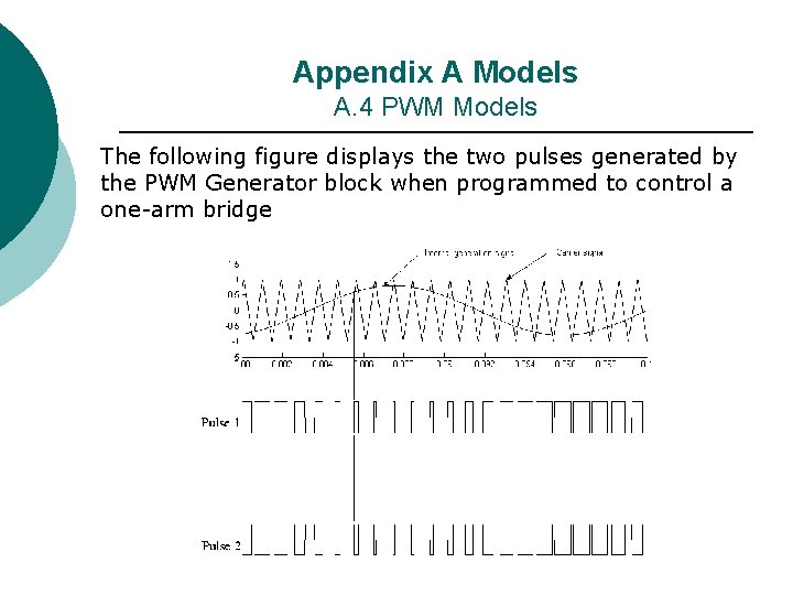
Appendix A Models A. 4 PWM Models ¡ ¡ The pulses are generated by comparing a triangular carrier waveform to a reference sinusoidal signal. The reference signal can be generated by the PWM generator itself, or it can be generated from a signal connected at the input of the block. In the second option, the PWM Generator needs one reference signal to generate the pulses for a single- or a twoarm bridge, or it needs a three-phase reference signal to generate the pulses for a three-phase bridge (single or double bridge The amplitude (modulation), phase, and frequency of the reference signals are set to control the output voltage (on the AC terminals) of the bridge connected to the PWM Generator block.
Appendix A Models A. 4 PWM Models The following figure displays the two pulses generated by the PWM Generator block when programmed to control a one-arm bridge
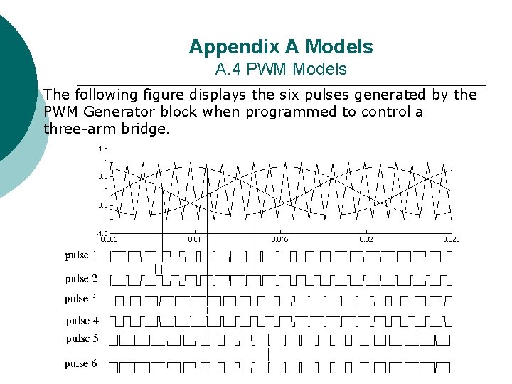
Appendix A Models A. 4 PWM Models The following figure displays the six pulses generated by the PWM Generator block when programmed to control a three-arm bridge.
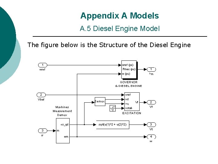
Appendix A Models A. 5 Diesel Engine Model The figure below is the Structure of the Diesel Engine
Appendix A Models A. 5 Diesel Engine Model ¡ ¡ ¡ The diesel engine comprises diesel engine & governor and excitation system. The diesel engine & governor include the control system, actuator and diesel engine; it inputs desired and actual speed, output diesel engine mechanical power. The excitation system provides excitation for the synchronous machine and regulates its terminal voltage. The first input of the block is the desired value of the stator terminal voltage. The following two inputs are the vsq and vsd components of the terminal voltage. The fourth input can be used to provide additional stabilization of power system oscillations.
Publications: ¡ ¡ ¡ A. M. Sharaf, and Liang Zhao, “A Low Cost Dynamic Voltage Stabilization Scheme for Stand Alone Wind Induction Generator System”. ICCCP 05 Oman (Accepted). A. M. Sharaf, Liang Zhao, “A Hybrid Power Compensation Scheme for Voltage Stabilization of Stand Alone Wind Induction Generator System”. CCECE 05 (Accepted). A. M. Sharaf, and Liang Zhao, “A Universal Power Compensation (UPC) Scheme for Voltage Stabilization of Stand Alone Wind Induction Generator System”, 2005 IEEE Conference on Control Applications, August 28 -31, 2005, Toronto, Canada. (Submitted) A. M. Sharaf, and Liang Zhao, “A Dual Switching Universal Power Compensation Scheme for Wind-Diesel Standalone Energy System”, 8 th International Conference on ‘Electrical Power Quality and Utilization’, Sep 21 -23, Cracow, Poland. (Submitted) A. M. Sharaf, and Liang Zhao, “Novel Control Strategies for Wind-Diesel Standalone Energy System Using Dual Switching Facts Universal Power Stabilization Scheme”, EPSR- Elsevier Jounal. (Submitted)
Dynamic Filter Compensator Schemes for Monitoring and Damping Subsynchronous Resonance Oscillations Prof. Dr. A. M. Sharaf Electrical and Computer Engineering Department
PRESENTATION OUTLINE Introduction ¡ Objectives ¡ Background review of SSR ¡ Modeling details for -Synchronous generators -Induction motors ¡ Sample dynamic simulation results ¡ Conclusions and future extensions ¡
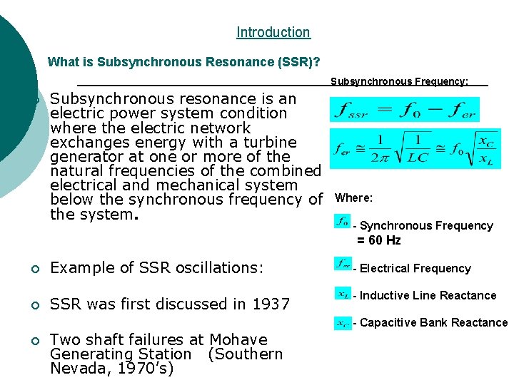
Introduction What is Subsynchronous Resonance (SSR)? Subsynchronous Frequency: ¡ Subsynchronous resonance is an electric power system condition where the electric network exchanges energy with a turbine generator at one or more of the natural frequencies of the combined electrical and mechanical system Where: below the synchronous frequency of the system. - Synchronous Frequency = 60 Hz Example of SSR oscillations: - Electrical Frequency ¡ SSR was first discussed in 1937 - Inductive Line Reactance - Capacitive Bank Reactance ¡ Two shaft failures at Mohave Generating Station (Southern Nevada, 1970’s) ¡
Objectives 1. Study Subsynchronous Resonance (SSR) oscillations for synchronous generators and large induction motors 2. Explore a new method to monitor SSR shaft torsional oscillations 3. Develop and validate a novel dynamic control scheme to damp SSR shaft torsional oscillations
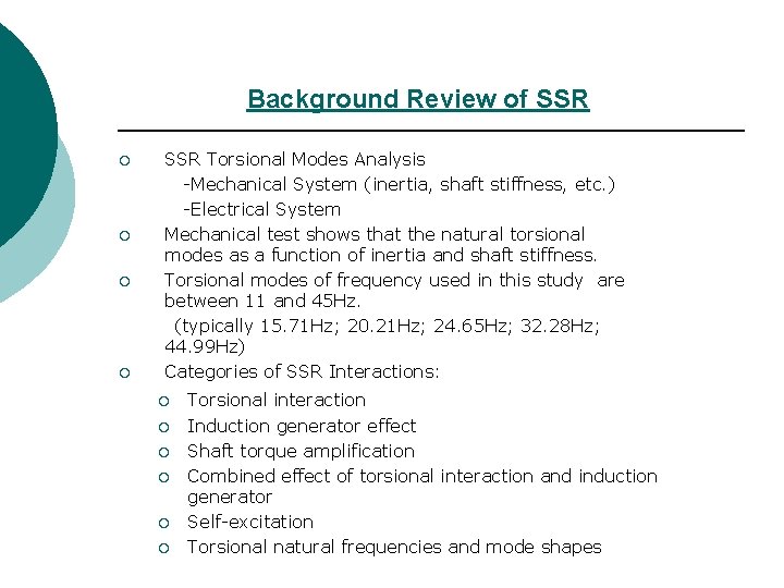
Background Review of SSR Torsional Modes Analysis -Mechanical System (inertia, shaft stiffness, etc. ) -Electrical System ¡ Mechanical test shows that the natural torsional modes as a function of inertia and shaft stiffness. ¡ Torsional modes of frequency used in this study are between 11 and 45 Hz. (typically 15. 71 Hz; 20. 21 Hz; 24. 65 Hz; 32. 28 Hz; 44. 99 Hz) ¡ Categories of SSR Interactions: ¡ ¡ ¡ ¡ Torsional interaction Induction generator effect Shaft torque amplification Combined effect of torsional interaction and induction generator Self-excitation Torsional natural frequencies and mode shapes
Background Review of SSR ¡ Other sources for excitation of SSR oscillations Ø Power System Stabilizer (PSS) Ø HVDC Converter Ø Static Var Compensator (SVC) Ø Variable Speed Drive Converter
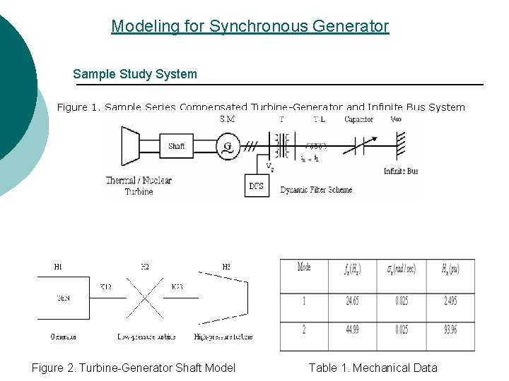
Modeling for Synchronous Generator Sample Study System Figure 1. Sample Series Compensated Turbine-Generator and Infinite Bus System Figure 2. Turbine-Generator Shaft Model Table 1. Mechanical Data
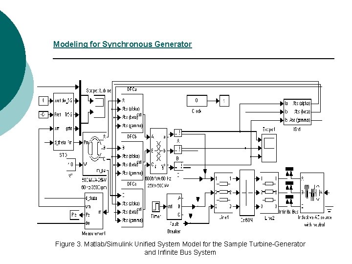
Modeling for Synchronous Generator Figure 3. Matlab/Simulink Unified System Model for the Sample Turbine-Generator and Infinite Bus System
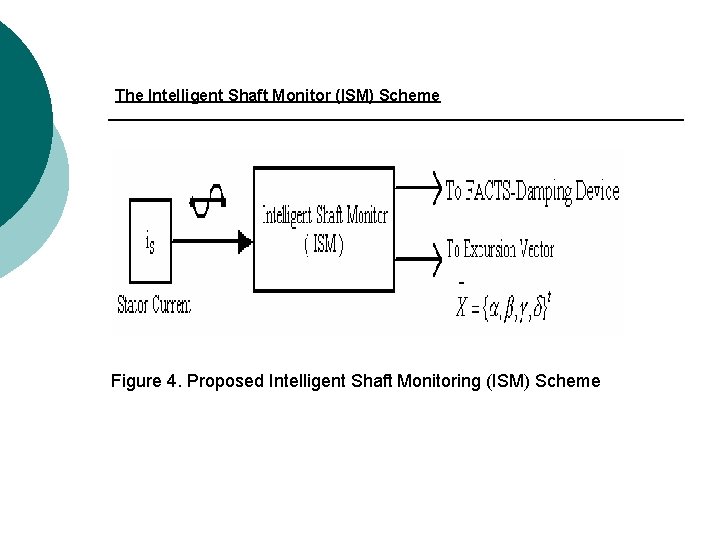
The Intelligent Shaft Monitor (ISM) Scheme Figure 4. Proposed Intelligent Shaft Monitoring (ISM) Scheme
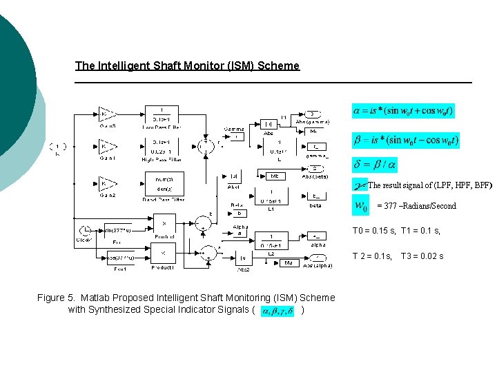
The Intelligent Shaft Monitor (ISM) Scheme - The result signal of (LPF, HPF, BPF) = 377 –Radians/Second T 0 = 0. 15 s, T 1 = 0. 1 s, T 2 = 0. 1 s, T 3 = 0. 02 s Figure 5. Matlab Proposed Intelligent Shaft Monitoring (ISM) Scheme with Synthesized Special Indicator Signals ( )
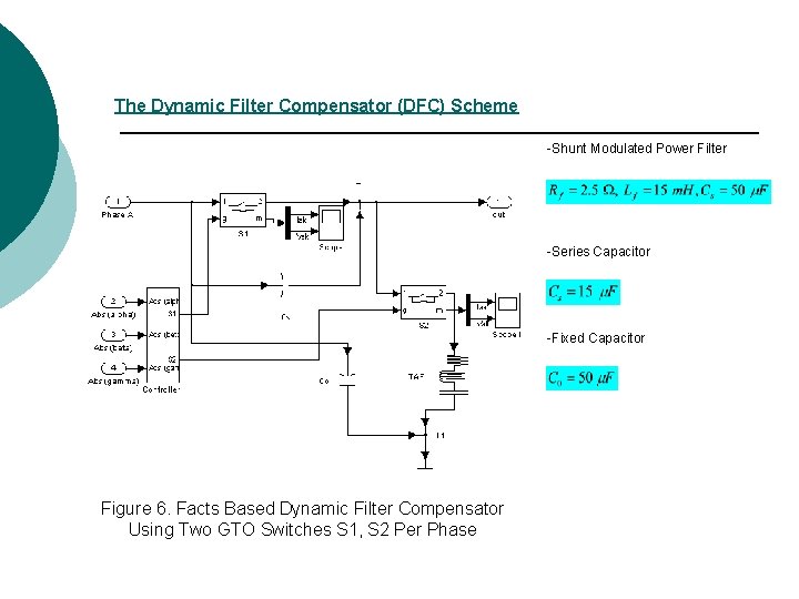
The Dynamic Filter Compensator (DFC) Scheme -Shunt Modulated Power Filter -Series Capacitor -Fixed Capacitor Figure 6. Facts Based Dynamic Filter Compensator Using Two GTO Switches S 1, S 2 Per Phase
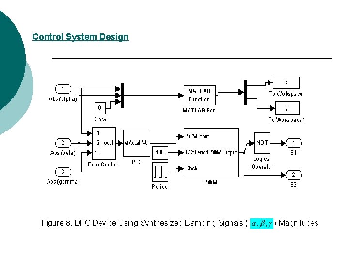
Control System Design Figure 8. DFC Device Using Synthesized Damping Signals ( ) Magnitudes
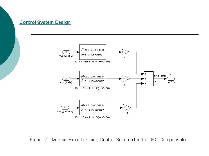
Control System Design Figure 7. Dynamic Error Tracking Control Scheme for the DFC Compensator
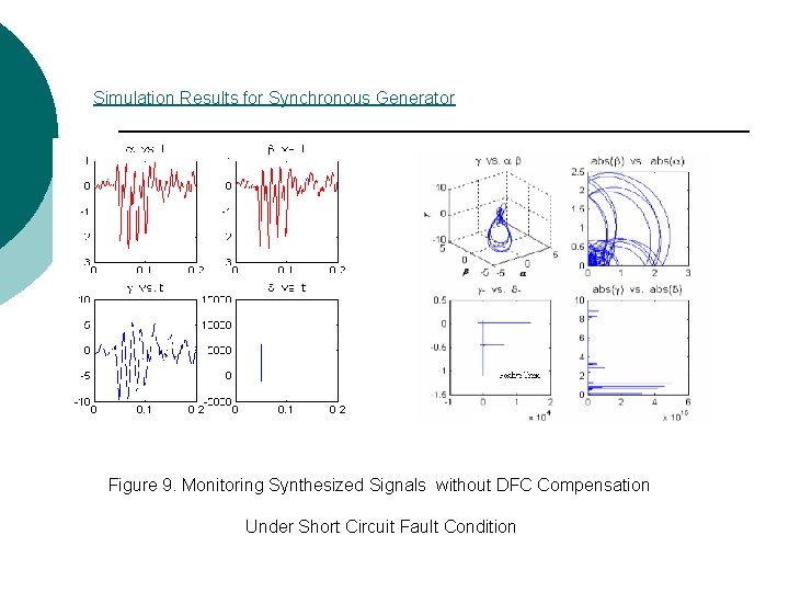
Simulation Results for Synchronous Generator Figure 9. Monitoring Synthesized Signals without DFC Compensation Under Short Circuit Fault Condition
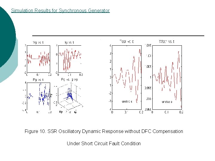
Simulation Results for Synchronous Generator Figure 10. SSR Oscillatory Dynamic Response without DFC Compensation Under Short Circuit Fault Condition
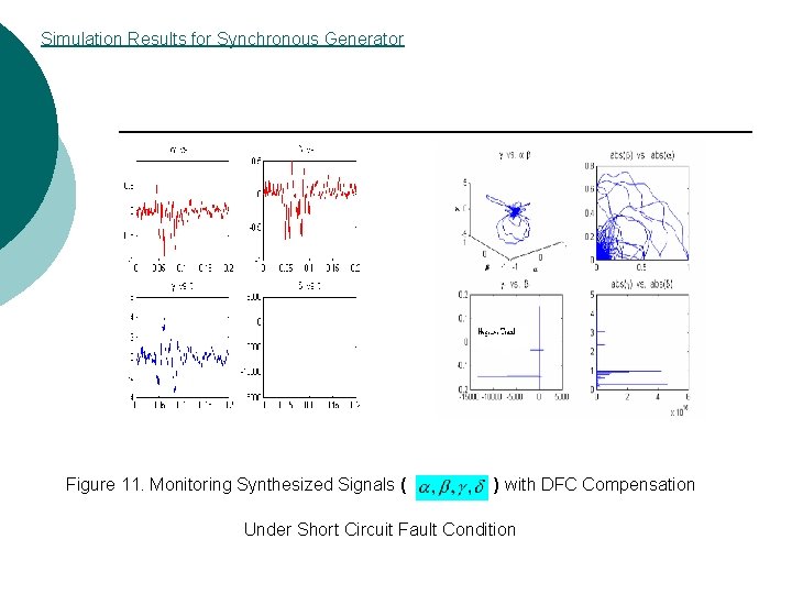
Simulation Results for Synchronous Generator Figure 11. Monitoring Synthesized Signals ( ) with DFC Compensation Under Short Circuit Fault Condition
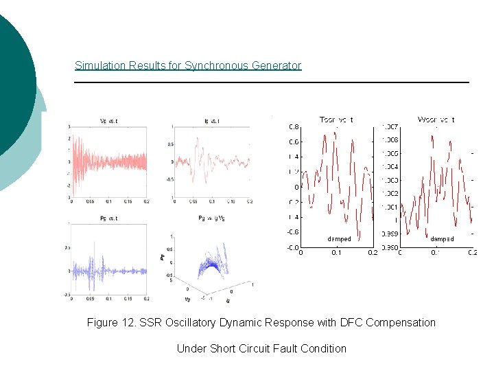
Simulation Results for Synchronous Generator Figure 12. SSR Oscillatory Dynamic Response with DFC Compensation Under Short Circuit Fault Condition
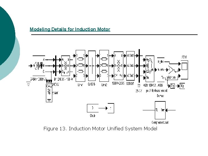
Modeling Details for Induction Motor Figure 13. Induction Motor Unified System Model
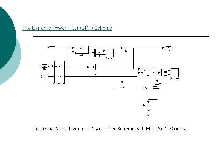
The Dynamic Power Filter (DPF) Scheme Figure 14. Novel Dynamic Power Filter Scheme with MPF/SCC Stages
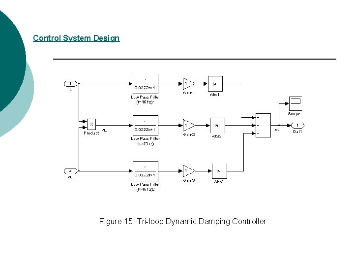
Control System Design Figure 15. Tri-loop Dynamic Damping Controller
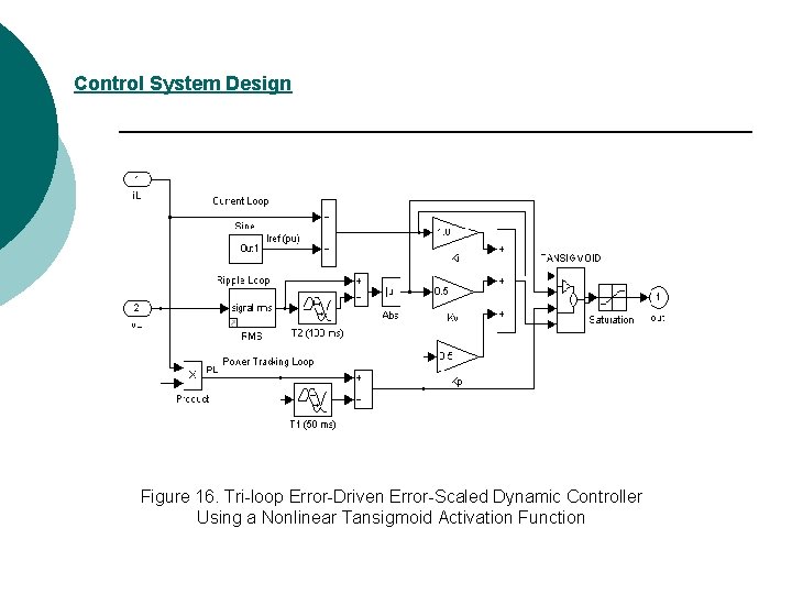
Control System Design Figure 16. Tri-loop Error-Driven Error-Scaled Dynamic Controller Using a Nonlinear Tansigmoid Activation Function
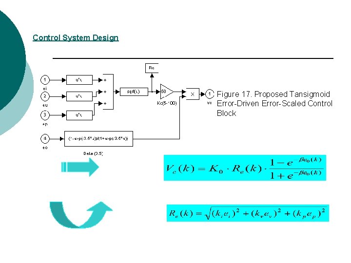
Control System Design Figure 17. Proposed Tansigmoid Error-Driven Error-Scaled Control Block
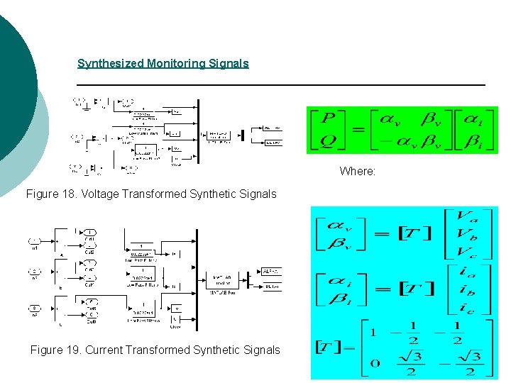
Synthesized Monitoring Signals Where: Figure 18. Voltage Transformed Synthetic Signals Figure 19. Current Transformed Synthetic Signals
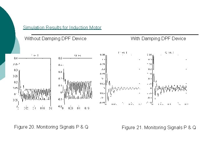
Simulation Results for Induction Motor Without Damping DPF Device Figure 20. Monitoring Signals P & Q With Damping DPF Device Figure 21. Monitoring Signals P & Q
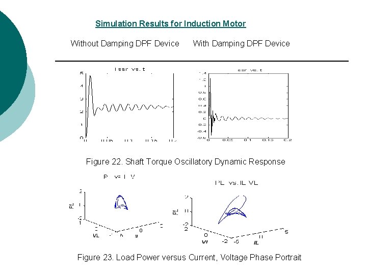
Simulation Results for Induction Motor Without Damping DPF Device With Damping DPF Device Figure 22. Shaft Torque Oscillatory Dynamic Response Figure 23. Load Power versus Current, Voltage Phase Portrait
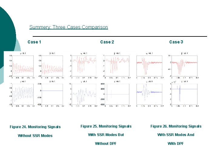
Summery: Three Cases Comparison Case 1 Case 2 Case 3 Figure 24. Monitoring Signals Figure 25. Monitoring Signals Figure 26. Monitoring Signals Without SSR Modes With SSR Modes But With SSR Modes And Without DPF With DPF
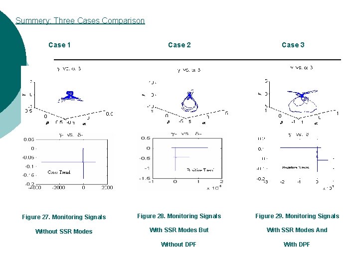
Summery: Three Cases Comparison Case 1 Case 2 Case 3 Figure 27. Monitoring Signals Figure 28. Monitoring Signals Figure 29. Monitoring Signals Without SSR Modes With SSR Modes But With SSR Modes And Without DPF With DPF
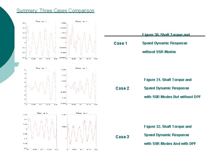
Summery: Three Cases Comparison Figure 30. Shaft Torque and Case 1 Speed Dynamic Response without SSR Modes Figure 31. Shaft Torque and Case 2 Speed Dynamic Response with SSR Modes But without DPF Figure 32. Shaft Torque and Case 3 Speed Dynamic Response with SSR Modes And with DPF
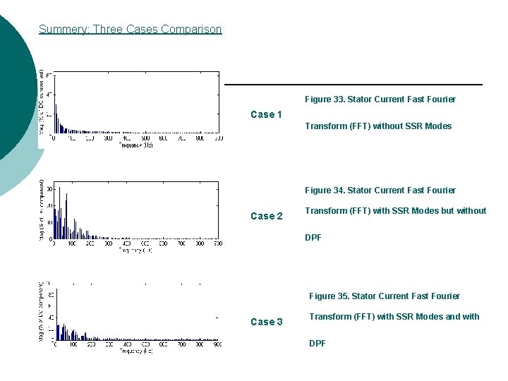
Summery: Three Cases Comparison Figure 33. Stator Current Fast Fourier Case 1 Transform (FFT) without SSR Modes Figure 34. Stator Current Fast Fourier Case 2 Transform (FFT) with SSR Modes but without DPF Figure 35. Stator Current Fast Fourier Case 3 Transform (FFT) with SSR Modes and with DPF
Conclusions and Future Extensions ¡ For both synchronous generators and induction motor drives, the SSR shaft torsional oscillations can be monitored using the online Intelligent Shaft Monitor (ISM) scheme. The ISM monitor is based on the shape of these 2 -d and 3 -d phase portraits and polarity of synthesized signals ¡ The proposed Dynamic Power Filter (DPF) scheme is validated for SSR torsional modes damping ¡ Future work includes: Develop a Matlab based monitoring software environment- the Intelligent Shaft Monitor (ISM) system for commercialization Test a low power laboratory model of the prototype Dynamic Power Filter (DPF) and control scheme. -
Publications [1] A. M. Sharaf; and Bo Yin; “Damping Subsynchronous Resonance Oscillations Using A Dynamic Switched Filter-Compensator Scheme, ” International Conference on Renewable Energies and Power Quality (ICREPQ’ 04), Barcelona, March, 2004. [2] A. M. Sharaf; Bo Yin; and M. Hassan; “A Novel On-line Intelligent Shaft-Torsional Oscillation Monitor for Large Induction Motors and Synchronous Generators, ” CCECE 04, IEEE Toronto Conference, May, 2004. (Accepted)