ST 800 Service Tester 800 Amps Overview Theory


 • Magnet for attaching")
- Slides: 20
ST 800 Service Tester, 800 Amps
Overview • • Theory of Operation & Principles Equipment Overview Procedures Features
Theory of Operation & Principle • Using a microprocessor, the ST 800 circulates a maximum of an 800 Amp pulse, through the cable assembly to test the instantaneous ampacity capability of a conductor, while simultaneously identifying it. • When the “V/I” button is in the “I” position, the ST 800 will alternate between the current display and the pulse count every second until the current reaches 500 amps, then every other second until it reaches 800 amps.
Theory of Operation & Principle • When the “V/I” button is in the “V” position, the ST 800 will alternate between the line voltage display and the pulse count every second until the current reaches 500 amps, then every other second until it reaches 800 amps. • Operating voltage is from 10 V AC to 500 V AC.
ST 800 Push Button Controls • V / I pushbutton for Voltage or Current display. • “Test” light is green when unit is ready for operation. • Power OFF / ON pushbutton
STRCV Probe Switch Positions • OFF position - Unit Off for storage and transit. • High - 300+ Amp position • Medium- 50 – 300 Amps position • Low- Less than 50 Amp position • “T" position tests internal battery voltage by sounding buzzer and light indications.
STRCV Probe Note: Concave Tip that should rest against outside jacket of cable.
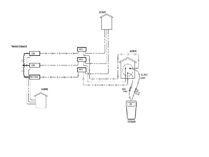
Procedure for Testing Service Connections/Cable 1. Pull meter base or leave meter base in, whichever is more convenient. 2. Attach alligator clips to either Hot leg / Neutral as shown in slide #10 and #11, only 3 connections are possible. 3. Push ON/OFF pushbutton IN to turn on ST 800. It is recommended, using the “V/I” pushbutton in the “V” (voltage) position, Line Voltages are verified on both Line-to-Line and Line-to-Neutral connections before proceeding. Note: Before removing alligator clips under possible load, turn OFF the ST 800 and then back ON after the connections have been made. 4. If any Voltage readings from Step #3 are not consistent with the System Voltage(s), identify which conductors are not terminated/connected and make necessary repairs before proceeding.
Procedure for Testing Service Connections/Cable 5. After Line-to-Line and Line-to-Neutral Voltages have been verified, using the “V/I” pushbutton in the “I” position, the current reading will display alternately with the number of counts until the service reaches 800 A or 158 counts (90 degrees). A good service should, under most conditions, achieve 800 Amps in less than 158 counts. Note: Extremely long (500 ft. >) and or small (#2) conductor good services may cause the ST 800 to NOT achieve 800 Amps because of too much Voltage Drop. It is up to each Utility to develop their own “Pass/Fail” criteria under these conditions.
ST 800 Connected Hot to Hot leg with Full Current Displayed
ST 800 Connected Hot to Neutral with Voltage Displayed
Procedure for Identifying Transformer Conductors 1. While the ST 800 is attached to Pedestal or Meter Base as shown in slide #13, it is pulsing a current on the conductors, note the Maximum current reading on the ST 800. 2. Adjust the STRCV Probe current selector switch to the respective current setting as displayed on the ST 800 in step #1. 3. Place the concave STRCV probe tip, as pointed out in slide #7, firmly against the outside of each jacket cable going into the X 1, X 2, X 3 terminals. 4. An Audible/Visual tone on only two conductors represents the cables to be identified as shown in slide #14, note direction of pulse and match from Step #1 for correct (hot(s) or neutral) identification.
Check for Identification away from close proximity from other conductors for a more consistent reading. The conductors in the left picture are too close, while the conductors in the right picture are much better with the conductors further apart.
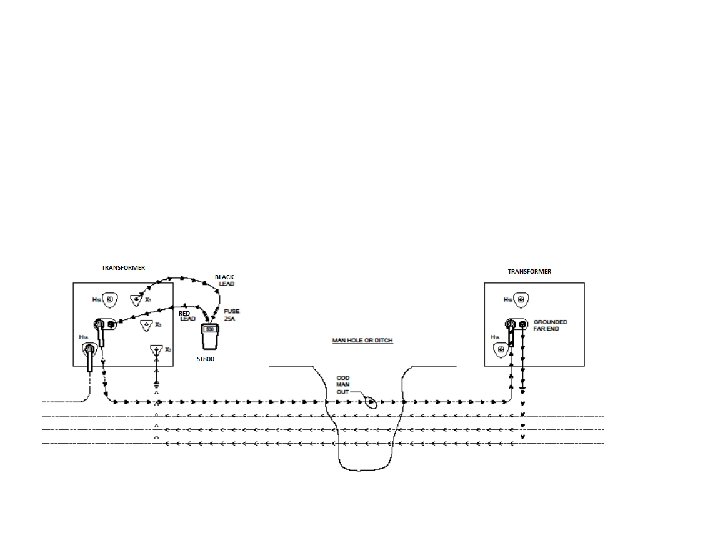
Procedure for Testing URD Primary Cable for De-energized • Isolate the URD Cable on near end and leave grounded on far end. • Test for de-energized cable on near end using Utility approved device before installing ST 800. • Connect ST 800 to hot leg (X 1 or X 3) of secondary and center conductor of de-energized grounded primary cable. • Using the STRCV probe at the open point, identify the de -energized cable via audible/visual tone. The deenergized cable will have an Audible/Visual tone in the opposite direction, as shown in slide #16, from the other conductors or the only Audible/Visual tone. Note: If no Audible/Visual tone is received from the STRCV, Bierer’s optional part# ACDM with the CT Clamp (part# Q 110) can be adjusted for more sensitivity.
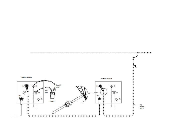
Testing IN/OUT Feed on Energized URD Primary Cable • Attach Black lead to X 1 hot leg bushing and Red lead to X 3 hot leg bushing as shown in slide #19. • Place the STRCV probe tip on each primary cable just below the elbow such that the cable rests in the concave section of the tip (as shown in slide #19) but not on the concentric neutral. An audible tone and a directional light will come on when the tip of the probe is on the cable being fed from the source. NOTE: The ST 800 can be installed and left at the end transformer. At the next transformer, the directional light pointing “up” (as shown in slide #18) into the transformer indicates the cable from the end transformer and the directional light pointing “down” (as shown in slide #18) out of the transformer indicates the cable going to the next transformer back to the source. This process can be repeated all the way back to the riser pole.
Continue “upstream” to find the line and load primary cable
Features • 9 V Battery power handheld device (<1 lbs) • Magnet for attaching to metal cabinets for hands free operation. • IP 67 rating for waterproof use. • Voltage range is 10 VAC - 500 VAC for testing very low voltage, three phase 277/480 customers, street light circuits, etc. • Easily identifies poor neutral, i. e. cable tv, telco bonds • Multipurpose device for quickly assessing power company vs customer issues, reduces RVM sets, identifies cables in the transformer, tests dead on URD primary circuits and identifies primary feed on transformers.