SRF RETRIEVAL USING AIRSIASI RADIANCES MANIK BALI NOAANESDISSTAR

SRF RETRIEVAL USING AIRS/IASI RADIANCES MANIK BALI NOAA/NESDIS/STAR

Contents • Introduction • Pre Vs Post Launch • Method • Steps • Simulations • Conclusions.

Introduction • Measurement accuracy of a detector critically depends on the accuracy of the detector’s Spectral Response Function (SRF). • Any shift or leaks in the SRF can dramatically influence the measured values and induce trends and biases in its measurements. ( eg AVHRR AATSR GOES-13) • It is important to monitor the status of in-orbit SRF while the instrument is

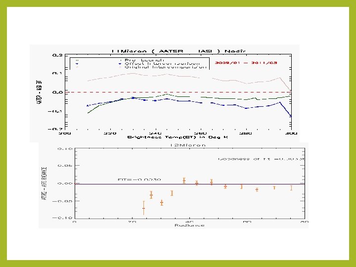
Pre Vs Post launch Offset= -0. 11 K < 0. 068 K < 0. 03 K Three years (2009 -2011) of AATSR/IASI collocation…. AIRS and IASI displays Pre-Launch like behavior in Space to a few 100 th of a degree. ATSR 2 and AATSR have SI traceable blackbodies. Since SRF was determined pre-launch so we can in principal determine SRF in space

Method Rep Rad = ---Convolution Hyperspectral Radiances AX=B SRF = A-1 B SRF Rep Radiances

Challenges • Bias has seasonal effects-does not always closely match with pre- launch. • In space, IASI itself has a offset, Question is how to bring target radiances to corrected radiances.
. 2. Apply")
Steps 1. Collect SNO collocations between target and reference ( Hyperspectral Instrument). 2. Apply GSICS recommended thresholds zenith, time, spatial homogeneity. 3. Convolute to find the Hyperspectral (IASI/AIRS/Cr. IS) Rep radiances. 4. Find a fit using a suitable polynomial 5. Find the fit to the pre-launch curve. 6. Apply the offset to get the ( so called) SI traceable radiances. 7. Perform the inversion using a suitable method like SVD.

Results LEO Instruments ATSR 2 and AATSR The retrieved SRF closely match the stated SRf Retrieved SRF from ATSR 2 appears less noisy.

Results GEO Instruments ATSR 2 and AATSR Results

Sensitivity of method to shifts and leaks

This leak gives the Red Curve Imagine there is a leak in the ATSR SRF and it looks like above Retrieved SRF using our method. Leak is clearly simulated.

Added a Shift of +4 WN

Blue is original SRF Black is SRF shifted by +4 WN The dots are the simulated SRF( analyzed in next slide) Impact on Radiances

Simulated SRF Original SRF Another way of measuring the Shift is to fit a known function to SRF at pre-launch and the SRF retrieved from our method Fit to the simulated SRF is blue. The fit to original SRF is red is the The shift is clearly visible in the fits to the SRF. The shift of the maxima is exactly of 4 WN.

Inputs The main input to this technique is a spectrum of radiances that are used as reference. Idea could be extended to non hyperspectrum Outputs The Spectral Response function.

Conclusions • De-Convolution is a promising technique that can be used to retrieve SRF status while the instrument is in orbit. • Hyperspectrum of AIRS and IASI can be used to retrieve SRF. • The method is sensitive to WN shifts as small as ± 4 WN. • The method can be applied to address SRF problems in VIIRS and GOES-13. • Work in progress…GOES Imager SRF for 13 Micron channel, use Cr. IS Spectrum and add uncertainty analysis.

Thank You
 IASI – AIRS 295 K (")
IASI – AIRS 210 K-230 K (using SNO) IASI – AIRS 295 K ( using GOES-11 Transfer) 11 Micron -0. 0790 (± 0. 06 ) RU -0. 0433(± 0. 016 ) RU 12 Micron -0. 1471 (± 0. 062) RU -0. 0460 (± 0. 018 ) RU Wang et al 2012
- Slides: 19