
SRF Materials Current Understanding and Future Direction Pashupati



- Slides: 37
SRF Materials: Current Understanding and Future Direction Pashupati Dhakal Monday, November 30, 2020
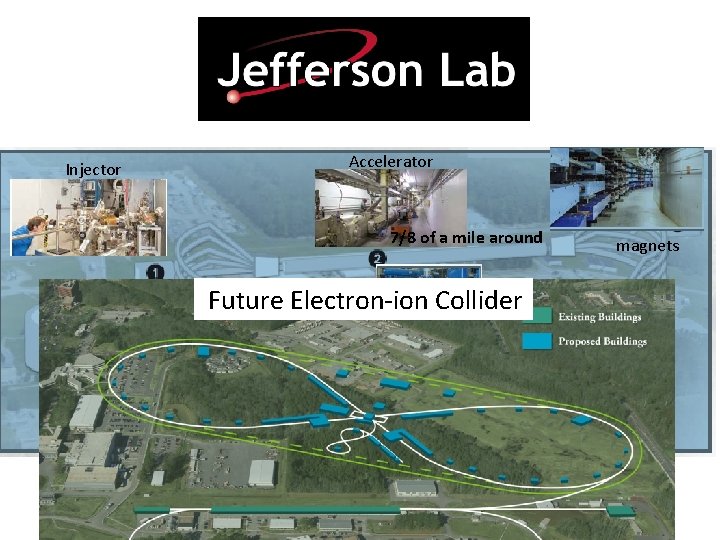
Injector Accelerator 7/8 of a mile around Cryoplant Future Electron-ion Collider Experimental Halls magnets
PARTICLE ACCELERATORS Electrostatic accelerators use static electric field to accelerate charge particles. Electromagnetic accelerators use changing electromagnetic field (magnetic or electric) to accelerator charge particles. About 30, 000 accelerators (small or big) around the world. Use in nuclear physics (atom smashers), radio therapy, ion implantations, biomedical research, high power lasers, etc. . 3
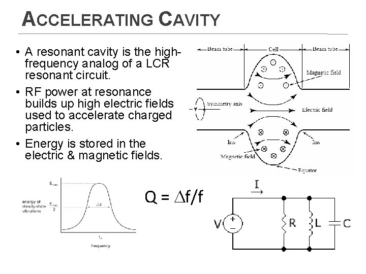
ACCELERATING CAVITY • A resonant cavity is the highfrequency analog of a LCR resonant circuit. • RF power at resonance builds up high electric fields used to accelerate charged particles. • Energy is stored in the electric & magnetic fields. Q = Df/f
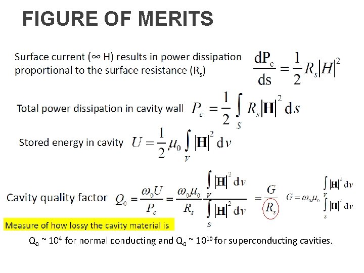
FIGURE OF MERITS Q 0 ~ 104 for normal conducting and Q 0 ~ 1010 for superconducting cavities.
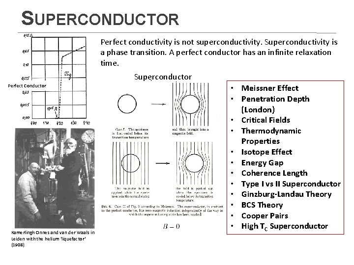
SUPERCONDUCTOR Perfect conductivity is not superconductivity. Superconductivity is a phase transition. A perfect conductor has an infinite relaxation time. Superconductor Perfect Conductor Kamerlingh Onnes and van der Waals in Leiden with the helium 'liquefactor' (1908) • Meissner Effect • Penetration Depth (London) • Critical Fields • Thermodynamic Properties • Isotope Effect • Energy Gap • Coherence Length • Type I vs II Superconductor • Ginzburg-Landau Theory • BCS Theory • Cooper Pairs • High TC Superconductor
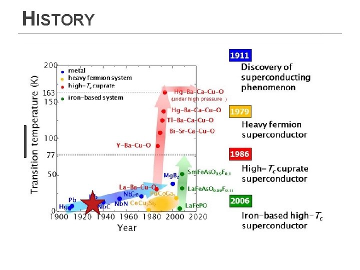
HISTORY
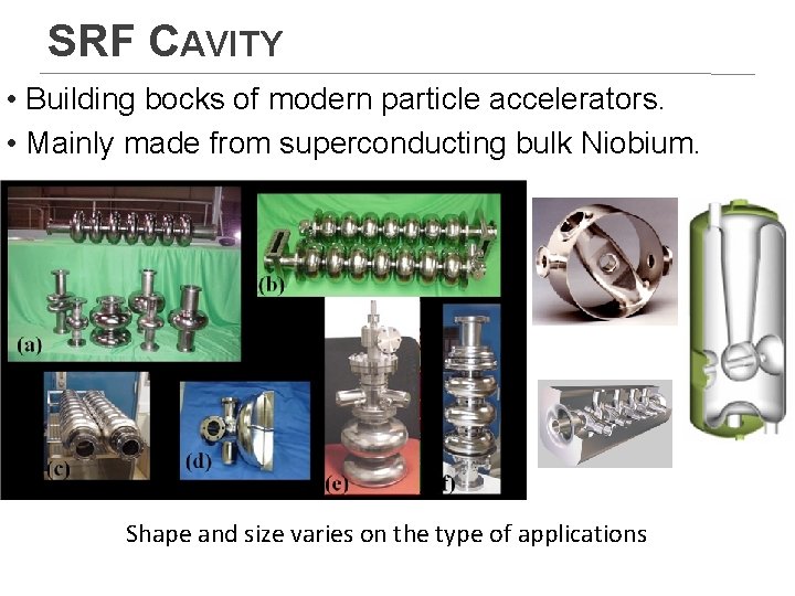
SRF CAVITY • Building bocks of modern particle accelerators. • Mainly made from superconducting bulk Niobium. Shape and size varies on the type of applications
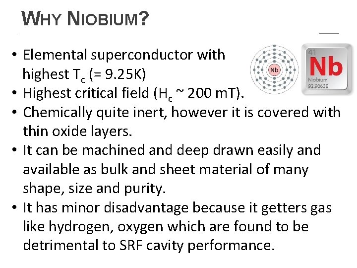
WHY NIOBIUM? • Elemental superconductor with highest Tc (= 9. 25 K) • Highest critical field (Hc ~ 200 m. T). • Chemically quite inert, however it is covered with thin oxide layers. • It can be machined and deep drawn easily and available as bulk and sheet material of many shape, size and purity. • It has minor disadvantage because it getters gas like hydrogen, oxygen which are found to be detrimental to SRF cavity performance.
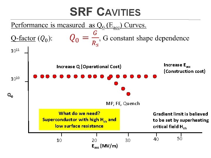
SRF CAVITIES 1011 Increase Eacc (Construction cost) Increase Q (Operational Cost) 1010 Q 0 MP, FE, Quench What do we need? Superconductor with high Hsh and low surface resistance 10 20 Eacc (MV/m) Gradient limit is believed to be set by superheating critical field Hsh 30 40 50
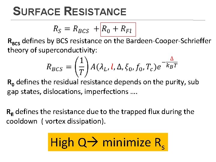
SURFACE RESISTANCE RBCS defines by BCS resistance on the Bardeen-Cooper-Schrieffer theory of superconductivity: R 0 defines the residual resistance depends on the purity, sub gap states, dislocations, imperfections …. Rfl defines the resistance due to the trapped flux during the cooldown ( vortex dissipation). High Q minimize Rs
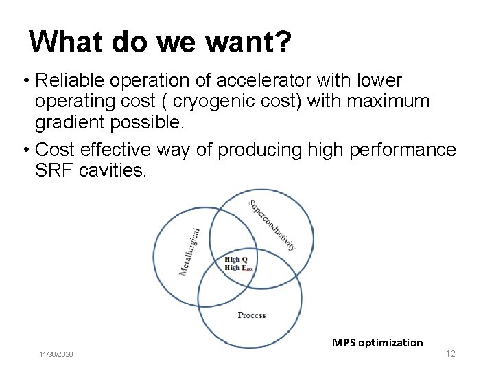
What do we want? • Reliable operation of accelerator with lower operating cost ( cryogenic cost) with maximum gradient possible. • Cost effective way of producing high performance SRF cavities. MPS optimization 11/30/2020 12
Material 11/30/2020 13
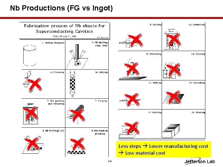
Nb Productions (FG vs Ingot) Less steps Lower manufacturing cost Low material cost 14
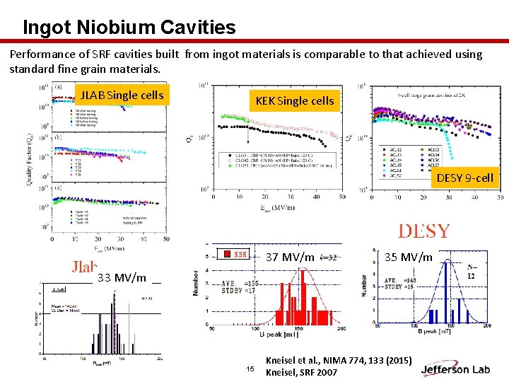
Ingot Niobium Cavities Performance of SRF cavities built from ingot materials is comparable to that achieved using standard fine grain materials. JLAB Single cells KEK Single cells DESY 9 -cell 37 MV/m 35 MV/m 33 MV/m 15 Kneisel et al. , NIMA 774, 133 (2015) Kneisel, SRF 2007
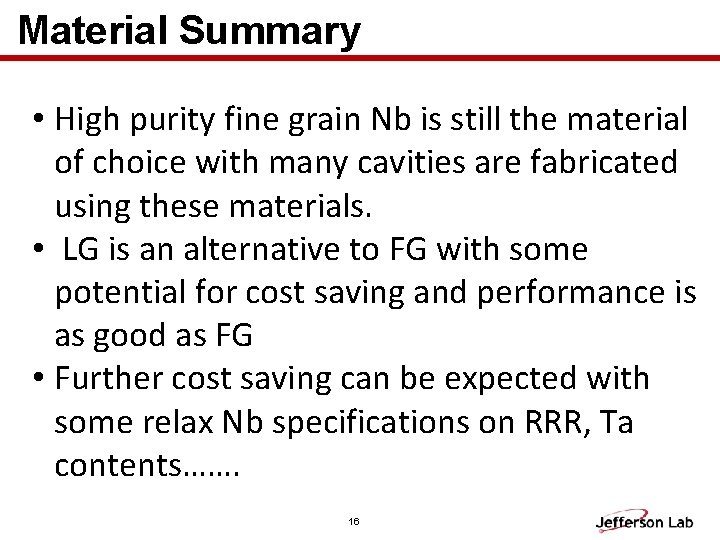
Material Summary • High purity fine grain Nb is still the material of choice with many cavities are fabricated using these materials. • LG is an alternative to FG with some potential for cost saving and performance is as good as FG • Further cost saving can be expected with some relax Nb specifications on RRR, Ta contents……. 16
Process 11/30/2020 17
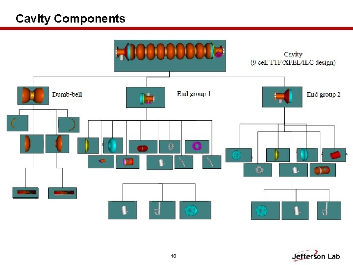
Cavity Components 18
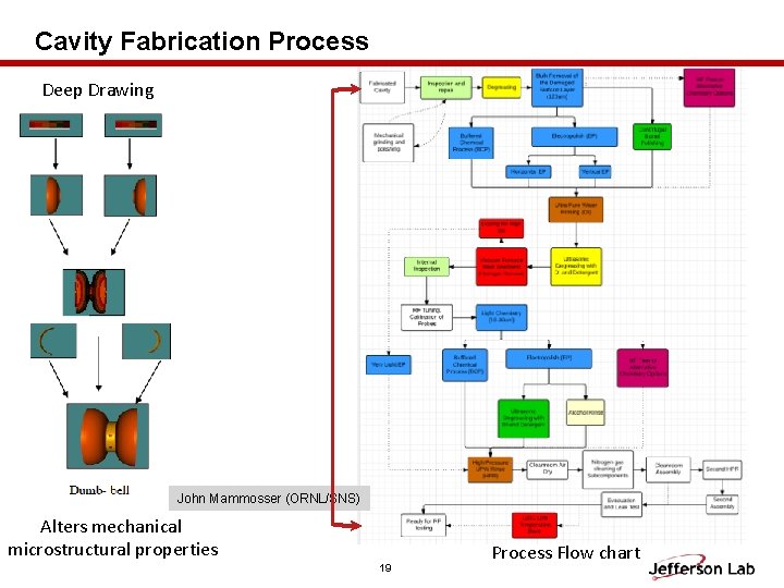
Cavity Fabrication Process Deep Drawing John Mammosser (ORNL/SNS) Alters mechanical microstructural properties 19 Process Flow chart
Process Summary • • Bulk surface removal (EP/BCP/CBP) Heat treatment ( degassing, mechanical stabilization) Doping (for high Q) Post heat treatment/doping surface removal High pressure rinse Clean room assembly RF test All of these process needed to be optimized for superior performance 20
SUPERCONDUTIVITY 11/30/2020 21
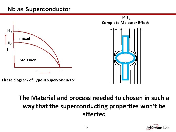
Nb as Superconductor T< Tc Complete Meissner Effect Hc 2 Hc 1 mixed H Meissner T Tc Phase diagram of Type-II superconductor The Material and process needed to chosen in such a way that the superconducting properties won’t be affected 22
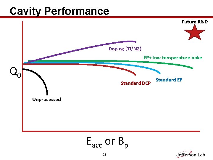
Cavity Performance Future R&D Doping (Ti/N 2) EP+ low temperature bake Q 0 Standard BCP Unprocessed Eacc or Bp 23 Standard EP
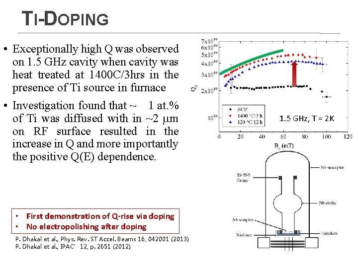
TI-DOPING • Exceptionally high Q was observed on 1. 5 GHz cavity when cavity was heat treated at 1400 C/3 hrs in the presence of Ti source in furnace • Investigation found that ~ 1 at. % of Ti was diffused with in ~2 mm on RF surface resulted in the increase in Q and more importantly the positive Q(E) dependence. • First demonstration of Q-rise via doping • No electropolishing after doping P. Dhakal et al. , Phys. Rev. ST Accel. Beams 16, 042001 (2013) P. Dhakal et al. , IPAC’ 12, p. 2651 (2012) 1. 5 GHz, T = 2 K
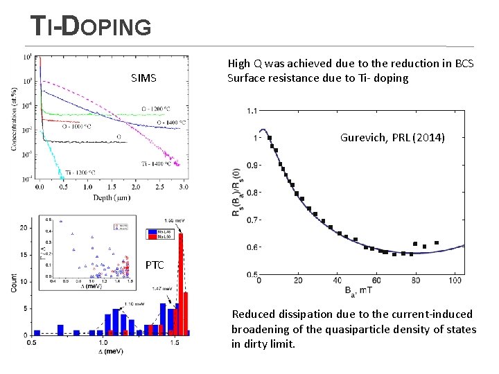
TI-DOPING SIMS High Q was achieved due to the reduction in BCS Surface resistance due to Ti- doping Gurevich, PRL (2014) PTC Reduced dissipation due to the current-induced broadening of the quasiparticle density of states in dirty limit.
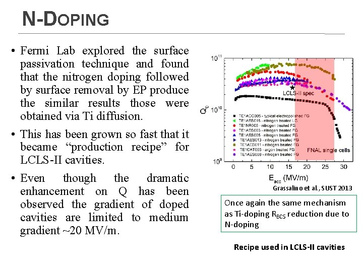
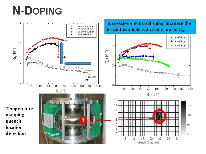
N-DOPING • Fermi Lab explored the surface passivation technique and found that the nitrogen doping followed by surface removal by EP produce the similar results those were obtained via Ti diffusion. • This has been grown so fast that it became “production recipe” for LCLS-II cavities. • Even though the dramatic enhancement on Q has been observed the gradient of doped cavities are limited to medium gradient ~20 MV/m. Grassalino et al. , SUST 2013 Once again the same mechanism as Ti-doping RBCS reduction due to N-doping Recipe used in LCLS-II cavities
N-DOPING Successive electropolishing increase the breakdown field with reduction in Q 0. Temperature mapping quench location detection
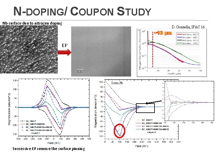
N-DOPING/ COUPON STUDY Nb-surface due to nitrogen doping EP Successive EP remove the surface pinning D. Gonnella, IPAC 16
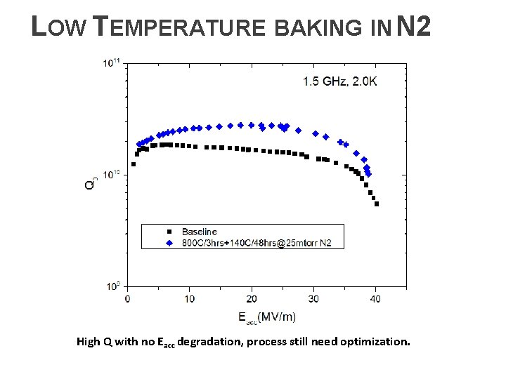
LOW TEMPERATURE BAKING IN N 2 High Q with no Eacc degradation, process still need optimization.
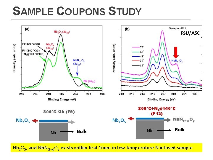
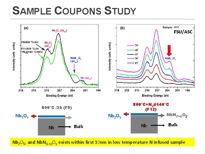
SAMPLE COUPONS STUDY FSU/ASC 800°C /3 h (F 9) Nb 2 O 5 Nb Bulk 800°C+N 2@140°C (F 12) Nb. N(1 -y)Oy Nb Bulk Nb 2 O 5, and Nb. N(1 -y)Oy exists within first 10 nm in low temperature N infused sample
SAMPLE COUPONS STUDY FSU/ASC 800°C /3 h (F 9) Nb 2 O 5 Nb Bulk 800°C+N 2@140°C (F 12) Nb. N(1 -y)Oy Nb Bulk Nb 2 O 5, and Nb. N(1 -y)Oy exists within first 10 nm in low temperature N infused sample
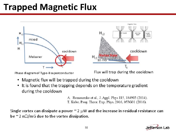
Trapped Magnetic Flux Single vortex can dissipate a power ~ 2 m. W and the increase in residual resistance can be ~ 2 n. W/m. G due to the vortex dissipation. 32
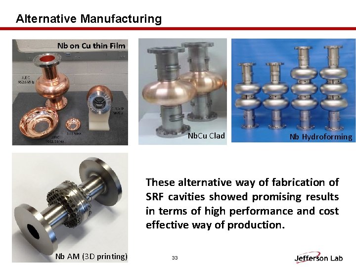
Alternative Manufacturing Nb on Cu thin Film Nb. Cu Clad Nb Hydroforming These alternative way of fabrication of SRF cavities showed promising results in terms of high performance and cost effective way of production. Nb AM (3 D printing) 33
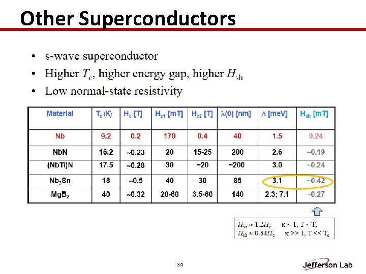
Other Superconductors 34
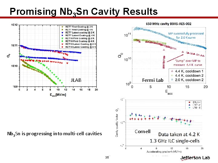
Promising Nb 3 Sn Cavity Results JLAB Fermi Lab Cornell Nb 3 Sn is progressing into multi-cell cavities 35
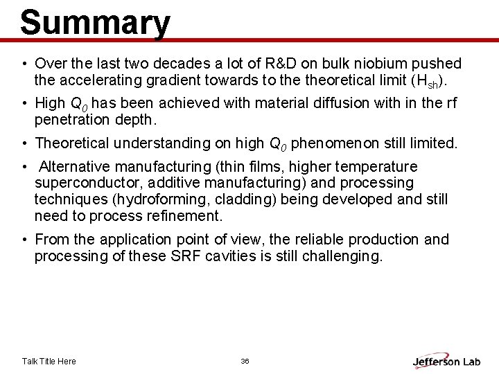
Summary • Over the last two decades a lot of R&D on bulk niobium pushed the accelerating gradient towards to theoretical limit (Hsh). • High Q 0 has been achieved with material diffusion with in the rf penetration depth. • Theoretical understanding on high Q 0 phenomenon still limited. • Alternative manufacturing (thin films, higher temperature superconductor, additive manufacturing) and processing techniques (hydroforming, cladding) being developed and still need to process refinement. • From the application point of view, the reliable production and processing of these SRF cavities is still challenging. Talk Title Here 36
37