
SR 1 extension follow up 03 Jul17 Marco
- Slides: 32
SR 1 extension follow up 03 -Jul-17 Marco Ciapetti
Introduction • • SMB matters Electrical matters Updated PBS Safety Coordinator Updated schedule Taken decision Things to be decided 2
SMB matters • SMB started the earthworks and networks deviation. This task will continue until the end of July. • The problem of the discovered unknown network is solved: – It was an old HV network, not any more under power. It has been removed – This cause 3 days of delay, but not on the critical path – The additional costs have been covered by the contingency • Drawing regarding the concrete are complete and the approval process has been started. You can find them on EDMS here • ECR have been approved on EDMS for the new external concrete slab (here) and for the new lateral opening (here) 3
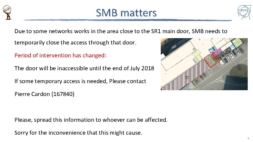
SMB matters Due to some networks in the area close to the SR 1 main door, SMB needs to temporarily close the access through that door. Period of intervention has changed: The door will be inaccessible until the end of July 2018 If some temporary access is needed, Please contact Pierre Cardon (167840) Please, spread this information to whoever can be affected. Sorry for the inconvenience that this might cause. 4
Electrical matters • Current 160 A switchboard should be replaced by a 250 A switchboard (maximum possible considering actual electrical consumption, future general needs and current transformer capacity). The extra cost will be around 6 k. CHF (agreed by TC). • According to Thierry (see email of 30/06/0217) a maximum of six 380 V-32 A sockets can be used simultaneously in exceptional cases: – 4 devices running on 380 V-32 A sockets can work at the same time with no constraints – It should be possible to add 2 more temporary • Grounding works will be done on week 28 and 29 (in agreement with SMB) 5
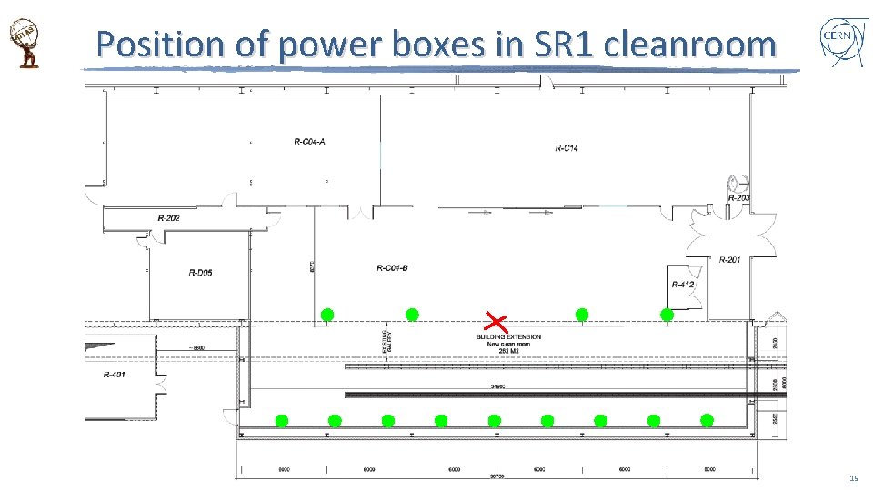
Electrical matters • 13 power boxes will be installed by EN/EL. One power box at each of the 4 pillars between existing room and extension (the central pillar will be removed) and one power box every 3 -4 m on the wall (evenly distributed). Each power box shall have at least: – 4 x 220 V - 16 A (CH standard) – 1 x 400 V - 32 A – Local differential switch for each sockets group (one for 4 sockets 230 V-16 A and one for socket 400 V-32 A) • 2 existing sockets boxes will be kept on UPS network (in the pillars area). No additional sockets on UPS network are required • Existing UPS network details: 100 k. VA lasting approx 10 minutes at 80 k. W (see email from Thierry sent on 28/06/2017) • Lighting will provide the same illumination of the actual clean room (≈400 lux) – Type of lights: LED (to minimize the maintenance) 6
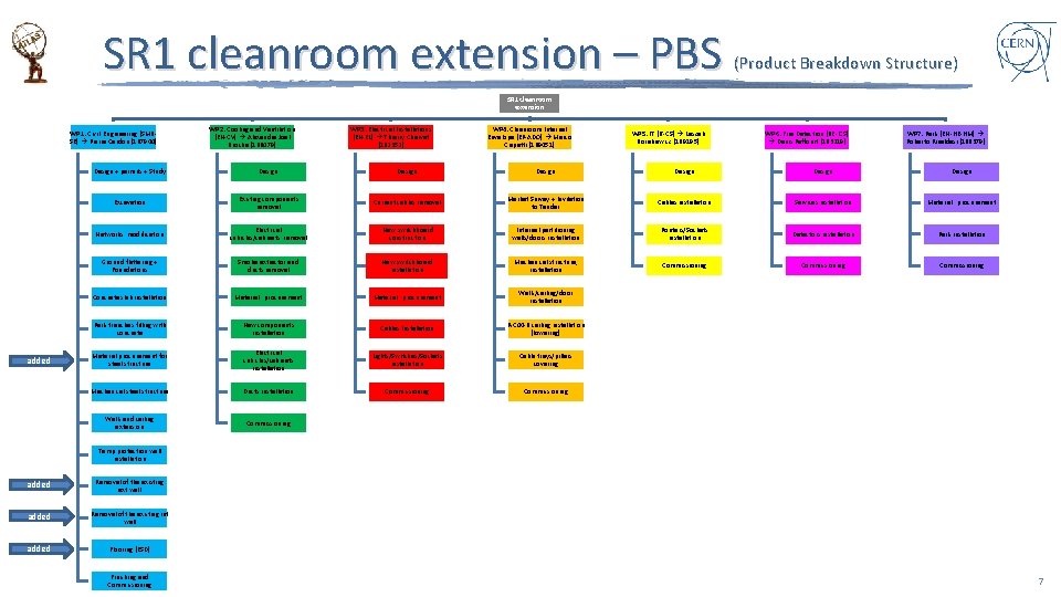
SR 1 cleanroom extension – PBS (Product Breakdown Structure) SR 1 cleanroom extension WP 1: Civil Engineering (SMBWP 1 SE) Pierre Cardon (167840) added WP 2: Cooling and Ventilation WP 2 (EN-CV) Alexandre Joel Broche (166078) WP 3: Electrical Installations WP 3 (EN-EL) Thierry Charvet (162352) WP 4: Cleanroom Internal WP 4 Envelope (EP-ADO) Marco Ciapetti (169451) WP 5: IT (IT-CS) Leszek WP 5 Borakiewicz (169195) WP 6: Fire Detection (BE-ICS) WP 6 Denis Raffourt (163219) WP 7: Rails (EN-HE-HM) WP 7 Roberto Rinaldesi (166379) Design + permits + Study Design Design Excavation Existing components removal Current cables removal Market Survey + Invitation to Tender Cables installation Services installation Material procurement Networks modification Electrical cubicles/cabinets removal New switchboard construction Internal partitioning walls/doors installation Routers/Sockets installation Detectors installation Rails installation Ground flattering + Foundations Smoke extractor and ducts removal New switchboard installation Mechanical structure, installation Commissioning Concrete slab installation Material procurement Walls/ceiling/door installation Rails trenches filling with concrete New components installation Cables Installation R-C 04 -B ceiling installation (lowering) Material procurement for steel structure Electrical cubicles/cabinets installation Lights/Switches/Sockets installation Cable trays/pillars covering Mechanical steel structure Ducts installation Commissioning Walls and ceiling extension Commissioning Temp protection wall installation added Removal of the existing ext wall added Removal of the existing int wall added Flooring (ESD) Finishing and Commissioning 7
Safety coordinator John Robert Etheridge John. Etheridge@cern. ch (164647) is the safety coordinator of P 1. He will help TC to ensure that all the works will be done according to the CERN safety rules. For all WPs, a VIC shall be prepared after the design phase and presented by the responsible of each WP to the safety coordinator before starting the works. John is invited to this follow-up meeting so that he can be informed about on-going activities and can control that all foreseen/incoming activities are properly planned from the safety point of view. 8
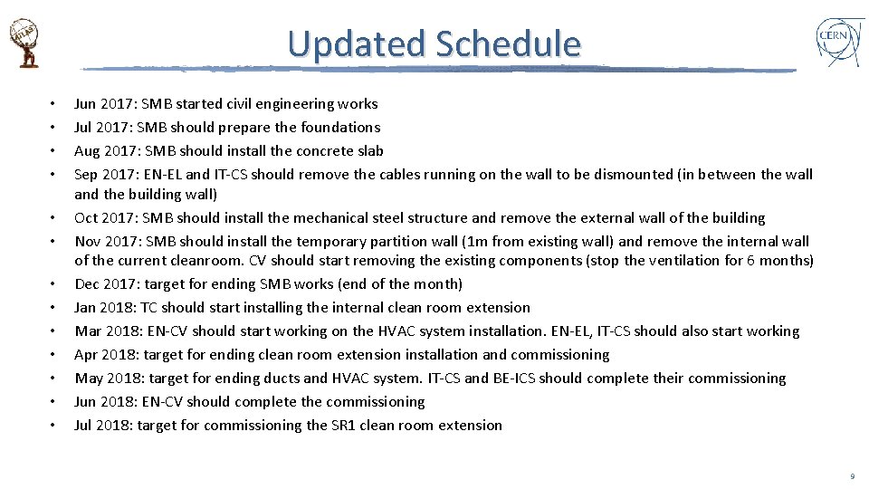
Updated Schedule • • • • Jun 2017: SMB started civil engineering works Jul 2017: SMB should prepare the foundations Aug 2017: SMB should install the concrete slab Sep 2017: EN-EL and IT-CS should remove the cables running on the wall to be dismounted (in between the wall and the building wall) Oct 2017: SMB should install the mechanical steel structure and remove the external wall of the building Nov 2017: SMB should install the temporary partition wall (1 m from existing wall) and remove the internal wall of the current cleanroom. CV should start removing the existing components (stop the ventilation for 6 months) Dec 2017: target for ending SMB works (end of the month) Jan 2018: TC should start installing the internal clean room extension Mar 2018: EN-CV should start working on the HVAC system installation. EN-EL, IT-CS should also start working Apr 2018: target for ending clean room extension installation and commissioning May 2018: target for ending ducts and HVAC system. IT-CS and BE-ICS should complete their commissioning Jun 2018: EN-CV should complete the commissioning Jul 2018: target for commissioning the SR 1 clean room extension 9
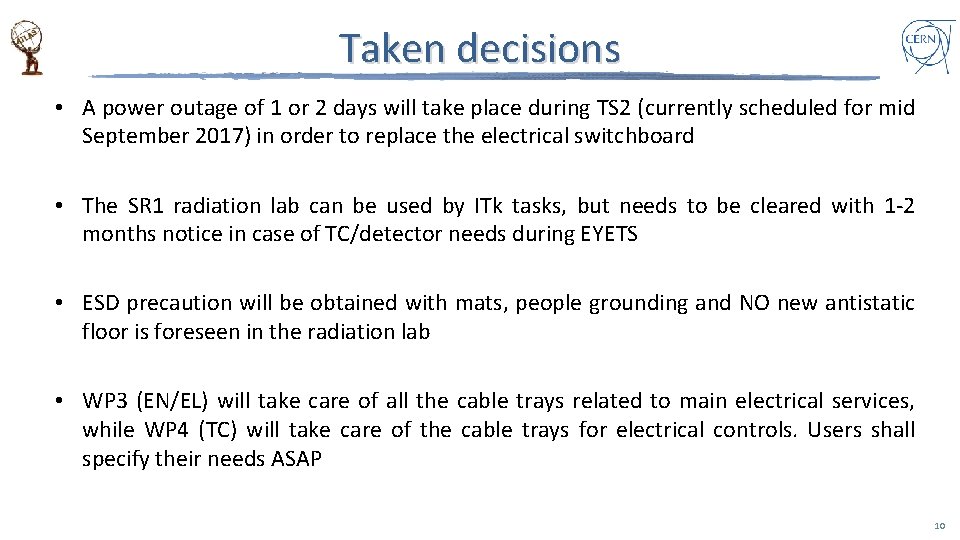
Taken decisions • A power outage of 1 or 2 days will take place during TS 2 (currently scheduled for mid September 2017) in order to replace the electrical switchboard • The SR 1 radiation lab can be used by ITk tasks, but needs to be cleared with 1 -2 months notice in case of TC/detector needs during EYETS • ESD precaution will be obtained with mats, people grounding and NO new antistatic floor is foreseen in the radiation lab • WP 3 (EN/EL) will take care of all the cable trays related to main electrical services, while WP 4 (TC) will take care of the cable trays for electrical controls. Users shall specify their needs ASAP 10
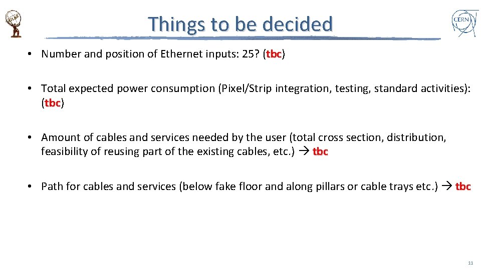
Things to be decided • Number and position of Ethernet inputs: 25? (tbc) tbc • Total expected power consumption (Pixel/Strip integration, testing, standard activities): (tbc) tbc • Amount of cables and services needed by the user (total cross section, distribution, feasibility of reusing part of the existing cables, etc. ) tbc • Path for cables and services (below fake floor and along pillars or cable trays etc. ) tbc 11
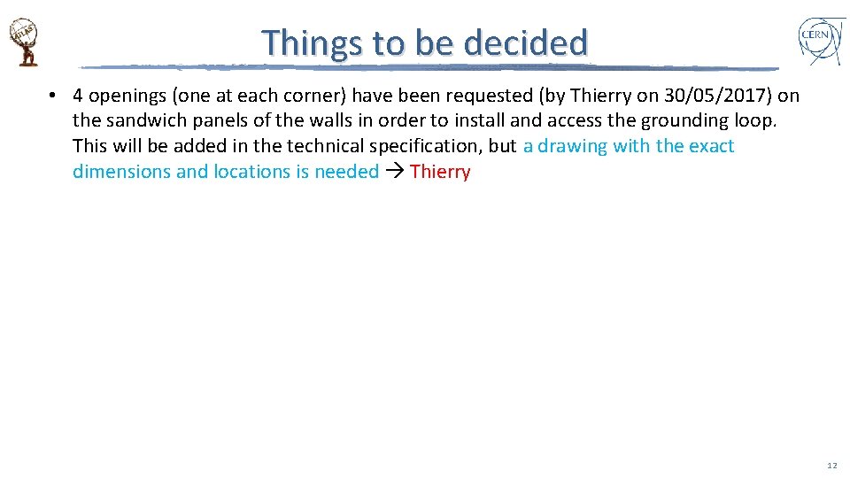
Things to be decided • 4 openings (one at each corner) have been requested (by Thierry on 30/05/2017) on the sandwich panels of the walls in order to install and access the grounding loop. This will be added in the technical specification, but a drawing with the exact dimensions and locations is needed Thierry 12
BACK UP SLIDES
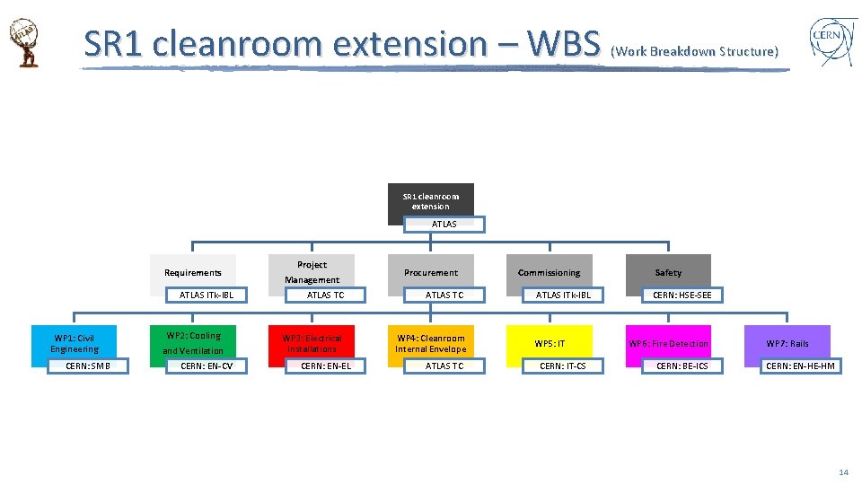
SR 1 cleanroom extension – WBS (Work Breakdown Structure) SR 1 cleanroom extension ATLAS Requirements ATLAS ITk-IBL WP 1: Civil Engineering CERN: SMB WP 2: Cooling and Ventilation CERN: EN-CV Project Management ATLAS TC WP 3: Electrical Installations CERN: EN-EL Procurement ATLAS TC WP 4: Cleanroom Internal Envelope ATLAS TC Commissioning ATLAS ITk-IBL WP 5: IT CERN: IT-CS Safety CERN: HSE-SEE WP 6: Fire Detection CERN: BE-ICS WP 7: Rails CERN: EN-HE-HM 14
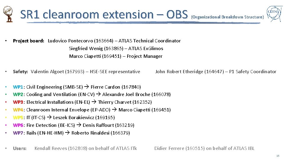
SR 1 cleanroom extension – OBS (Organizational Breakdown Structure) • Project board: Ludovico Pontecorvo (163664) – ATLAS Technical Coordinator Siegfried Wenig (163865) – ATLAS Ex. Glimos Marco Ciapetti (169451) – Project Manager • Safety: Valentin Algoet (167993) – HSE-SEE representative Safety: • • WP 1: Civil Engineering (SMB-SE) Pierre Cardon (167840) WP 1 WP 2: Cooling and Ventilation (EN-CV) Alexandre Joel Broche (166078) WP 2 WP 3: Electrical Installations (EN-EL) Thierry Charvet (162352) WP 3 WP 4: Cleanroom Internal Envelope (EP-ADO) Marco Ciapetti (169451) WP 4 WP 5: IT (IT-CS) Leszek Borakiewicz (169195) WP 5 WP 6: Fire Detection (BE-ICS) Denis Raffourt (163219) WP 6 WP 7: Rails (EN-HE-HM) Roberto Rinaldesi (166379) WP 7 • Users: Kendall Reeves (162808) on behalf of ATLAS ITk John Robert Etheridge (164647) – P 1 Safety Coordinator Didier Ferrere (160515) on behalf of ATLAS IBL 15
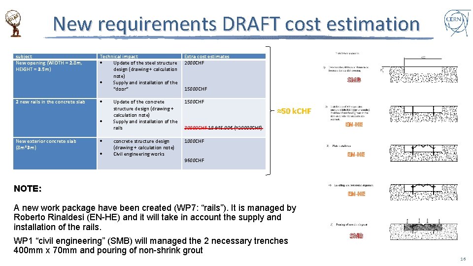
New requirements DRAFT cost estimation subject New opening (WIDTH = 2. 8 m, HEIGHT = 3. 5 m) 2 new rails in the concrete slab Technical impact Update of the steel structure design (drawing + calculation note) Supply and installation of the “door” New exterior concrete slab (8 m*3 m) Update of the concrete structure design (drawing + calculation note) Supply and installation of the rails concrete structure design (drawing + calculation note) Civil engineering works Extra cost estimates 2000 CHF 1500 CHF 30000 CHF 18 945. 00€ (≈20000 CHF) SMB ≈50 k. CHF 1000 CHF 9600 CHF NOTE: A new work package have been created (WP 7: “rails”). It is managed by Roberto Rinaldesi (EN-HE) and it will take in account the supply and installation of the rails. WP 1 “civil engineering” (SMB) will managed the 2 necessary trenches 400 mm x 70 mm and pouring of non-shrink grout SMB 16
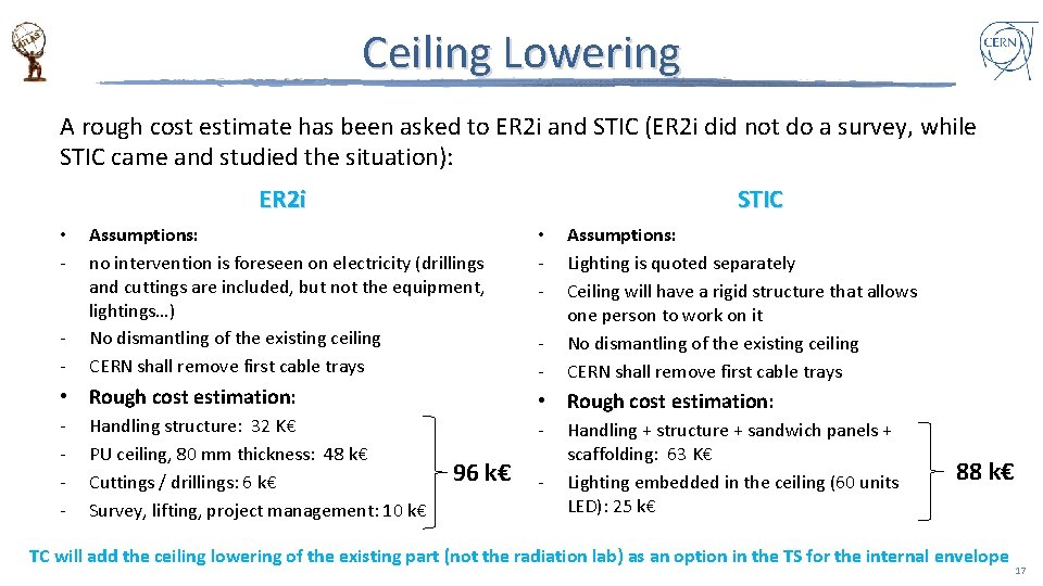
Ceiling Lowering A rough cost estimate has been asked to ER 2 i and STIC (ER 2 i did not do a survey, while STIC came and studied the situation): ER 2 i • - - STIC Assumptions: no intervention is foreseen on electricity (drillings and cuttings are included, but not the equipment, lightings…) No dismantling of the existing ceiling CERN shall remove first cable trays • Rough cost estimation: - Handling structure: 32 K€ PU ceiling, 80 mm thickness: 48 k€ Cuttings / drillings: 6 k€ Survey, lifting, project management: 10 k€ • - Assumptions: Lighting is quoted separately Ceiling will have a rigid structure that allows one person to work on it No dismantling of the existing ceiling CERN shall remove first cable trays • Rough cost estimation: - 96 k€ - Handling + structure + sandwich panels + scaffolding: 63 K€ Lighting embedded in the ceiling (60 units LED): 25 k€ 88 k€ TC will add the ceiling lowering of the existing part (not the radiation lab) as an option in the TS for the internal envelope 17
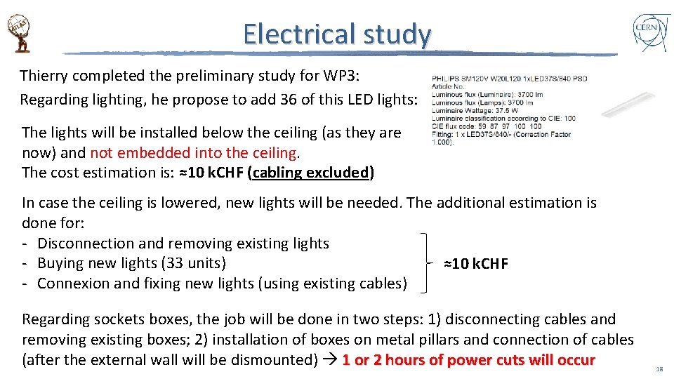
Electrical study Thierry completed the preliminary study for WP 3: Regarding lighting, he propose to add 36 of this LED lights: The lights will be installed below the ceiling (as they are now) and not embedded into the ceiling. The cost estimation is: ≈10 k. CHF (cabling excluded) In case the ceiling is lowered, new lights will be needed. The additional estimation is done for: - Disconnection and removing existing lights - Buying new lights (33 units) ≈10 k. CHF - Connexion and fixing new lights (using existing cables) Regarding sockets boxes, the job will be done in two steps: 1) disconnecting cables and removing existing boxes; 2) installation of boxes on metal pillars and connection of cables (after the external wall will be dismounted) 1 or 2 hours of power cuts will occur 18
Position of power boxes in SR 1 cleanroom 19
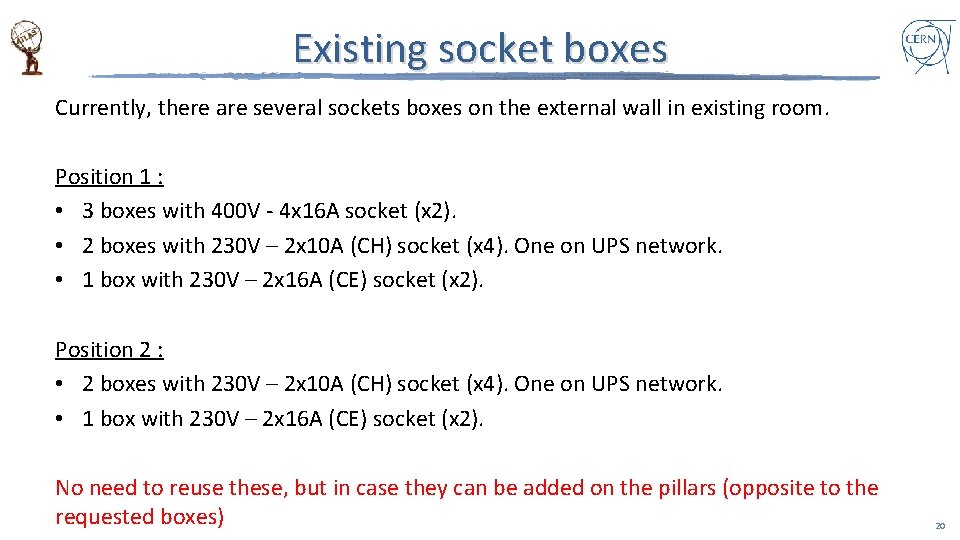
Existing socket boxes Currently, there are several sockets boxes on the external wall in existing room. Position 1 : • 3 boxes with 400 V - 4 x 16 A socket (x 2). • 2 boxes with 230 V – 2 x 10 A (CH) socket (x 4). One on UPS network. • 1 box with 230 V – 2 x 16 A (CE) socket (x 2). Position 2 : • 2 boxes with 230 V – 2 x 10 A (CH) socket (x 4). One on UPS network. • 1 box with 230 V – 2 x 16 A (CE) socket (x 2). No need to reuse these, but in case they can be added on the pillars (opposite to the requested boxes) 20
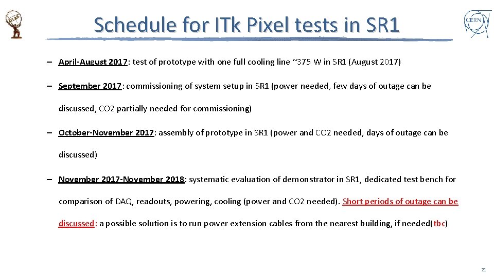
Schedule for ITk Pixel tests in SR 1 – April-August 2017: test of prototype with one full cooling line ~375 W in SR 1 (August 2017) – September 2017: commissioning of system setup in SR 1 (power needed, few days of outage can be discussed, CO 2 partially needed for commissioning) – October-November 2017: assembly of prototype in SR 1 (power and CO 2 needed, days of outage can be discussed) – November 2017 -November 2018: systematic evaluation of demonstrator in SR 1, dedicated test bench for comparison of DAQ, readouts, powering, cooling (power and CO 2 needed). Short periods of outage can be discussed: a possible solution is to run power extension cables from the nearest building, if needed(tbc) 21
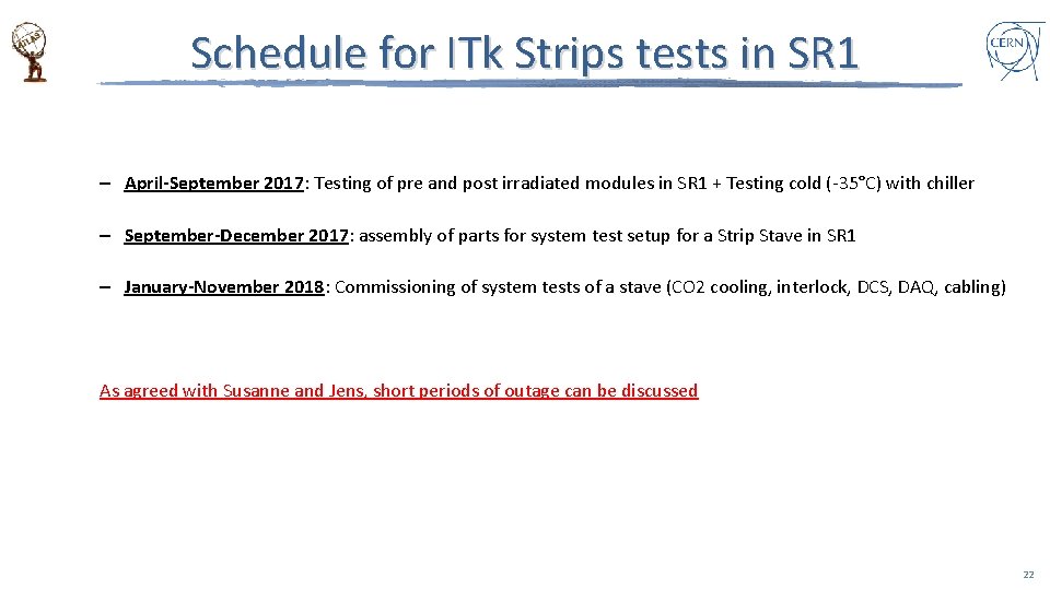
Schedule for ITk Strips tests in SR 1 – April-September 2017: Testing of pre and post irradiated modules in SR 1 + Testing cold (-35°C) with chiller – September-December 2017: assembly of parts for system test setup for a Strip Stave in SR 1 – January-November 2018: Commissioning of system tests of a stave (CO 2 cooling, interlock, DCS, DAQ, cabling) As agreed with Susanne and Jens, short periods of outage can be discussed 22
Taken decisions • The clean room will be ISO 8 according to ISO 14644 -1 • All cable trays shall be covered 23
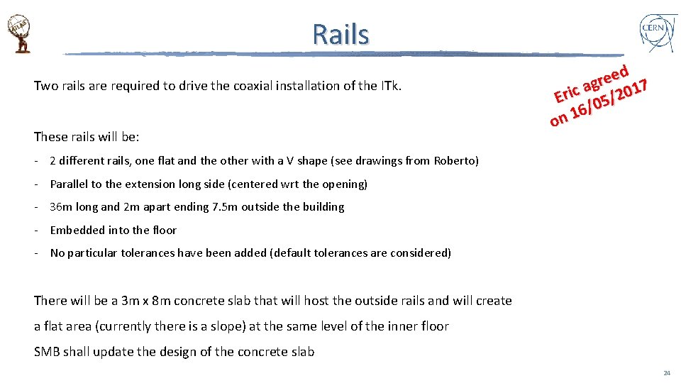
Rails Two rails are required to drive the coaxial installation of the ITk. These rails will be: d e e r g a 17 c 0 i r 2 E 5/ 0 / 6 1 n o - 2 different rails, one flat and the other with a V shape (see drawings from Roberto) - Parallel to the extension long side (centered wrt the opening) - 36 m long and 2 m apart ending 7. 5 m outside the building - Embedded into the floor - No particular tolerances have been added (default tolerances are considered) There will be a 3 m x 8 m concrete slab that will host the outside rails and will create a flat area (currently there is a slope) at the same level of the inner floor SMB shall update the design of the concrete slab 24
Opening on the short side An additional door has been required on the North-East-short-side wall of the extension, to ease the extraction of the ITk assembly. d e e r g a 17 c 0 i r 2 E 5/ 0 / 6 1 n o SMB will design an opening (2. 8 m wide and 3. 5 m high) centered in the N-E short side of the extension. This opening will be closed with a removable wall (not with an external door). This removable wall can be removed using a crane. The cleanroom will have a correspondent opening of the same dimensions and will present either an internal double door or another system to guarantee the sealing. 25
Taken decisions • EN-CV will switch off the air conditioning and ventilation for at least 6 months (schedule should meet SMB’s one) one • EN-EL will switch off the electricity for small periods of time (schedule should meet global schedule and users’ schedule) schedule • Overpressure targets: – Overpressure of extended clean room (R-C 04 -B) is ≥ 15 Pa – Overpressure of radiation lab (R-C 14) is ≥ 15 Pa – No overpressure in the test zone (R-C 04 -A), changing room (R-202), other areas – Overpressures of R-C 04 -B and R-C 14 can be manually regulated in order to create slight overpressure of the clean room over the radiation lab if needed 26
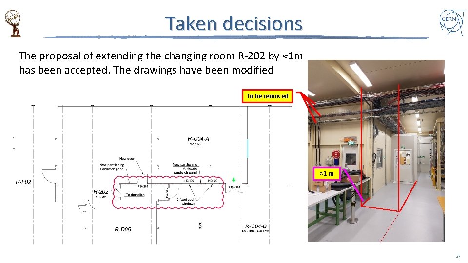
Taken decisions The proposal of extending the changing room R-202 by ≈1 m has been accepted. The drawings have been modified To be removed ≈1 m 27
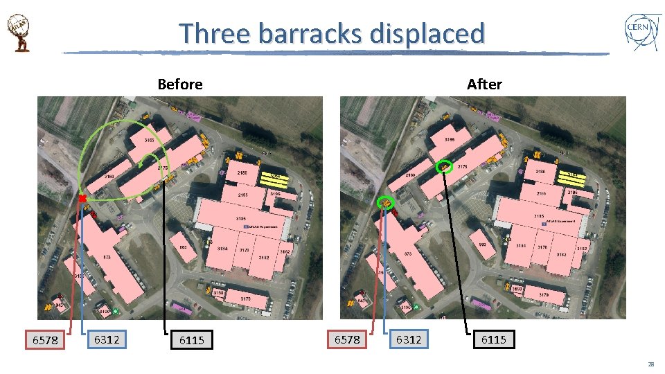
Three barracks displaced Before 6578 6312 6115 After 6578 6312 6115 28
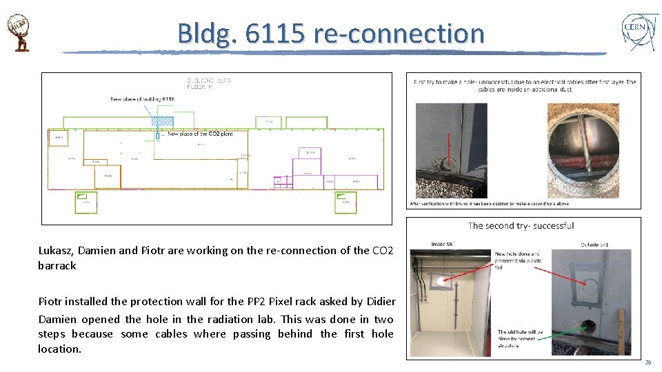
Bldg. 6115 re-connection Lukasz, Damien and Piotr are working on the re-connection of the CO 2 barrack Piotr installed the protection wall for the PP 2 Pixel rack asked by Didier Damien opened the hole in the radiation lab. This was done in two steps because some cables where passing behind the first hole location. 29
Cooling and Ventilation stop • The stop of CV system for at least 6 month announced by EN-CV and due to the replacement of the AHU and upgrade of the CV system will cause major problems in the ID test area • Didier, Anatoli and Dave agree that during such a long stop of the air conditioning, the test cannot be performed • A solution has been discussed among Didier, Alex and myself. It has been presented to all involved people and it has been agreed (see next slide) 30
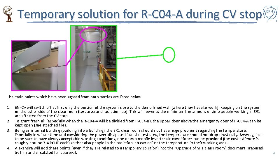
Temporary solution for R-C 04 -A during CV stop The main points which have been agreed from both parties are listed below: 1. EN-CV will switch off at first only the portion of the system close to the demolished wall (where they have to work), keeping on the system on the other side of the cleanroom (test area and radiation lab). This will lower at the minimum the amount of time people working in SR 1 are affected from the CV stop. 2. To grant fresh air (especially when the R-C 04 -A will be divided from R-C 04 -B), the upper door above the emergency door of R-C 04 -A can be kept open (see attached file). 3. Being an internal building (building into a building), the SR 1 cleanroom should not have huge problems regarding the temperature. Especially in winter time and considering the power dissipated into the test area, the temperature should not drop drastically. Anyway, just to be sure to have always acceptable working conditions, one or two mobile inverter air conditioner can be provided (the cost estimate is roughly around 3 -4 k. CHF each) so that also people in the radiation lab can adjust the temperature in their working area. 4. Alexandre will add these points (even if they are related to a temporary solution) into the “Upgrade of SR 1 clean room” document prepared by him and circulated for approval. 31
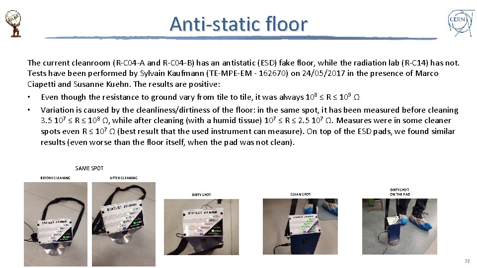
Anti-static floor The current cleanroom (R-C 04 -A and R-C 04 -B) has an antistatic (ESD) fake floor, while the radiation lab (R-C 14) has not. Tests have been performed by Sylvain Kaufmann (TE-MPE-EM - 162670) on 24/05/2017 in the presence of Marco Ciapetti and Susanne Kuehn. The results are positive: • Even though the resistance to ground vary from tile to tile, it was always 108 ≤ R ≤ 109 Ω • Variation is caused by the cleanliness/dirtiness of the floor: in the same spot, it has been measured before cleaning 3. 5 107 ≤ R ≤ 108 Ω, while after cleaning (with a humid tissue) 107 ≤ R ≤ 2. 5 107 Ω. Measures were in some cleaner spots even R ≤ 107 Ω (best result that the used instrument can measure). On top of the ESD pads, we found similar results (even worse than the floor itself, when the pad was not clean). SAME SPOT BEFORE CLEANING AFTER CLEANING DIRTY SPOT CLEAN SPOT DIRTY SPOT ON THE PAD 32