SPUR GEAR Introduction Gear can be defined as

SPUR GEAR Introduction- Gear can be defined as the mechanical element used for transmitting power and rotary motion from one shaft to another by means of progressive engagement of projections called teeth. Smaller of the pair is called pinion and the larger of the pair is called the gear.

ADVANTAGES OF GEAR DRIVES • 1 - Compact as compared to belt and chain drives. • 2 - Positive drives. • 3 - wide range of speed ratios. (6: 1 to 4900: 1) • 4 - High speed ratio than belt drives • 5 - Used for shafts parallel, intersecting, non-parallel, non-intersecting. • 6 - Large power transmission • 7 - Transmits power at higher speed.

LIMITATIONS OF GEAR DRIVES • • 1 - Costly. 2 - Can’t be used over a long distance. 3 - Requires precise alignment of shafts. 4 - Requires continuous lubrication.

CLASSIFICATION OF GEARS. • • • 1 - Parallel axis Gears. - Spur Gears. Helical Gears. Herringbone Gears. Rack and pinion. Internal gears. 2 - intersecting axis Gears- Bevel Gears. 3 - Non intersecting and Worm Gears perpendicular axis Gears 4 - Non intersecting and Crossed Non parallel axis Gears- Helical Gears

Parallel axis Gears SPUR GEAR

SPUR GEAR

Parallel axis Gears Helical gear

Parallel axis Gears Rack and pinion

Intersecting axis Gears- Bevel gear

Non-intersecting and perpendicular axis Gears-worm

WORM GEAR BOX

Non-intersecting, Non-parallel. CROSSED HELICAL GEAR

SELECTION OF TYPE OF GEARS • • • 1 - Relative position of Input and output shafts. 2 - Speed Ratio. 3 - Efficiency. 4 - Input speed. 5 - Power to be transmitted. 6 - Cost.

SPEED RATIO Sr. no Gear Drive Red. Ratio 1 Single stage spur/ Helical Gear 6: 1 2 Two stage spur or Helical gear 35: 1 3 Three stage spur or Helical gear 200: 1 4 Bevel gear drive 6: 1 5 Single stage worm gear 70: 1 6 Two stage worm gear 4900: 1

EFFICIENCY Sr. No. Gear Drive Efficiency 1 spur or Helical gear 96 -99% 2 Bevel gear drive 95 -98% 3 worm gear and worm wheel 45 -97%
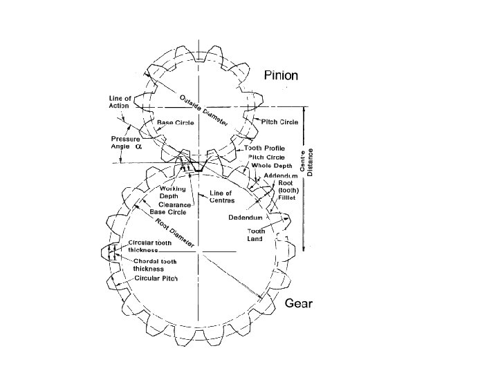

TERMINOLOGY IN SPUR GEAR

The common normal at the point of contact between a pair of teeth must always pass through the pitch point it is known as Law of gearing Law of Gearing

COMMON TERMINOLOGY • Pitch circle- It is an imaginary circle on gear which by pure rolling action would produce the same motion as the actual gear. • Pressure Angle- ( Ø) Angle between the common normal to the two meshing teeth at the point of contact and common tangent to the two pitch circles at the pitch point • Pitch Circle Dia. (d)- or PCD- It is the dia. of pitch circle. • Circular pitch- It is the dist. measured along the circumference of the pitch circle, from the point of one tooth to the corr. Point on the next tooth. z= No. of teeth.
- Ratio of PCD to the no. of teeth, •")
COMMON TERMINOLOGY • Module (m)- Ratio of PCD to the no. of teeth, • First choice- 1. 0, 1. 25, 1. 5, 2, 2. 5, 3, 4, 5, 6, 8, 10, 12, 16, 20, 25, 32, 40 and 50. • Second choice- 1. 125, 1. 375, 1. 75, 2. 25, 2. 75, 3. 5, 4. 5, 5. 5, 7, 9, 11, 14, 18, 22, 28. • Dimetral pitch (Pd)- Ratio of no. of teeth to PCD. • Speed Ratio(Gear Ratio)-G- Ratio of pinion speed to Gear speed
 : It is the distance betwwn the axes of the two")
Centre Distance (a) : It is the distance betwwn the axes of the two mating gears. It is given by Substituting in above equation Hunting Tooth: • In gear pair if gear ratio is an integer number like 1, 3/2, 4/3, same tooth on gear will come in contact with same tooth on pinion which increases the wear on teeth & reduce the life of teeth. • In such case extra tooth on the gear is added to spread the wear evenly. This extra tooth is called Hunting tooth.

INTERFERENCE The Phenomena when the tip of the tooth undercut the root on its mating gear is known as interference

MINIMUM NO. OF TEETH TO AVOID INTERFERENCE • The contact portions of the tooth profile which are not conjugate is called interference. • Interference is the meshing of two non-conjugate profiles. • Where ha= Addendum of meshing rack. m = module in mm. Ø= Pressure angle.

STANDARD SYSTEMS OF GEAR TOOTH • A tooth system is a standard which specifies the pressure angle and the relations for addendum, dedendum, working depth, tooth thickness and a fillet radius in terms of module. Objective- To attain interchangeability of gears of all tooth number but of the same pressure angle and module. • 1) 14. 5° composite system. • 2) 14. 5° full depth involute. • 3) 20° full depth involute. • 4) 22. 5° full depth involute. • 5) 20° stub tooth involute.

GEAR MATERIAL Desirable properties of gear material- • • Sufficient endurance strength in bending. Sufficient surface endurance strength. Low coefficient of friction. Low and consistent thermal distortion.
 Cast Iron. - Large size and complicated shapes")
TYPES OF GEAR MATERIALS • 1) Cast Iron. - Large size and complicated shapes Advantages of cast irons • Cheap • Good damping property • Good surface endurance strength but low bending endurance strength. • Graphite presents in C. I. works as lubricant. • Easily cast in complicated shapes • Good machinability Disadvantages of C. I. • Brittle, low bending strength.
 Steel • High bending endurance strength. • High")
TYPES OF GEAR MATERIALS • 2) Steel • High bending endurance strength. • High surface endurance strength. • Ductile • Expensive • Poor damping property. • Sensitive to thermal distortion during heat treatment. • Steel pinion and C. I. gear.
 Non- Ferrous metals- copper, Zink, tin, aluminum, bronze-")
TYPES OF GEAR MATERIALS • 3) Non- Ferrous metals- copper, Zink, tin, aluminum, bronze- worm gear. 4) Sintered Metalslow cost gears • 5) Non-metals. Bakelite, Nylon • Cheap, easy to manufacture, • Light weight, tolerate errors in tooth profile. • Do not have sufficient strength.

Force analysis of spur gears
 Tangential force Ft-Responsible for power transmission. • Ft=Tangential")
Force analysis of spur gears 1) Tangential force Ft-Responsible for power transmission. • Ft=Tangential force. • P= Power transmitted, W • V= Pitch line velocity, m/s • Tp= torque acting on pinion. • Tg= torque acting on Gear. • dp= P. C. D. of pinion. • dg= P. C. D. of Gear. • np= pinion speed, rpm. • ng= Gear speed, rpm. • Tangential force acting on the driving gear opposes the rotation of the driving gear whereas assists the rotation of driven gear.
 Radial Force- (Fr) Not useful component. • Tends")
Force analysis of spur gears 2) Radial Force- (Fr) Not useful component. • Tends to separate two gears. • Acts along the radial line through the pitch point and towards the centre. 3)Resultant force (F)=

GEAR TOOTH FAILURE • Gear tooth failure. . Wear failure or surface destruction Bending failure or breaking of tooth Pitting Initial Pitting Scoring Abrasive Wear Destructive Pitting Corrosive wear
 Bending failure or tooth breakage. • Gear tooth")
TYPES OF GEAR TOOTH FAILURE 1) Bending failure or tooth breakage. • Gear tooth is like a cantilever and subjected to repetitive bending stresses. • Tooth breakage happens when total load exceeds beam strength. • Avoided by adjusting module, face width, providing fillet radius. 2) Wear failure. Removes complete surface layer. • i) Pitting- Fatigue failure due to repetitive contact stresses. • A) Initial pitting- Because of high spots, surface irregularities, errors in tooth profile. It is a temporary phenomena. • Can be minimized by improving surface finish and proper alignment of gears.
 Destructive pitting- Due to repetitive contact stresses. • Depends upon Hertz contact stress,")
B) Destructive pitting- Due to repetitive contact stresses. • Depends upon Hertz contact stress, surface endurance strength, number of cycles. • Can be avoided by improving surface endurance strength. (Hardness). • Spalling-It is another surface fatigue failure in which the cracks originates below the gear tooth surface due to sub surface stresses. • Spalling can be avoided by providing sufficient case depth in surface hardening.

INITIAL PITTING

DESTRUCTIVE PITTING
 Metal to metal contact")
TYPES OF GEAR TOOH FAILURE ii Scoring- (scuffing or galling) Metal to metal contact due to lubrication failure. Excessive frictional heat and overheating of teeth. Welding and Tearing action. (stick-slip phenomena) iii Abrasive Wear. Damage caused by particles like dirt, dust in lubricant. Surface injury caused by particles trapped between mating teeth. Can be avoided by proper filtration of lubricant, use high viscosity oils, increasing surface hardness. iv Corrosive wear. Due to chemical action by improper lubricant, surrounding atmosphere.

INITIAL SCORING

MODERATE SCORING

DESTRUCTIVE SCORING

POLISHING WEAR

MODERATE WEAR

BEAM STRENGTH OF SPUR GEAR TOOTH Beam strength of the spur gear tooth is the maximum tangential load the gear tooth can take without tooth failure. Lewis Equation for Beam strength of spur Gear tooth Each tooth is considered as a cantilever beam fixed at the base. Radial force Fr- Induces a direct compressive stress of small magnitude and can be neglected. Tangential Force Ft- Induces a bending stress which tends to break the tooth.

F F F M = Max. bending moment at section BC = Ft. l Ft = tangential force acting on gear tooth l = Length of tool y = Half the thickness of the tooth t = Thickness of tooth section at b = Face width of the gear tooth I = 1. b. T 3 /12 Max. bending stress at pt. B

Max. bending stress at section BC From Equation tangential force acting on gear tooth The variables ‘t’ & ‘l’ depends upon the size of the gear tooth and its profile. Let t = K 1 pc and l= K 2 pc pc = Circular pitch K 1 , K 2 = Constants

Substitute the value in above equation we get Or y = Lewis form factor based on circular pitch Equation can be written as Y = Lewis form factor = When bending stress reaches the limiting value. The corresponding tangential force is called the beam strength = Bending endurance strength Fb = Beam strength of gear tooth Lewis equation for Spur gear

BEAM STRENGTH OF SPUR GEAR TOOTH

BEAM STRENGTH OF SPUR GEAR TOOTH

LEWIS FORM FACTOR The Lewis form factor Y is the function of tooth shape and the point of application of load. Lewis form factor depends upon 1) Number of teeth. 2) Tooth system. 3) Point of application of load. Y= 0. 484 - 2. 87/Z For 200 full-depth involute. Y= 0. 55 -2. 64/Z For 200 stub involute. Y= 0. 39 - 2. 15/Z For 14. 50 full depth involute and composite.

BENDING ENDURANCE STRENGTH The gear tooth is subjected to repeated bending stress. The bending endurance strength, σb = Ka. Kb. Kc. Kd. Ke. Kg. S’e (S’e= Endurance limit for test specimen) σb = Ka. Kb. Kc. Kd. Ke. Kg. x(0. 5 Sut). Where ka= surface finish factor Kb= size factor Kc= load factor Kd= temp. factor. Ke= Modifying factor for stress concentration. Kg= reliability factor.

BENDING ENDURANCE STRENGTH For Gears, Ka. Kb. Kc. Kd. Ke. Kg. . = 0. 66 σb = 0. 66 x 0. 5 Sut σb = 0. 33 Sut σb = Sut/3 Face Width- (b) Face width is taken between 9 to 15 times the module. (9 m to 15 m) Weaker of Gear or Pinion. The product (σb x Y) decides the weaker member. If (σb x Y) pinion < (σb x Y) gear, pinion is weaker in bending. When gear and pinion material is same, then Y is less for pinion and pinion is weaker.

WEAR STRENGTH OF SPUR GEAR TOOTH Wear strength of the Gear tooth is the maximum tangential load the gear tooth can take without pitting failure. Buckinghams equation for wear strength of a gear tooth. Wear strength, Fw= dp. b. Q. K • • dp = pitch circle diameter of pinion. b = face width of teeth. K= Load- stress factor Q= Ratio factor.

WEAR STRENGTH OF SPUR GEAR TOOTH σc = Surface indurance strength of weaker element. The expression for the ‘K’ can be simplified for different pinion & gear material and 200 pressure angle K= 0. 16 [BHN/100]2 N/mm 2 for steel pinion and steel gear. K= 0. 21 [BHN/100]2 N/mm 2 for C. I. pinion and steel gear. K= 0. 18 [BHN/100]2 N/mm 2 for steel pinion and C. I. gear.

EFFECTIVE LOAD ON SPUR GEAR TOOTH Effective load on the gear tooth is the total maximum tangential force acting on the gear tooth. Theoretical Tangential Force (Ft)- The theoretical tangential force acting on the gear tooth due to power transmission- • P= Power Transmitted in Watt • V= Pitch line velocity, m/sec. = (π d. n. / 60 x 1000) • Maximum Tangential Force-(Fmax. )Ft max. = Ka. Km. Ft • = Ka. Km. P/V • Application or Service factor (service factor/ overload factor) (Ka) • Load distribution factor (Load conc. Factor) (Km)-
 • • Accounts for increase in the tangential force due to")
Application factor- (Ka) • • Accounts for increase in the tangential force due to fluctuation of the torque by prime mover or load machine. It also known as service factor or overload factor. Varies from 1. 00 to 2. 5. Load distribution factor-( Km)Accounts for non-uniform distribution of load across the face width. Depends on. Alignment of gears. Bearing mounting. Gear tooth manufacturing accuracy.

Dynamic Load on Gear Tooth The tooth errors combined with the mass of the pinion and gear result in inertia forces. Additional forces arising out of the inertia effects are known as dynamic loads. Dynamic loads arises due to • Inaccuracies in tooth profile. • Errors in tooth profile. • Run out of the gear. • Inertia of the rotating masses. • Deflection of the teeth. • Stiffness of the rotating parts. Depends upon tooth error and pitch line velocity.

Dynamic Load on Gear Tooth

IS GEAR GRADES Based on the accuracy of gear tooth IS has classified the gears into twelve different grades IS Grade Accuracy level Manufacturin g Method Application Pitch line velocity 12 Very low Casting Low speed, Light load V≤ 10 m/s 10, 11 Low Hobbing Low speed V≤ 20 m/s 8, 9 Medium Fine hobbing Vehicle gears 20≤ V ≤ 25 6, 7 Medium, High Shaving, grinding Ind. gears 25≤ V ≤ 30 4, 5 High accuracy Shaving, finish grinding Turbine gears V > 30 1, 2, 3 Ultra high Finish grind, honing Master gears 40 ≤ V ≤ 200
Preliminary estimation by velocity factor. The effective load")
METHODS OF ESTIMATION OF DYNAMIC LOAD 1)Preliminary estimation by velocity factor. The effective load between the meshing teeth in tangential direction is given by Kv= Velocity factor-Barth factor. Depends upon gear accuracy and pitch line velocity.
 Precise Estimation by Buckinghams Equation. The Buckingham equation for the dynamic load in")
2) Precise Estimation by Buckinghams Equation. The Buckingham equation for the dynamic load in the tangential direction is given by Fd Ft max. Ft Ka Km V C = Dynamic load. = Maximum tangential force= Ka. Km. Ft =Tangential force = Application factor or service factor. = Load distribution factor or Load concentration Factor = Pitch line velocity. = Deformation factor or Dynamic factor.

Ep, Eg = modulii of elasticity for pinion & gear material. e K = sum of error on meshing teeth. =Tooth form factor. • Deformation factor( Dynamic factor) C- Depends upon the accuracy of gear teeth Steel pinion and steel gear-C = 11500 e N/mm C. I. pinion and C. I. gear- C = 8900 e N/mm. Steel pinion and C. I. gear- C = 10000 e N/mm Pitch errors on meshing teeth-(e)- Sum of pitch errors between two meshing teeth, mm. e =ep + eg ep = pitch error for pinion teeth, mm eg= pitch error for gear teeth, mm Depends upon gear grade, size, tooth size
 Safety against bending failure. Beam strength of the gear")
SAFETY OF GEAR PAIR 1) Safety against bending failure. Beam strength of the gear tooth ≥ Effective load. Fb ≥ Feff. Fb = F. S X Feff. 2) Safety against Wear Failure. Wear strength of the gear tooth ≥ Effective load. Fw ≥ Feff. Fw = F. S X Feff. Recommended factor of safety is 1. 5 to 2. It may extend up to 3

OBJECTIVES IN GEAR DESIGN • High power transmission. • Compact arrangement. • High efficiency. • Low initial cost. • Low maintenance and running cost. • Noise and vibration free operation.

DESIGN OF SPUR GEAR PAIR • Selection of tooth system. • Selection of the number of teeth. • Selection of material • Selection of gear grade. • Estimation of module, face width, pitch circle diameters, addenda and dedenda. The procedure for design of spur gear is as follows:

Start Input P, np, G Select Ø, Zp, Zg, Sup, Sug, BHN, Nf, Ka, Km & Gear Grade Calculate σbg, σbp. Yp, σbp. Yg, and σbg Yg Gear is weaker in Bending Calculate fb=σbp. b. Q. Yp In terms of ‘m’ Yes Is σbp. Yp< σbg. Yg No Gear is weaker in Bending Calculate fb=σbg. b. Q. Yg In terms of ‘m’

Calculate fw=dp. b. Q. K In terms of ‘m’ Calculate V = π m np Zp / 60 x 1000 In terms of ‘m’ Calculate Ft=P/V In terms of ‘m’ Calculate Kv In terms of ‘m’ Calculate feff = Ka Km ft / Kv In terms of ‘m’

Design based on Beam strength Is fb < f w Calculate fw=Nf. Feff Calculate ‘m’ by Trial & error Method Calculate fb=Nf. Feff Calculate ‘m’ by Trial & error Method 1) Increase m 2) Select strong material 3) Increase b 4) Increase accuracy of pinion & gear teeth Design based on Wear strength Select Next standard module ‘m’ Calculate dp, dg, b, ha, hf Calculate hf, fb, & fw 1) 2) 3) 4) Increase m Increase b Increase BHN Increase accuracy of pinion & gear teeth

Calculate fd by Buckingham’s equation Gear pair is unsafe against bending No Calculate feff = Ka Km ft + fd Yes No Is fb<fw Is fb>=Nf. feff Is fw>=Nf. feff Yes Gear pair is safe Stop Gear pair is unsafe against Pitting No
 Input- Power, Gear ratio, rpm of pinion.")
DESIGN OF SPUR GEAR PAIR • 1) Input- Power, Gear ratio, rpm of pinion. • 2) Select pressure angle (Ø), No. of teeth on pinion (zp) and gear(zg) , ultimate strength of pinion(Sup) and gear. Sug), surface hardness BHN), application factor(Ka), Load factor(Km). • 3) Calculate bending stress (σb), Lewis form factor (Y), product of (Lewis form factor x bending stress σbx. Y ). • 4) if it is less for pinion, pinion is weak. • 5) Calculate Beam strength Fb= σb. b. m. Y in terms of module. • 6) Calculate Wear strength Fw=dp. b. Q. K in terms of module.
Calculate pitch line velocity, V in terms")
DESIGN OF SPUR GEAR PAIR • • 7)Calculate pitch line velocity, V in terms of module. 8) Calculate tangential force, Ft= P/V. in terms of module 9) Calculate velocity factor, kv in terms of module. 10) Calculate effective load, Feff= ka. km. Ft/kv in terms of module. 11)If beam strength is less than wear strength, Design for beam strength. 12) Fb= Feff x f. s. 13) If wear strength is less than beam strength, Design for wear strength. Fw= Feff x f. s 14)Calculate m, dp, dg, b, ha, hf.
 Calculate Fd, Dynamic load by Buckinghams equation.")
DESIGN OF SPUR GEAR PAIR • 15) Calculate Fd, Dynamic load by Buckinghams equation. Fd=21 V(b. C+Ftmax. )/21 V+√b. C+Ftmax. • 16) Calculate Feff. = Ka. Km. Ft+Fd • 17) If Fb ≤ Fw and Fb ≥ Feff x. F. S, Gear pair is safe in bending. If not, gear pair is unsafe in bending. then increase next module, change material, increase accuracy. • 18) If Fw ≤Fb and Fw ≥ Feff x. F. S, Gear pair is safe in pitting. If not, gear pair is unsafe in pitting. Then increase next module, increase BHN, increase accuracy. • STOP.
 Given- m, Zp, Zg, b, ha,")
POWER TRANSMITTING CAPACITY OF SPUR GEAR • 0) Given- m, Zp, Zg, b, ha, hf, np, grade, Sup, Sug, BHN, Ka, Km, F. S. • 1)Decide weaker part in bending. • 2) Calculate bending strength based on step 1 • 3) Calculate Wear strength , Fw= dp. b. Q. K • 4) Calculate V (pitch line velocity), Kv(velocity factor) • 5)Calculate Feff. = Ka. Km. Ft/ Kv in terms of Ft. • 6) If Fb is less than Fw, power rating is based on Beam strength and if it is more than Fw, power rating is based on wear strength. • 7)Equating Fb or Fw with Feff x f. s, calculate Ft. • 8)P= Ft x V
 To reduce the possibility")
GEAR LUBRICATION • Objectives of gear lubrication • • 1) To reduce the possibility of scoring failure. 2) to reduce the wear of the teeth. 3) to reduce the power loss. 4) to act as coolant by dissipating heat. 4) to carry away the worn-out particles. 5) to minimise noise, vibration and shock. 6) to prevent corrosion.

LUBRICANTS USED IN GEARS. • • Grease. Straight mineral oil. Motor oil. - SAE Gear oils.

MODES OF LUBRICATION • • Grease lubrication. Drip-feed lubrication. Splash lubrication. Spray or jet lubrication.
 Splitting of reduction ratio by geometric progression. • 2)")
MULTI-STAGE GEAR REDUCER • 1) Splitting of reduction ratio by geometric progression. • 2) Splitting of reduction ratio for compact arrangement. - Higher reduction in earlier stages.
- Slides: 76