
SPS Crab Cavity test day 1 RF Test
SPS Crab Cavity test day 1 RF Test Program A (very) first look L. Arnaudon, P. Baudrenghien, R. Calaga, A. Macpherson, E. Montesinos (CERN) T. Mastoridis (Cal. Poly. State Univ. , San Luis Obispo, CA) On behalf of WP 4 The Hi. Lumi LHC Design Study is included in the High Luminosity LHC project and is partly funded by the European Commission within the Framework Programme 7 Capacities Specific Programme, Grant Agreement 284404.
Content • SPS layout vs. LHC layout • LHC CC operational scenario • Fast RF Controls loops • Slow RF controls loops • SPS test program CC-SPS day – Jan 2016 2
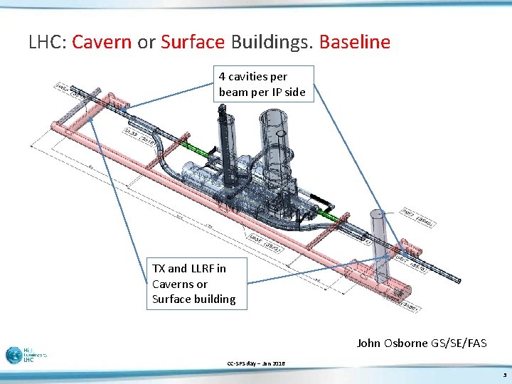
LHC: Cavern or Surface Buildings. Baseline 4 cavities per beam per IP side TX and LLRF in Caverns or Surface building TUNNEL John Osborne GS/SE/FAS CC-SPS day – Jan 2016 3
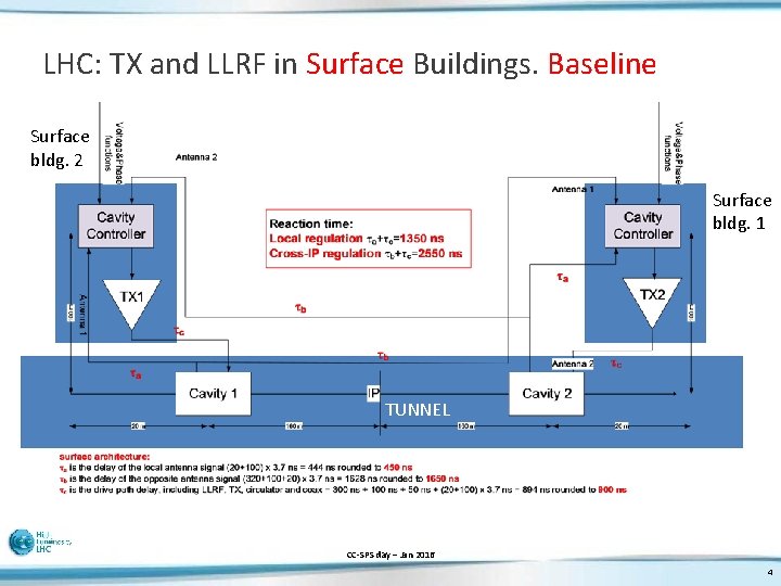
LHC: TX and LLRF in Surface Buildings. Baseline Surface bldg. 2 Surface bldg. 1 TUNNEL CC-SPS day – Jan 2016 4
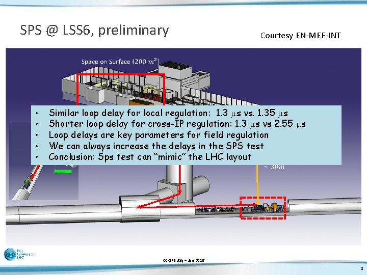
SPS @ LSS 6, preliminary Courtesy EN-MEF-INT • • • Similar loop delay for local regulation: 1. 3 ms vs. 1. 35 ms Shorter loop delay for cross-IP regulation: 1. 3 ms vs 2. 55 ms Loop delays are key parameters for field regulation We can always increase the delays in the SPS test Sps test can “mimic” the LHC layout Conclusion: CC-SPS day – Jan 2016 5
LHC CC Operational scenario • The RF is ON, with strong RF feedback and tune controls at all time. Cavities are on-tune at all time. • During filling, ramping or operation with transparent crab cavities: • Small cavity field as required for the active Tuning system • We use counter-phasing to make the total field invisible to the beam • A strong RF feedback keeps the Beam Induced Voltage zero if the beam is off-centred. • ON flat top: • We drive counter-phasing to zero • Any adiabatic field manipulation is possible by synchronously changing the voltage or phase in each cavity (luminosity levelling for example). CC-SPS day – Jan 2016 6
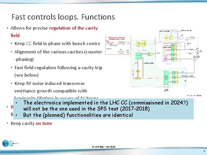
Fast controls loops. Functions • Allows for precise regulation of the cavity field • Keep CC field in phase with bunch centre • Alignment of the various cavities (counter -phasing) • Fast field regulation following a cavity trip (see below) • Keep RF noise induced transverse emittance growth compatible with luminosity lifetime in excess of 10 hours • The electronics implemented in the LHC CC (commissioned in 2024? ) • Reduction of cavity impedance at the will not be the one used in the SPS test (2017 -2018) fundamental • But the (planned) functionalities are identical • Keep cavity on tune CC-SPS day – Jan 2016 7
Coupled feedback • For perfect closure of the orbit and to minimize the overall effect of one-cavity fault, we look at the possibility of coupled feedback • Taking the two sets of cavities on each side of a given IP (crabbing and un-crabbing), we wish to keep the two total voltages equal • That can be done if the FDBK for a given TX considers also the voltage measured in all other cavities CC-SPS day – Jan 2016 8
LHC Fast Controls loops. Architecture • • • Only two cavities in the SPS Still we can develop/test Phase PU in SPS? tbd CC-SPS day – Jan 2016 9
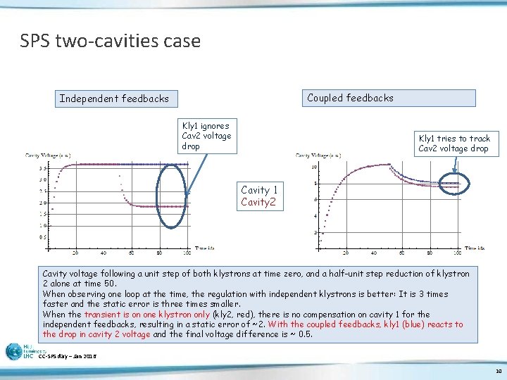
SPS two-cavities case Coupled feedbacks Independent feedbacks Kly 1 ignores Cav 2 voltage drop Kly 1 tries to track Cav 2 voltage drop Cavity 1 Cavity 2 Cavity voltage following a unit step of both klystrons at time zero, and a half-unit step reduction of klystron 2 alone at time 50. When observing one loop at the time, the regulation with independent klystrons is better: It is 3 times faster and the static error is three times smaller. When the transient is on one klystron only (kly 2, red), there is no compensation on cavity 1 for the independent feedbacks, resulting in a static error of ~2. With the coupled feedbacks, kly 1 (blue) reacts to the drop in cavity 2 voltage and the final voltage difference is ~ 0. 5. CC-SPS day – Jan 2016 10
Slow control and interlocks. Functions • Provide a standard infrastructure to control the RF power system • Provide interface with the external systems (cryo, vacuum, access, etc …) • Provide fast interlocks for protection • Implement the switch ON/OFF procedures for the RF power plant • Implement the local and Remote software interface for operation and for RF experts • Expose all relevant data to the CERN standard data acquisition, logging and alarms services. CC-SPS day – Jan 2016 11
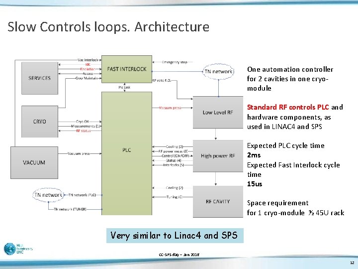
Slow Controls loops. Architecture One automation controller for 2 cavities in one cryomodule Standard RF controls PLC and hardware components, as used in LINAC 4 and SPS Expected PLC cycle time 2 ms Expected Fast Interlock cycle time 15 us Space requirement for 1 cryo-module ½ 45 U rack Very similar to Linac 4 and SPS CC-SPS day – Jan 2016 12
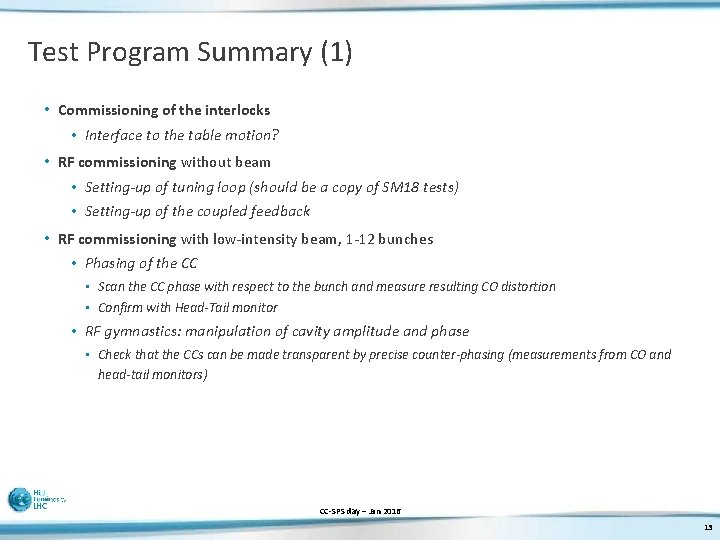
Test Program Summary (1) • Commissioning of the interlocks • Interface to the table motion? • RF commissioning without beam • Setting-up of tuning loop (should be a copy of SM 18 tests) • Setting-up of the coupled feedback • RF commissioning with low-intensity beam, 1 -12 bunches • Phasing of the CC • Scan the CC phase with respect to the bunch and measure resulting CO distortion • Confirm with Head-Tail monitor • RF gymnastics: manipulation of cavity amplitude and phase • Check that the CCs can be made transparent by precise counter-phasing (measurements from CO and head-tail monitors) CC-SPS day – Jan 2016 13
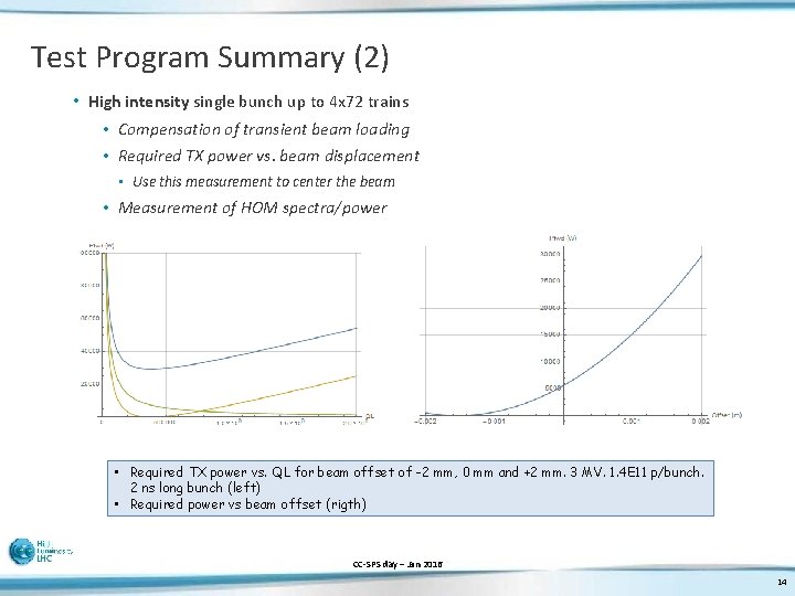
Test Program Summary (2) • High intensity single bunch up to 4 x 72 trains • Compensation of transient beam loading • Required TX power vs. beam displacement • Use this measurement to center the beam • Measurement of HOM spectra/power • Required TX power vs. QL for beam offset of -2 mm, 0 mm and +2 mm. 3 MV. 1. 4 E 11 p/bunch. 2 ns long bunch (left) • Required power vs beam offset (rigth) CC-SPS day – Jan 2016 14
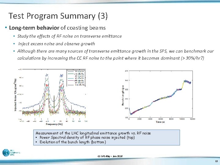
Test Program Summary (3) • Long-term behavior of coasting beams • Study the effects of RF noise on transverse emittance • Inject excess noise and observe growth • Although there are many sources of transverse emittance growth in the SPS, we can benchmark our calculations by increasing the CC RF noise to the point where it becomes dominant (> 30%/hr? ) Measurement of the LHC longitudinal emittance growth vs. RF noise • Power Spectral density of RF phase noise injected (top) • Evolution of the bunch length (bottom) CC-SPS day – Jan 2016 15
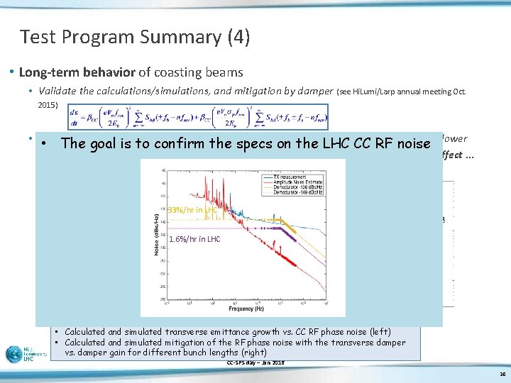
Test Program Summary (4) • Long-term behavior of coasting beams • Validate the calculations/simulations, and mitigation by damper (see Hi. Lumi/Larp annual meeting Oct. 2015) • The SPS CC emittance growth will be much larger than the final LHC system (noisy LLRF, lower • The goal is to confirm the specs on the LHC CC RF noise energy, smaller frev - but smaller bcc) -> probably no need to boost the noise to see an effect … 33%/hr in LHC 1. 6%/hr in LHC • Calculated and simulated transverse emittance growth vs. CC RF phase noise (left) • Calculated and simulated mitigation of the RF phase noise with the transverse damper vs. damper gain for different bunch lengths (right) CC-SPS day – Jan 2016 16
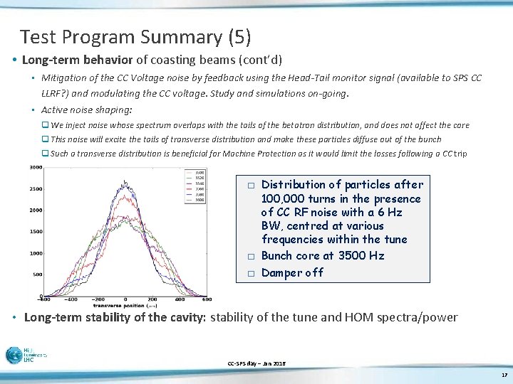
Test Program Summary (5) • Long-term behavior of coasting beams (cont’d) • Mitigation of the CC Voltage noise by feedback using the Head-Tail monitor signal (available to SPS CC LLRF? ) and modulating the CC voltage. Study and simulations on-going. • Active noise shaping: q We inject noise whose spectrum overlaps with the tails of the betatron distribution, and does not affect the core q This noise will excite the tails of transverse distribution and make these particles diffuse out of the bunch q Such a transverse distribution is beneficial for Machine Protection as it would limit the losses following a CC trip � � � Distribution of particles after 100, 000 turns in the presence of CC RF noise with a 6 Hz BW, centred at various frequencies within the tune Bunch core at 3500 Hz Damper off • Long-term stability of the cavity: stability of the tune and HOM spectra/power CC-SPS day – Jan 2016 17
Test Program Summary (6) • Field evolution following a fast failure. Case 1: • A problem with power hardware supplying one cavity (such as TX trip, arcing in waveguide, circulator or load, …) resulting in switching off the TX. The cavity stored energy will flow out, through the waveguide and circulator, and will be dissipated into the circulator’s load. The • cavity field will decay to zero with a time constant t Valuable lessons from the SM 18 tests • But experiment with beam is essential: • • Effect on the second cavity in same cryostat? Mitigation of the beam losses by the coupled-cavities feedback? • With a QL equal to 500000, the time constant is 400 ms. • Field evolution following a fast failure. Case 2: • In the case of a quench, the stored energy is dissipated in the cavity walls and the He. The main coupling (QL) has no effect on the field evolution. Lessons must be learnt from the SM 18 and SPS tests. • Field evolution following a fast failure. Case 3: • In the case of an arc in the main coupler, the stored energy will be dissipated through the arc. Again lessons must be learnt from the SM 18 and SPS tests. CC-SPS day – Jan 2016 18
Questions? Comments? CC-SPS day – Jan 2016 19
- Slides: 19