SPECIFICATIONS TESTING AND INSTALLATION OF NEOPRENE BEARINGS IRC
")
SPECIFICATIONS, TESTING AND INSTALLATION OF NEOPRENE BEARINGS IRC 83 (Part II)

Load range & movement in Bearings Type of bearing Steel sliding plates. Load Movement (TONNES) (mm) 20 -133 25 Roller bearing 60 -266 100 Elastomeric Bearing 30 -220 60 Pot bearing 20 -1780 No limit
 Remarks")
Suitability of Bearing for Steel spans Type of bearing Bridge & Spans (m) Remarks Both end steel plates. Plate girders 9. 15, 12. 2, 18. 3, 24. 4, 30. 5 Elastomeric on local conditions phosphor bronze Composite 9. 15, 12. 2, 18. 3, 24. 4, 30. 5 For U/S O/W - 30. 5 (With one end fixed) Rocker & Roller O/W through girders- 30. 5, One end fixed & other 45. 7(2 rollers), 61. 0, 76. 2 free (4 rollers) Rocker & Roller with oil bath O/W through girders more than 76. 2 POT PTFE bearings are being used for longer spans -do-

Suitability of Bearing for PSC spans Type of bearing Elastomeric Bearing Bridge & Spans Remarks (m) I section/ BOX As per Cl. 16. 9. 13 of Concrete Bridge Code, section girders Elastomeric bearings shall be restricted for clear spans more than 30. 5 m POT / PTFE bearing All PSC spans ≥ 30. 5 M Earthquake restraint shall be provided for longer spans

ELASTOMERIC BEARINGS • • Elastomer is aaformofofrubber, a class of polymeric Elastomer is a class of polymeric substance obtained after vulcanization. (makingrubber stronger and moreelasticby bytreatingwithsulphur stronger and at at high temperature) • • As resultof of vulcanization, rubber molecules As aaresult vulcanization, rubber molecules are cross linked with sulphur, making the rubber stronger • • It possesses rubber like properties i. e. ability to to regain It possesses shape almost completely even after large deformations • • These are veryflexibleininshearbut butvery stiff in bulk These are stiff in bulk compression • • Design as per. UIC 772 -2 R 1989 and Design as asas perper IRCIRC 83 83 Part II II

ELASTOMERIC BEARINGS • The behavior of elastomeric bearings 1. The elastomer being practically incompressible, the total volume of pad in loaded and unloaded condition remains unchanged. 2. Under action of compressive load , plain elastomeric pad with no friction on its top and bottom surface flattens and expands laterally 3. Frictionless contact surface does not exist in practice, so deformation will be partly bulging and flattening 4. By bonding the elastomer between two layers, the lateral expansion is prevented and bulging is controlled

Shape Factor • Compressive strength of the bearing depends upon the ratio of loaded area to the area of bearing free to bulge. This is known as Shape Factor “S” which is a dimensionless parameter • Greater compressive stiffness is , therefore, obtained by dividing elastomer in to many layers by introducing very thin, usually 1 to 3 mm steel reinforcement plates.

c c laminate b c l

ELASTOMERIC BEARINGS • The elastomeric bearings offer a number of advantages as listed below: 1. 2. 3. 4. 5. Minimum maintenance- as no moving parts Installation is easy Permits movement in all directions Occupies small space Serves as a shock absorber due to anti-vibrations properties of elastomer 6. As an aid to better management of longitudinal forces.

SHEAR/ TRANSLATION ACTION

ROTATION/ BENDING ACTION

ACTION UNDER VERTICAL LOAD • Vertical load gets converted to shear in the elastomer/ laminate interface
 FRANCE • Elastomer doesn’t")
IMPORTANT FINDINGS BY ORE (OFFICE FOR RESEARCH AND EXPERIMENT ) FRANCE • Elastomer doesn’t follow hook’s law & (Modulus of Elasticity) so E is not constant • But (Shear Modulus) G is Constant & G is more relevant for the design of elastomeric bearing than E • µ between elastomer & base material unaffected by nature of contact surface steel or concrete • µ reduces with increased normal loads(N) on the bearing expressed by µ=0. 1+0. 6/N

IMPORTANT FINDINGS BY ORE CONTD. • Performance of elastomer not affected by temp variation with in range of (-15 to +50 o. C) • Under cyclic load, bearing becomes more flexible • Tendency to slip, when normal pressure is less than 2 MPa. • In smaller bridges these bearings are used with anti creep devices
 • IRC 83 – Rectangular in plan – Internal layers")
NEOPRENE BEARINGS (912. 1) • IRC 83 – Rectangular in plan – Internal layers shall be of equal thickness – Bearings safeguarded against displacement by interface friction without the aid of adhesive or external anchoring device – No dowel holes in elastomer/ laminate, even when filled up subsequently
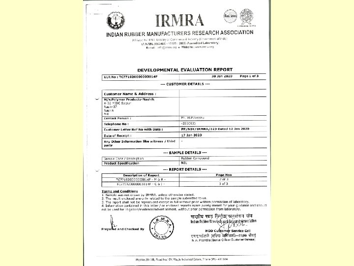
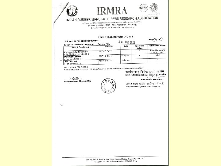
 • Polychloroprene (synthetic rubber) only shall be used (natural rubber-poly")
RAW MATERIAL (915. 1) • Polychloroprene (synthetic rubber) only shall be used (natural rubber-poly isoprene is highly reactive with ozone which causes surface cracks) • Reclaimed rubber or vulcanized wastes or natural rubber shall not be used • Polychloroprene content>60% • Ash content <5%
 • Neoprene WRT, Bayprene 110, Skyprene B-5 And Denka S-40")
RAW MATERIAL (915. 1) • Neoprene WRT, Bayprene 110, Skyprene B-5 And Denka S-40 V shall be used as elastomer • EPDM (Ethyl Propylene Dimonomer) shall not be used – Infrared spectrography shall be done for polymer identification , as per ASTM D 3677
 Property Test method I. S. Specification reference Value specified")
PROPERTIES OF ELASTOMER (915. 2) Property Test method I. S. Specification reference Value specified / Permissible limits 1. Physical Properties : 1. 1 Hardness* 1. 2 Mini. tensile strength 1. 3 Mini. elongation at break IS: 3400(Part II) IS: 3400 (Part I) 2. 0 Max comp. set (sample is Subjected to comp strain of IS: 3400 25 % given for duration 24 (Part X) o (+0, -2) hr & temp 100 C (+ 1 o C) then it is cooled 60 + 5 IRHD* 17 MPa 400% The residual strain “Set” should not exceed 35 % of initial strain * IRHD = International Rubber Hardness Degree
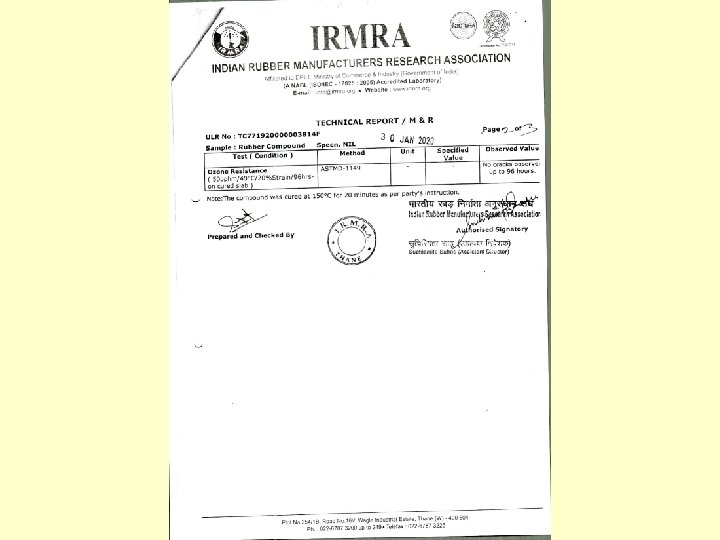
 Property Test method I. S. Specification reference Value specified")
PROPERTIES OF ELASTOMER (915. 2) Property Test method I. S. Specification reference Value specified IS: 3400 (Part IV) + 5 IRHD 3. 0 Accelerated ageing (When it is heated for a duration of 70 h & at temp 100 ± 1 o C) and allowed to cool to room temp. 3. 1 Maximum change in hardness 3. 2 Maximum change in tensile strength 3. 3 Maximum change in elongation at break 4. 0 Ozone Test – Sample is subjected to tensile strain of 20%, at 40 o C temp. & ozone concentration kept 50 pphm (parts per hundred million) , for 96 hours Not more than 15 % Not more than 30 % There should be no cracking or disintegration.
 • Shear modulus of elastomer bearing shall")
PROPERTIES OF BEARINGS (915. 2, 915. 3) • Shear modulus of elastomer bearing shall be not less than 0. 80 MPA and not more than 1. 20 MPA • Adhesion strength of elastomer to steel plates as per IS: 3400 Part XIV > 7 KN/M • Laminated Mild Steel To IS: 2062 shall be used – Fiber glass or similar fabric shall not be used
 • Thickness of internal layers shall only be – 8 mm,")
DIMENSIONING RULES (916) • Thickness of internal layers shall only be – 8 mm, 10 mm, 12 mm or 16 mm (for special use) • Thickness of outer layer – ½ Of inner layer, max 6 mm – Side cover 6 mm for all • l 0/b 0≤ 2 • h≤b 0/5 & h≥b 0/10
 ITEMS TOLERANCES 1. Overall plan dimensions -0, +6 mm")
SN DIMENSIONAL TOLERANCES (APPENDIX I) ITEMS TOLERANCES 1. Overall plan dimensions -0, +6 mm 2. Total bearing thickness -0, +5% 3. Parallelism Of top surface of bearing w. r. t. the bottom surface as datum Of one side surface w. r. t. the other as datum 1 in 200 1 in 100 4. Thick. of individual internal elastomer layer Thickness of individual outer layer + 20%, max of 2 mm -0, + 1 mm 5. Plan dimensions of laminates Thickness of laminate Parallelism of laminate with respect to bearing base as datum -3 mm, +0 + 10 % 1 in 100
 • Bearing with steel laminates shall be cast as single unit in")
FABRICATION (917) • Bearing with steel laminates shall be cast as single unit in a mould and vulcanized under heat and pressure – Vulcanising equipment/ press shall be such that between platens constant pressure/ temperature can be maintained • Mould shall be kept at uniform temperature and pressure for uniform vulcanisation
 – All bearings shall preferably be fabricated in one lot – Steel")
FABRICATION (917) – All bearings shall preferably be fabricated in one lot – Steel plates for laminates shall be sand blasted clean of all mill scale and contaminants – Rusted plates with pitting shall not be used – Edges of plates shall be rounded
 – Spacers shall be used in moulds to ensure cover and location")
FABRICATION (917) – Spacers shall be used in moulds to ensure cover and location of laminates • Hole in surface or in edge cover shall be filled in subsequently – Raw material to be put in metal dies for vulcanisation shall be weighed accurately • Homogeneous and compact bearing • No spongyness or deficiency of material shall be there – Before any batch, test pieces shall be made to monitor quality
 • Manufacturer shall have facilities for testing • Testing at manufacturer’s cost")
ACCEPTANCE (918) • Manufacturer shall have facilities for testing • Testing at manufacturer’s cost except under special conditions • Prior submittal of testing program • Any acceptance testing delayed beyond 180 days require special approval • Lot by lot inspection
 • A lot under acceptance shall comprise all bearings")
TESTING & ACCEPTANCE LOT SIZE(918) • A lot under acceptance shall comprise all bearings including the pair of extra bearings where ever applicable • A lot size of 24 or larger number of bearings shall be defined as LARGE LOT • A lot size of less than 24 bearings shall be defined as SMALL LOT – When the number of bearings for a project is large and phased production/ acceptance is permitted then number of bearings supplied in any phase of supply shall be considered as LARGE LOT for the purpose of testing
 • LEVEL-1 acceptance testing – For large lots only")
LEVELS OF ACCEPTANCE (918. 3) • LEVEL-1 acceptance testing – For large lots only – Two extra bearings to be manufactured, consumed in destructive testing • LEVEL-2 acceptance testing – For small lots only – No destructive testing unless otherwise specified
 LEVEL 1 1. General Inspection 2. Tests On")
TYPES OF TESTING (918. 4. 1) LEVEL 1 1. General Inspection 2. Tests On Specially Moulded Test Piece 3. Test On Complete Bearings Or Sections for Measurement of Various Quality Parameters
 • General inspection – All bearings visually inspected for")
LEVEL-1 TESTING (918. 4. 1) • General inspection – All bearings visually inspected for defects in surface finish, shape or any discernible defects – All bearings checked for dimensional tolerances – Application of an axial load equal to 15 MPA and visual examination for • Misalignment of laminates • Poor bond at interface • Variation in hi , he (elastomer thickness) • Any surface defects • Low stiffness
 • Tests on specially moulded test piece – Identical")
LEVEL-1 TESTING (918. 4. 1) • Tests on specially moulded test piece – Identical compounds and vulcanizing conditions as used for bearing • Check for Chemical Composition, Specific gravity, ash content etc. Physical Properties : – Hardness – Ultimate Tensile strength – Elongation at break – Compression set test – Accelerated ageing – Adhesion strength – Ozone test
 • For acceptance testing level 1,")
TESTS ON MOULDED PIECES (918. 4. 1. 2) • For acceptance testing level 1, the ash content and specific gravity of specially moulded test pieces and test bearings shall be compared • Variation acceptable – Specific gravity ± 0. 2 – Ash content ± 0. 5%
 • Ozone resistance may be waived")
TESTS ON MOULDED PIECES (918. 4. 1. 2) • Ozone resistance may be waived off when the satisfactory results of tests are available from process control record or development test data • Ozone test may not be insisted for bearings not located under adverse conditions of exposure • Process and acceptance tests for ozone by independent testing agency shall be acceptable
 • Tests on complete bearings – Randomly select two")
LEVEL-1 TESTING (918. 4. 1) • Tests on complete bearings – Randomly select two bearings from the lot – These bearings shall be excluded from the lot • Tests to be conducted – Shear modulus – Elastic modulus – Adhesion strength – Ultimate compressive strength • Bearings are not accepted (destroyed during test).
 • General inspection • Tests on specially moulded")
LEVEL-2 ACCEPTANCE TESTING (918. 4. 2) • General inspection • Tests on specially moulded test pieces – Same as level 1 inspections • Test on complete bearings – Tests for shear modulus only on two bearings • These bearing shall be part of the lot accepted.
 • As per special conditions or evidence of improper process/")
SPECIAL TEST (918. 5) • As per special conditions or evidence of improper process/ quality control – Level 1 inspection for small lots – External agency to do acceptance testing – Tests on pieces prepared from surface/ body of test bearings instead of specially moulded pieces.

TESTING • • • On random sample At room temperature Skilled person Not before 1 week after vulcanisation Test for finding (Modulus of elasticity) Ec shall precede test for (Shear Modulus) G if done on same bearing

ELASTIC MODULUS TEST

ELASTIC MODULUS TEST 1. Two bearings taken 2. Preload vertical load upto Ntest. Keep for 10 minutes and unload upto 2 MPA before test loading 3. Increase vertical load (axial load ‘N’) @ 0. 5 MPA TO 1 MPA per minute 4. Max test load corresponds to σm= 20 MPA 5. Load and deflection shall be measured at equal intervals (min 5).

ELASTIC MODULUS TEST • • Deflection measured at four edges and mean value taken Separate for both the bearings 6. Graph shall be plotted stress vs strain 7. Determine the slope which is ‘Ea’ 8. Bearing shall not show signs of defect or damage

SHEAR MODULUS
 RIGID CONCRETE SLAB (DEFLECTED) UNDER ‘H’")
SHEAR MODULUS N=5 MPA RIGID CONCRETE SLAB (FIXED) RIGID CONCRETE SLAB (DEFLECTED) UNDER ‘H’ 2 H RIGID CONCRETE SLAB (FIXED)
 1. Two test bearings 2. Preload bearings with max horizontal")
SHEAR MODULUS (APPENDIX 2) 1. Two test bearings 2. Preload bearings with max horizontal load, Htest (Ntest held constant) and release before test loading 3. Vertical Load Of 5 MPA shall be held constant 4. H increased gradually @ 0. 05 To 0. 1 MPA per min The horizontal loading H shall be increased to Htest max which corresponds to horizontal deflection equal to h (total elastomer thickness) 5. Load and deflection shall be measured at equal intervals (min 5) 6. Graph shall be plotted 7. Determine the slope which is ‘G’ 8. Value of G to be within ± 20% of 1 MPa and there should be no sign of instability , defect or damage

STRIPPING STRENGTH BEARINGS HELD IN RECESS TO PREVENT SLIPPAGE
 –")
STRIPPING STRENGTH • Cut two identical test pieces from test bearing (already tested) – – • • • >100 mm x 200 mm in plan Two opposing ends of the test piece shall be leveled at an angle of 450. Ntest corresponding to σm= 4 MPA to be held constant during test Horizontal load shall be increased gradually up to max yielding τm =3 MPA Check the test pieces for evidence of cracking or peeling or sepration at /near the interface between rubber and reinforcement layers, then deemed to have satisfactory adhesion

ULTIMATE COMPRESSIVE STRENGTH

ULTIMATE COMPRESSIVE STRENGTH • Same arrangement as for shear test may be there OR • Small section not less than 100 mm x 200 mm may be cut from test bearing • Tested to failure between plates of testing machine • Rate of loading < 10 MPA per minute • If the σm, at failure > 69 MPA, then bearing is OK
 • Bearings shall be accompanied by engineers certificate regarding acceptance.")
CERTIFICATION AND MARKING (919) • Bearings shall be accompanied by engineers certificate regarding acceptance. • Information card shall accompany – – – – – Name of manufacturer Date of manufacture Bearing dimensions Elastomer grade used Production batch no Acceptance lot no Date of testing Specific bridge location Explanation of markings.
 • Bearings shall be transported and stored carefully, avoiding damage, contamination with")
INSTALLATION (920) • Bearings shall be transported and stored carefully, avoiding damage, contamination with oil, dust, grease, exposure to sunlight and weather • Multiple bearings one after the other is not permitted • All bearings in one line of support shall be of identical dimensions.
 • The contact surface between the Bearings and Bed block must be")
INSTALLATION (920) • The contact surface between the Bearings and Bed block must be horizontal to avoid tangential force due to gravity coming on bearing -Tolerance 0. 2% perpendicular to load • Bearing to be placed Proper plan position = Tolerance ± 3 mm • Concrete surface shall be free from local irregularities = Tolerance ± 1 mm
 • For cast in situ concrete – Forms shall be easily removed")
INSTALLATION (920) • For cast in situ concrete – Forms shall be easily removed – There shall be no leakage of mortar – Mortar coming on bearing shall be removed before setting • For precast elements – Epoxy resin adhesive shall be applied • Bearings shall be placed in recesses

ANTI SLIP DEVICES • Required especially for steel girders where load is less – Bearings can slip out under vibrations
 • Exposed surface shall be maintained clean and free of grease, dirt")
MAINTENANCE (921) • Exposed surface shall be maintained clean and free of grease, dirt etc • Annual inspection to see surface is free from cracking, signs of damage, distress or deterioration • Arrangement for lifting of bridge deck shall be there hence better to use bed blocks/pedestals • Rly bridges with ballasted decks should be provided with suitable expansion joints to prevent ballast fouling the breathing space

Limitations of Elastomeric Bearings • Ordinary elastomeric bearing can’t be used as a fixed bearing • Translation allowed by elastomeric bearing is restricted by its thickness – 0. 5 to 0. 6 of thickness • Thick elastomeric pads are rather unstable • Limit of vertical load which can be placed safely on elastomeric pads – It causes excessive compression & bulging.

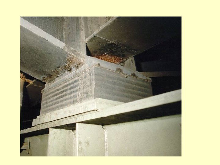
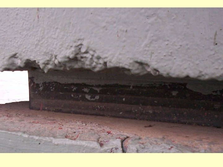
Maintenance Aspects • • • Bulging of neoprene Tearing of neoprene Tilting of bearing Disintegration of bearing (collapse, break down) Soft bearings (excess vibrations)
;")
Concrete Spalled near bearing A tilted bearing (The tilt from vertical shall be quantified); edge &60 scale

Bulging Tearing of bearings Bulging being measured with wooden straight

General Guidelines for Inspection • Shear deformation more than 50% of height of Elastomeric Pads • Rotation leading to off loading of an edge • Compression more than 5% of height of the pads

- Slides: 64