Spatial Analyzer Advanced Uncertainty Analysis The Unified Spatial


 Uncertainty Characterization • Measure the performance of the entire system")


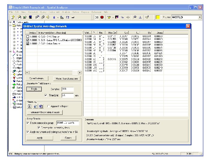

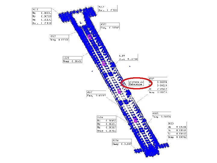
 • Disney Concert Hall Panel Positioning")
 • Long narrow structure • 350’ x 6’ trough")

 285 measured points 300 field points 11 minute run time")
")


- Slides: 56
Spatial. Analyzer Advanced Uncertainty Analysis: The Unified Spatial Metrology Network
Presentation Outline • • • Background and Motivation Instrument Uncertainty Characterization Discrete Point Cloud Uncertainty Fields Combining CASs – Traditional Approach Unified Spatial Metrology Network (USMN) Case Studies
Measurement Tools Portable CMMs Theodolites & Total Stations Digital Photogrammetry Laser Trackers Fixed CMMs Laser Scanners
Background • Many instrument types and models in use. • Each manufacturer has individual, incompatible, software applications. • Users need to apply several devices to a single measurement task. • Operators need to re-train on each software package. Combined Results Need: General Software Common User Interface Unify Metrology Processes Software A Software B Software C
Motivation • Uncertainty statements must accompany measurements. (NIST TN/1297, ISO Guide, ANSI GUM, NCSL RP-12) • Coordinate measurements used to make important (and expensive) decisions • Multiple systems are often used to perform a single measurement job. • Current industry practice is to make guesses at (or ignore) overall combined uncertainty based on instrument manufacturer specifications. • Needed: – – Instrument performance in the “real-world” Geometric representation of uncertainty Combination of measurements and uncertainty Task-Specific Uncertainty (geometrical fits, etc. )
Questions… • What is the uncertainty of my instruments in the “real-world”? • What is the effect of uncertainty propagation on the quality of my measurements? • How can I make optimal use of my measurements to minimize uncertainty? • Ok, its nice to know the uncertainty of a point, but I’m fitting a cylinder. What is the uncertainty of my fit? • What about my hidden point bar?
Unified Spatial Metrology Network Answers… • • • Combine measurement systems Characterize instrument uncertainty Verify instrument performance Determine uncertainty fields Take advantage of the relative uncertainty of the measurement components. • Geometric fitting uncertainty (sphere, line, plane, cylinder, etc)
Coordinate Acquisition System (CAS) Uncertainty Characterization • Measure the performance of the entire system under the conditions of interest. • Include instrument, operator, environment, etc. • Determine uncertainty of compensated instrument output values. • Determine effect of these uncertainties on the measured coordinates.
Instrument Example: Laser Tracker
Measurement Process • Establish a field of unknown fixed points. 56 feet
Measurement Process • Measure the points from the first instrument location.
Measurement Process • Measure the points from the second instrument location.
Measurement Process • Measure the points from the third instrument location.
Measurement Process • Measure the points from the fourth instrument location.
Solve for Instrument Transformations Point Computation: • Find • Minimize Instrument Transform Computation: Find Minimize
Extract Uncertainty from Residual Errors • Group residuals by component • “Type A” uncertainty evaluation • Result:
Coordinate Acquisition System Output with Realistic Uncertainty Statement Coordinate Acquisition System Uncertainties including all measurable effects: operator, environment, target, mechanical backlash, etc.
Instrument Performance Comparison
Uncertainty Characterization as an Operational Check Component 1 Sigma Uncertainty Before Compensation 1 Sigma Uncertainty After Compensation Typical Performance (from Table 4. 2) Horizontal Angle 3. 47 arcseconds 0. 91 arcseconds 1. 3 arcseconds Vertical Angle 11. 45 arcseconds 1. 18 arcseconds 1. 3 arcseconds Distance 0. 0087 inches 0. 000598 inches 0. 0006 inches Total measurements 32 32
Coordinate Uncertainty Fields
Uncertainty Field Density
Field Density: How many field points are needed?
Combining 2 CASs – Traditional Approach • Match common points by minimizing residuals. • Apply transformation to all points and the instrument.
Chain of CASs - Traditional Best-Fit • Transform tracker to CAD • Transform Arm to Tracker • Transform Scanner to Arm • All transformations based on XYZ coordinate residuals • Usually performed using multiple software packages
Unified Spatial Metrology Network: A Method for CAS Combination • Simultaneous combination of CASs • Relative uncertainty weighting for measurements • Determine uncertainty fields based on CAS combination. • Task-Specific: Apply uncertainty fields to downstream analysis.
Relative Uncertainty Weighting in Point Computation • Different instrument types • Different uncertainty characteristics • Weight measurement components based on relative uncertainty.
Weighting Example U m D W e
Weighting Example: 4 Measurements
USMN Uncertainty Analysis 2 Instruments Before Combination
USMN Uncertainty Field Analysis Network Solution with Actual Measured Values Composite Coordinate Set Inject U into all measurements Network Solution with Measured + U Values + Uncertainty Field
USMN Uncertainty Propagation Fixed Reference 2 Instruments After Combination
USMN Uncertainty Propagation Add a 3 rd Instrument to the Measurement Chain
USMN Uncertainty Propagation Fixed Reference Add a 3 rd Instrument to the Measurement Chain
USMN Uncertainty Propagation Fixed Reference Close the Measurement Loop to Reduce Uncertainty
Task-Specific Measurement Uncertainty • Given point uncertainties, how is my actual measurement job result affected? • What is the uncertainty of a sphere fit? • Hidden Point Bar? • Go/No Go Decision? How certain are you it’s a GO?
USMN Task-Specific Uncertainty • Given coordinate uncertainty fields…. • What is the uncertainty of the sphere fit in part coordinates?
USMN Task-Specific Uncertainty • What is the uncertainty of the measured cylinder axis and diameter?
Analysis: Hidden Point Bar Uncertainty • Uncertainty Fields Interact • End-Point is extrapolated… • And so is the uncertainty! • Yikes!
USMN Software Integration
USMN Advanced Settings
Case Studies • Aircraft Carrier Catapult Alignment (CVN-76) • Disney Concert Hall Panel Positioning • Submarine Fabrication (SSN 774) • Nuclear Power: Steam Generator Replacement
Aircraft Carrier Catapult Alignment (CVN-76) • Long narrow structure • 350’ x 6’ trough • 4 laser trackers chained together
Catapult 1, 797 Measured Points 300 field samples 15 minute run time P-4 1. 8 gigahertz
Disney Concert Hall (LA) 285 measured points 300 field points 11 minute run time P-4 1. 8 gigahertz
Submarine Fabrication (SSN-774)
296 points 1. 6 sec. for single solution 300 field points 28 minutes run time P-4 1. 3 gigahertz
Steam Generator Replacement
Uncertainty Chain 106 points 300 field points 9 minute run time P-4 1. 8 gigahertz
Uncertainty Reduced by Closing the Measurement Chain
Future Applications • Wrap optimization around USMN to determine instrument type and placement. • Expand instrument models to include the multitude of internal parameters. • Extend Task-Specific analysis to point to surface fitting and other analyses. • Extend Uncertainty to entire GD&T & FD&T analysis process – decision uncertainty.
Conclusions • It is now possible to obtain realistic geometrical uncertainty statements for combined measurement systems. • It is also possible to obtain these results on the shop floor at the technician level. • Realistic uncertainty statements provide ISO / ANSI compliant measurements. Replaces uncertainty guesses. • This information will help to educate measurement technicians and designers so they may reduce measurement uncertainty in the future.
Questions?
Mersenne Twister Random Number Generator
Attempts at Mapping Numerical Uncertainty Point in Instrument frame: X = 2. 5, Y = 4 Ux = ± 1, Uy = ± 2 Point in Part frame: X = -3, Y = 6 Ux = ? , Uy = ? Uy = ± 2 Ux = ± 1 Instrument reference frame Part reference frame