
Space X Hyperloop Competition 2019 Design of a
- Slides: 1
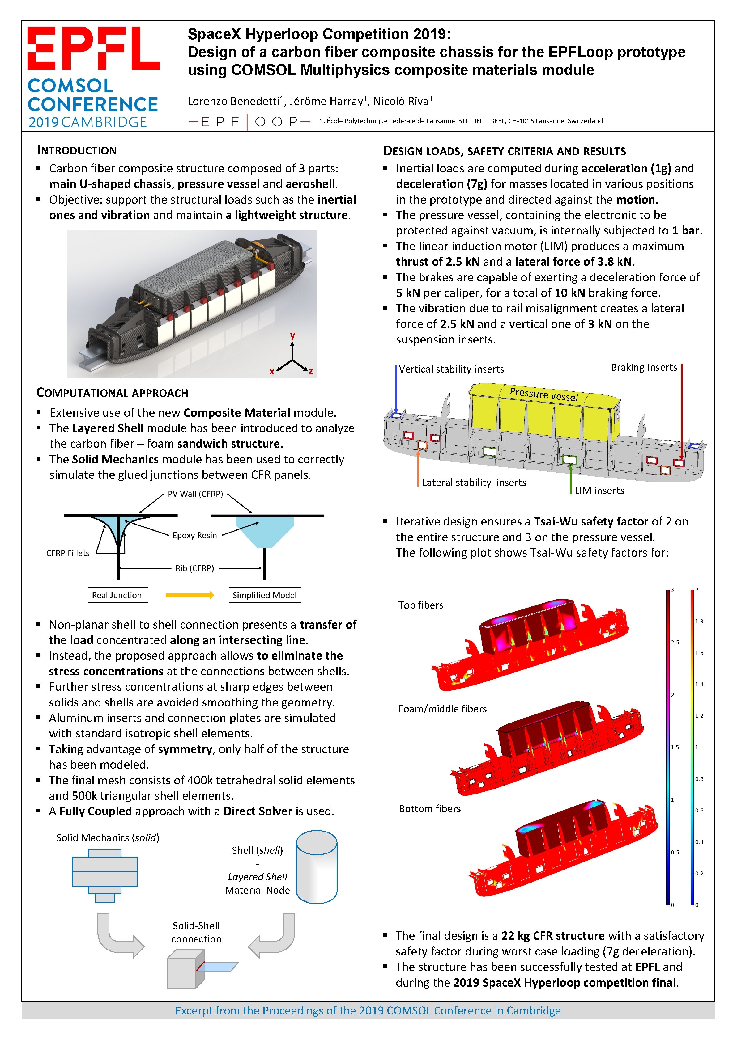
Space. X Hyperloop Competition 2019: Design of a carbon fiber composite chassis for the EPFLoop prototype using COMSOL Multiphysics composite materials module Lorenzo Benedetti 1, Jérôme Harray 1, Nicolò Riva 1 1. École Polytechnique Fédérale de Lausanne, STI – IEL – DESL, CH-1015 Lausanne, Switzerland INTRODUCTION DESIGN LOADS, SAFETY CRITERIA AND RESULTS § Carbon fiber composite structure composed of 3 parts: main U-shaped chassis, pressure vessel and aeroshell. § Objective: support the structural loads such as the inertial ones and vibration and maintain a lightweight structure. § Inertial loads are computed during acceleration (1 g) and deceleration (7 g) for masses located in various positions in the prototype and directed against the motion. § The pressure vessel, containing the electronic to be protected against vacuum, is internally subjected to 1 bar. § The linear induction motor (LIM) produces a maximum thrust of 2. 5 k. N and a lateral force of 3. 8 k. N. § The brakes are capable of exerting a deceleration force of 5 k. N per caliper, for a total of 10 k. N braking force. § The vibration due to rail misalignment creates a lateral force of 2. 5 k. N and a vertical one of 3 k. N on the suspension inserts. y x z COMPUTATIONAL APPROACH § Extensive use of the new Composite Material module. § The Layered Shell module has been introduced to analyze the carbon fiber – foam sandwich structure. § The Solid Mechanics module has been used to correctly simulate the glued junctions between CFR panels. Braking inserts Vertical stability inserts Pressure ves sel Lateral stability inserts LIM inserts § Iterative design ensures a Tsai-Wu safety factor of 2 on the entire structure and 3 on the pressure vessel. The following plot shows Tsai-Wu safety factors for: Top fibers § Non-planar shell to shell connection presents a transfer of the load concentrated along an intersecting line. § Instead, the proposed approach allows to eliminate the stress concentrations at the connections between shells. § Further stress concentrations at sharp edges between solids and shells are avoided smoothing the geometry. § Aluminum inserts and connection plates are simulated with standard isotropic shell elements. § Taking advantage of symmetry, only half of the structure has been modeled. § The final mesh consists of 400 k tetrahedral solid elements and 500 k triangular shell elements. § A Fully Coupled approach with a Direct Solver is used. Solid Mechanics (solid) Foam/middle fibers Bottom fibers Shell (shell) Layered Shell Material Node Solid-Shell connection § The final design is a 22 kg CFR structure with a satisfactory safety factor during worst case loading (7 g deceleration). § The structure has been successfully tested at EPFL and during the 2019 Space. X Hyperloop competition final. Excerpt from the Proceedings of the 2019 COMSOL Conference in Cambridge

