
Space Cowboys Progress Design Review University of Wyoming

Space Cowboys Progress Design Review University of Wyoming Kyle Fox, Sean King, Erich Lichtfuss, Jeff Parkins, Anne-Marie Suriano
Overview • • • Mission Overview Subsystem Requirements Special Requirements Block Diagrams Schematics Activity Diagram • • • Parts List Test Plans Canister Guidance Canister Shared Logistics Plan Management Issues and Concerns
Mission Overview • Objective – Accurately measure flight parameters including ambient and skin temperatures, pressure, acceleration, spin rate, and magnetic field. – Gain basic understanding of design requirements and associated hurdles for designing in real-world space applications.
Mission Overview • Goal – Provide an accurate base of flight parameters to model rocket flight conditions and patterns for assessment of associated affects on other systems. – Attain real-world design experience.
Mission Overview • Underlying Science/Theory – Recognition of magnetic field changes associated with altitude – Quantification of varying flight parameters – Attempt to determine rocket orientation using post-flight accelerometer data
Mission Overview • Previous Related Experimentation – Previous flights have included multi-sensor packages – Results provide a basis for improvement on future data collection
Mission Overview • Mission Requirements – Multipoint Temperature Monitoring – Pressure Monitoring – 3 -Axis Accelerometer Monitoring – Humidity Monitoring – 3 -Axis Gauss Meter
Mission Overview • Success Criteria – No mechanical failure of structure – No electrical failures in system – Clear and accurate data stored • Allows for analysis • Easily organized and identifiable
Mission Overview • Benefits – Other experiments on the rocket • Accurate flight data – Future rocket flights and teams • Accurate flight data • Clear identification of extreme parameters for more efficient design • Multi-sensor platform that allows for expansion to add future sensors and experiments as desired
Subsystem Requirements • Subsystems – Power – Sensors – Command & Data Handling – PCB – Support Structure
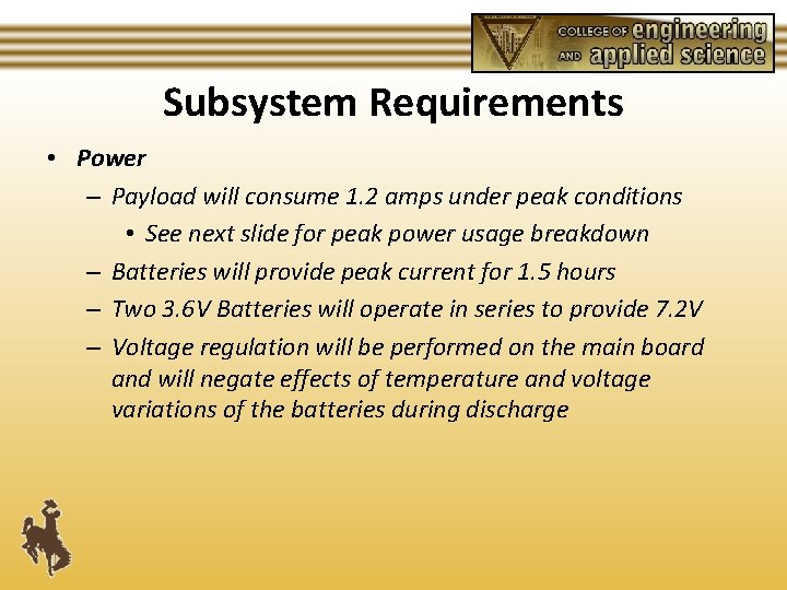
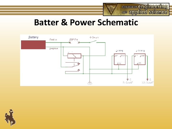
Subsystem Requirements • Power – Payload will consume 1. 2 amps under peak conditions • See next slide for peak power usage breakdown – Batteries will provide peak current for 1. 5 hours – Two 3. 6 V Batteries will operate in series to provide 7. 2 V – Voltage regulation will be performed on the main board and will negate effects of temperature and voltage variations of the batteries during discharge
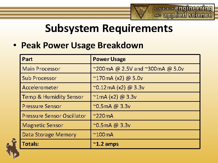
Subsystem Requirements • Peak Power Usage Breakdown Part Power Usage Main Processor ~200 m. A @ 2. 5 V and ~300 m. A @ 5. 0 v Sub Processor ~170 m. A (x 2) @ 5. 0 v Accelerometer ~0. 12 m. A (x 2) @ 3. 3 v Temp & Humidity Sensor ~1 m. A (x 2) @ 3. 3 v Pressure Sensor ~0. 5 m. A @ 3. 3 v Pressure Sensor Oscillator ~220 m. A Magnetic Sensor ~0. 5 m. A @ 3. 3 v Data Storage Memory ~100 m. A Totals: ~1. 2 amps
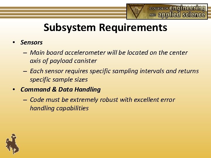
Subsystem Requirements • Sensors – Main board accelerometer will be located on the center axis of payload canister – Each sensor requires specific sampling intervals and returns specific sample sizes • Command & Data Handling – Code must be extremely robust with excellent error handling capabilities
Subsystem Requirements • PCB – Multilayer construction focusing on noise mitigation and ease of future expansion • Support Structure – Maximize strength, minimize mass
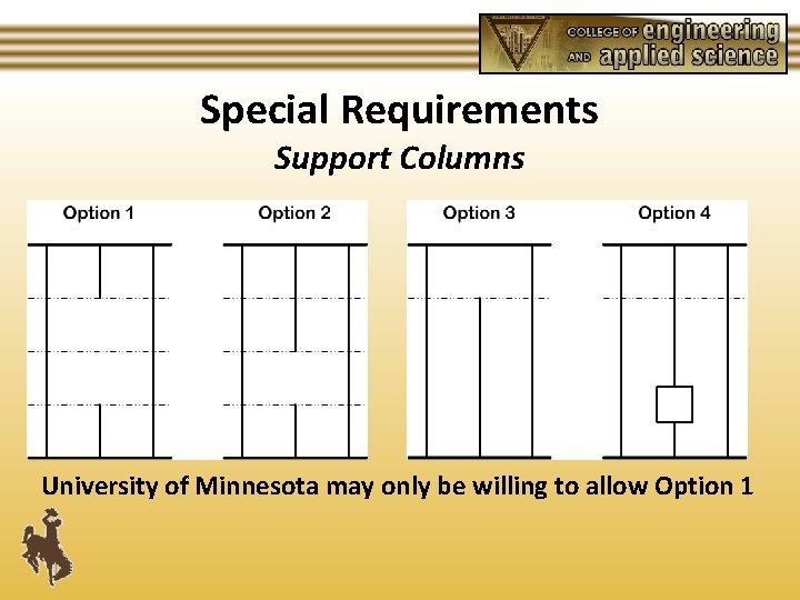
Special Requirements Support Columns University of Minnesota may only be willing to allow Option 1
Block Diagrams Main Sensor Board
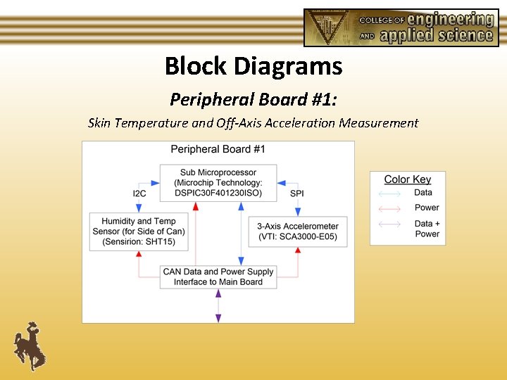
Block Diagrams Peripheral Board #1: Skin Temperature and Off-Axis Acceleration Measurement
Block Diagrams Peripheral Board #2: Magnetic Field Measurement
Batter & Power Schematic
Main Board Schematic
Peripheral Board 1 Schematic
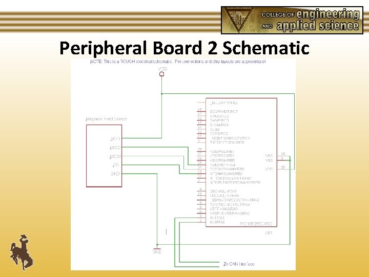
Peripheral Board 2 Schematic
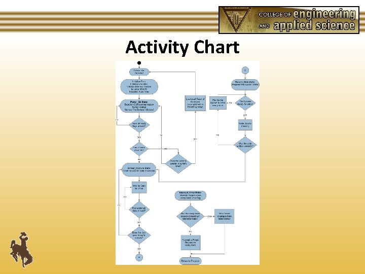
Activity Chart
Operating System • The Payload will operate with a Real Time Interrupt Driven Operating System • The Operating System will have extensive error handling capabilities including multiple sensor failures • The Operating System will be constructed to allow easy modification and expansion as required by future missions
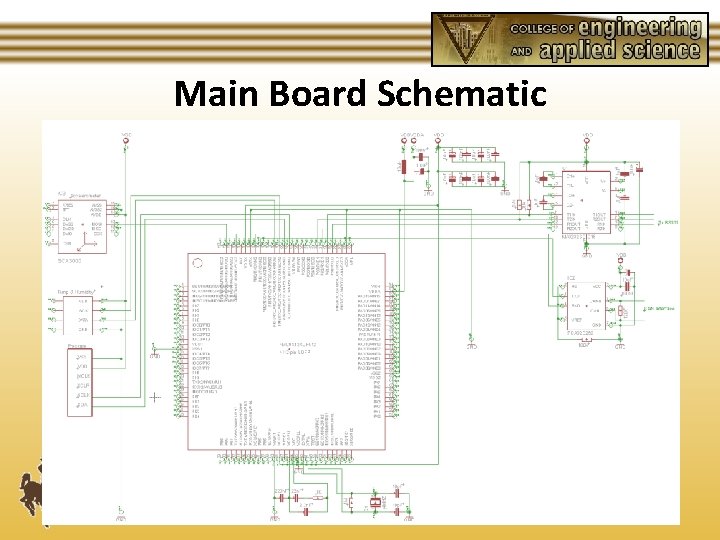
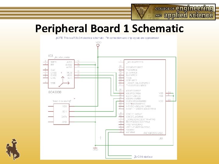
CAN bus interface • The Main Board will communicate with all satellite boards via a CAN bus Interface • CAN has the ability to address over 110 devices • CAN provides 1 MB/s throughput • CAN is commonly available and very inexpensive
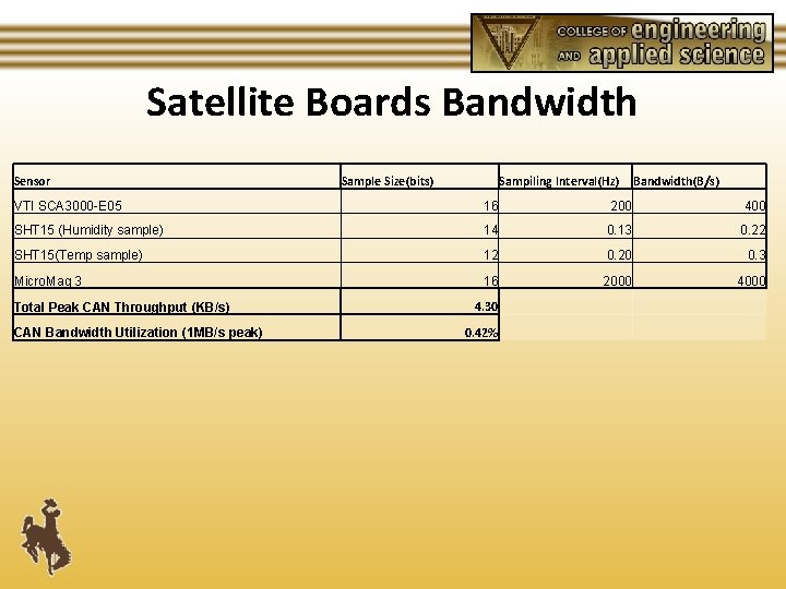
Satellite Boards Bandwidth Sensor Sample Size(bits) Sampiling Interval(Hz) Bandwidth(B/s) VTI SCA 3000 -E 05 16 200 400 SHT 15 (Humidity sample) 14 0. 13 0. 22 SHT 15(Temp sample) 12 0. 20 0. 3 Micro. Mag 3 16 2000 4000 Total Peak CAN Throughput (KB/s) CAN Bandwidth Utilization (1 MB/s peak) 4. 30 0. 42%
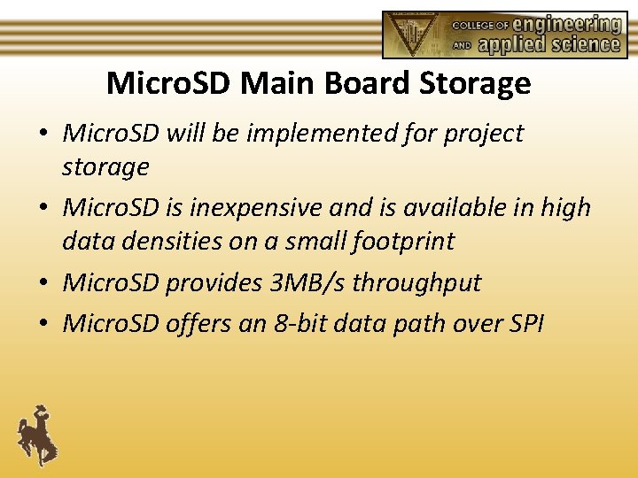
Micro. SD Main Board Storage • Micro. SD will be implemented for project storage • Micro. SD is inexpensive and is available in high data densities on a small footprint • Micro. SD provides 3 MB/s throughput • Micro. SD offers an 8 -bit data path over SPI
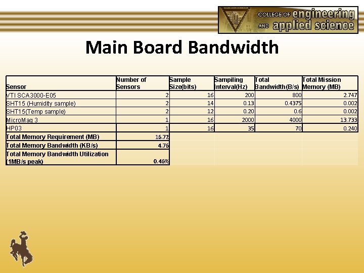
Main Board Bandwidth Sensor VTI SCA 3000 -E 05 SHT 15 (Humidity sample) SHT 15(Temp sample) Micro. Mag 3 HP 03 Total Memory Requirement (MB) Total Memory Bandwidth (KB/s) Total Memory Bandwidth Utilization (1 MB/s peak) Number of Sensors Sample Size(bits) 2 2 2 1 1 16. 72 4. 76 0. 46% Sampiling Total Mission Interval(Hz) Bandwidth(B/s) Memory (MB) 16 200 800 2. 747 14 0. 13 0. 4375 0. 002 12 0. 20 0. 6 0. 002 16 2000 4000 13. 733 16 35 70 0. 240
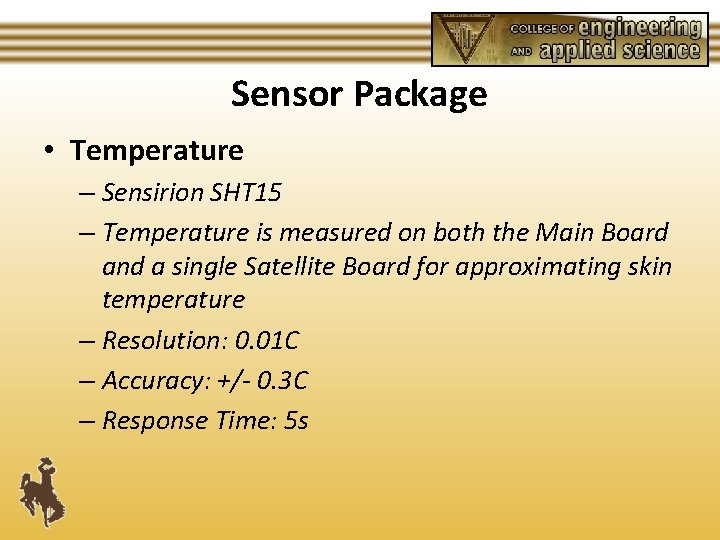
Sensor Package • Temperature – Sensirion SHT 15 – Temperature is measured on both the Main Board and a single Satellite Board for approximating skin temperature – Resolution: 0. 01 C – Accuracy: +/- 0. 3 C – Response Time: 5 s
Sensor Package • Relative Humidity – Sensirion SHT 15 – Humidity is measured on the Main Board – Resolution: 0. 05 %RH – Accuracy: +/- 3. 0 %RH – Response Time: 8 s
Sensor Package • Accelerometers – VTI SCA 3000 -E 05 – Three axis acceleration is measured along the center axis and inner edge of payload canister – Resolution: 0. 002 g – Accuracy: +/- 2. 0 % – Response Time: 200 Hz
Sensor Package • Magnetic Sensor – PNI Micro. Mag 3 – Magnetic field is measured on peripheral board #2 – Resolution: 0. 015µT – Response Time: 500µs
Sensor Package • Pressure Sensor – Hope RF HP 03 – Pressure is measured on the Main Board – Resolution: 0. 1 hpa – Accuracy: ± 0. 5 hpa – Response Time: 35 ms
Analysis • Structure – Developed mathematical models • Basis for initial design • Reviewed by ME professor – Research of Materials • Extensive properties list determined • Basic materials analysis performed
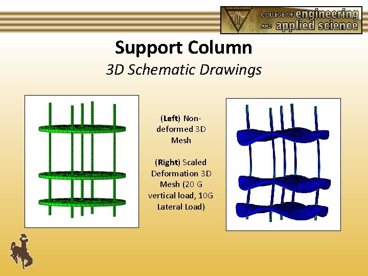
Support Column 3 D Schematic Drawings (Left) Nondeformed 3 D Mesh (Right) Scaled Deformation 3 D Mesh (20 G vertical load, 10 G Lateral Load)
Testing • Electrical – Code verification will be completed in the Code. Warrior Development Environment – Hardware verification will be completed by a series of tests TBD • Structure – Vibration testing will be completed at a local businesses 2 -axis vibration table – Spin Stabilization Testing will also be conducted at local business using a spin table
Testing • Full Package Testing – Environmental Testing using previous Rock. Sat flights data as a reference – Possible Weather Balloon Launch. Local Civil Air Patrol Squadron has offered to run our package as a payload for a future weather balloon launch.
Testing • Potential Points of Failure – Electrical • Contact to data storage card • Electrical connection breakage during high Gs • Unforeseen code interruption due to interference – Mechanical • Bolt thread shearing • Vertical supports buckling • Tray malfunction

Major Structural Components • Makrolon (Tray Material) – Bayer • Properties are known (www. Mat. Web. com) • Price & Availability known • Aluminum (Support Columns & Circuit Mounts) – Provided by University of Wyoming Engineering Machine Shop • Properties known • Prices & Availability known

Major Electrical Components • Parts List – See file “Parts List. docx” • Lead Times – 1. 5 Weeks • S+H – $50 in addition to listed part costs
Rock. Sat Payload Canister User Guide Compliance • Mass/Volume – Estimate 3 lbs • Payload Activation – G-switch activation • Open circuit until g-switch activation • Rocket Interface – RBF/Shorting wires
Shared Can Logistics Plan • University of Wyoming (UW) & University of Minnesota (UMN) • UW Missions – Multi-sensor: Rocket flight parameter measurements – Good Vibrations: Explore rocket flight effects on electrical and crystal oscillators • UMN Mission – To characterize the flight of the rocket and attempt to record data using techniques untested in suborbital flight.
Shared Can Logistics Plan • Interfacing Collaboration Plan – E-mail and phone conferencing – Exchange of 3 D modeling suggestions – Full assessment and agreement on location, structure and interface • Structural Interfacing – Still to be determined – Positioning has been discussed
Management • Project Schedule – See attachment • Preliminary mass/monetary budgets – Mass Budget: 3 lb (Multi-Sensor) – Budget: approx. $750
Conclusions • Issues/Concerns – Structural Interface with other Payloads within Canister – Electrical Interference from Payloads and External Radiation
- Slides: 45