Solid state physics Lecture 2 Xray diffraction Prof

 X-rays are electromagnetic wave with wave")


- Slides: 37
Solid state physics Lecture 2: X-ray diffraction Prof. Dr. U. Pietsch
The mean aim of Max von Laue (1912) X-rays are electromagnetic wave with wave length much smaller than wave length of visible light. X-rays are diffracted a crystal lattice 1914 Nobelpreis für Physik
Original experiment von Laue, Friedrich und Knipping Photographic film Collimator Crystal 20. April 1913 X-ray tube Ausgestellt im Deutschen Museum in München
First Laue Experiment Photographic film Erster Kristall Cu 2 SO 4 ⋅ 5 H 2 O
1912: Begin of modern Crystallography X-rays are electromagnetic waves of very short wavelength ( ~ 1 Å = 10 -10 m). Crystals are periodic structures in 3 D : interatomic distances are of similar order of magnitude as x-ray wave length X-ray diffraction is a method to determine the geometric structure of solids !
Erklärung durch Interferenz am 3 D Gitter
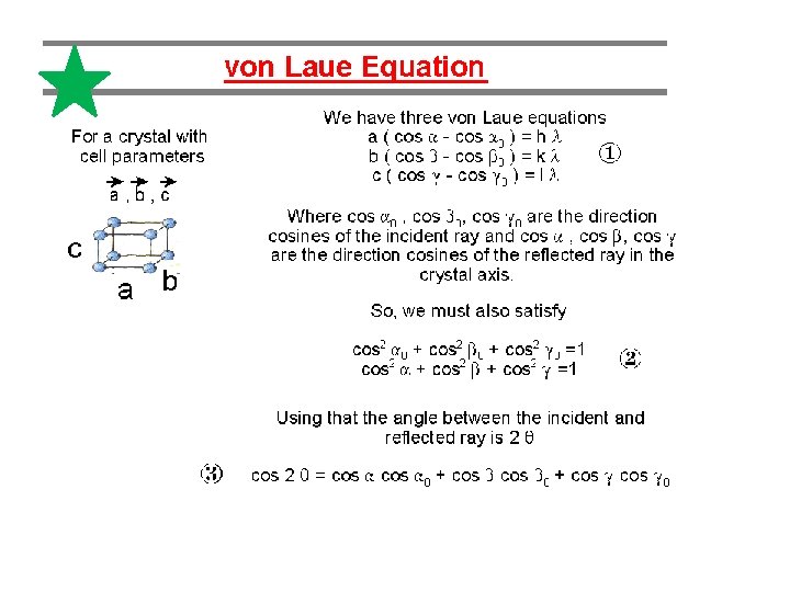
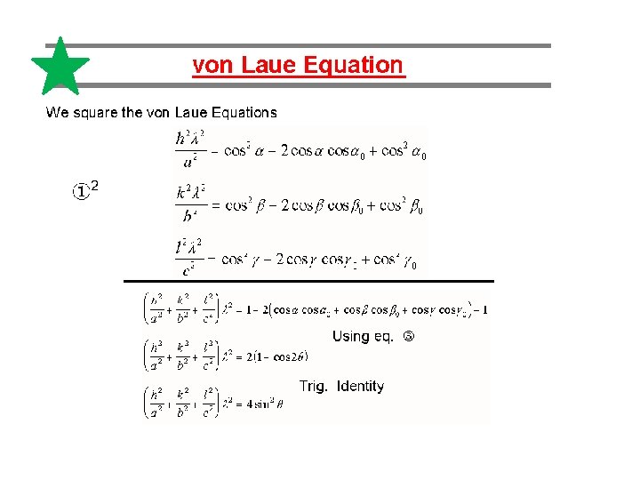
Explanation of Laue pattern
recip. lattice vector
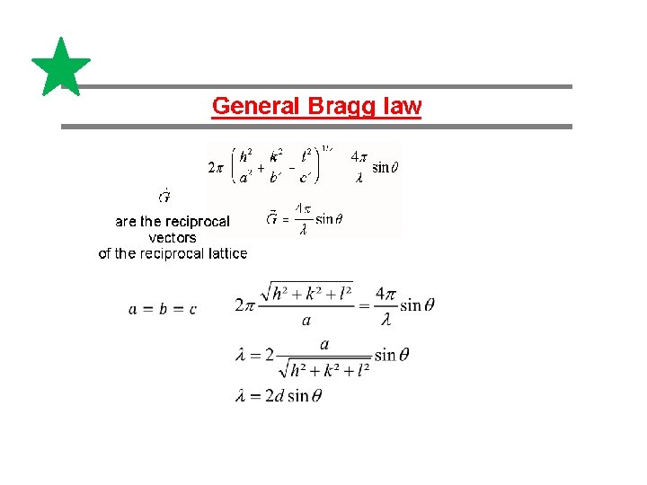
Alternative description of Laue-pattern by W. H. Bragg und W. L. Bragg Interference at dense backed „lattice planes“ Bragg equation Nl=2 dsin. Q
Reciprocal space, Ewald construction
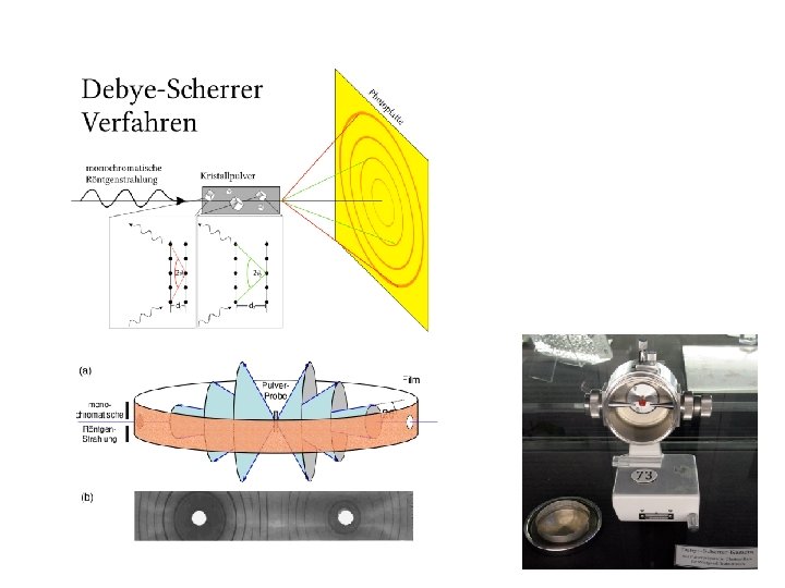
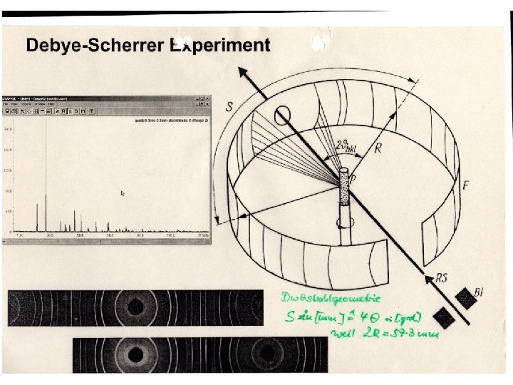
Setup of modern diffraction experiment
X-ray tube and tube spectrum E = h v = e U lmin= h c / e Ua lmin = 12. 4/Ua Characteristic radiation Bremsstrahlung
ESRF
Generation of Synchrotron radiation Electron circulates with relatvististic energy in orbit of storage ring with orbit frequency w= 106 Hz Ee = 5 Ge. V Ee is much larger compared to rest mass energy mc², g = 5 Ge. V/ 0. 511 Ge. V≈ 104 value 1/g is the vertical open angle Using g one can estimate the electron velocity
Generation of Synchrotron radiation Supposing the circulating electron emits a photon at point A of orbit. M Elektron proceeds to point C via B on orbit. At point C it emits a second photon. For the electron the length AC (electron) = v* dt. For the photon emitted in A reaches this distance is AC(photon = c *dt The spatial distance between both waves : (c-v) dt An observer at point C the light pulse has a length
Generation of Synchrotron radiation Considering the opening angle a = 1/g due to electron orbit For a =0 Dilatation of time a consequences for spectral distribution of photon emission Orbit time of electron along AC differs from time of photon
Generation of Synchrotron radiation Inverse pulse length determines the spectral with of light emission The emission spectrum has a critical wave length given by This is x-ray range. In energy :
Generation of Synchrotron radiation Bending radius R of electron orbit is Emission power is For ESRF, E=6 Ge. V, B=0. 8 T R= 24. 8 m
wc Bend magnet spectrum Well predictable ESRF
Kinematic X-ray scattering Dipole scattering of x-ray wave by an electron: Electron excites dipole radiation f Superposition of dipole radiation generated by two electrons at positions X 1 and X 2 For n electrons Stotal scattering amplitude of one atom : atomic form factor
Kinematic X-ray scattering Scattering by all electrons of one atom : atomic formfactor Form factor f[(s-s 0)/l] result from quantun mechanical calculations f(0) = Z ; f[(s-s 0)/l] decays continuosly as function of (s-s 0)/l
Kinematic X-ray scattering Scattering by two atoms : Scattering by many disordered atoms : Debye´sche Streugleichung Debye equation
Kinematic X-ray scattering Scattering by „small“ crystal: rnm= Rnm+rn distances between unit cells shape factor, distances betwen atoms within one unit cell structure factor Summation over all unit cells N 1 a 1 , N 2 a 2 , N 3 a 3 FWHM
Kinematic X-ray scattering I <> 0 only in near vicinity of the peak maxima h, k, l integer FWHM of a Bragg peak can be approximated FWHM B(2 Q) is inversely proportional to crystal size L
Structure factor F Examples
bcc- structure: xyz = 000, ½ ½ ½ F= 2 f if h+k+l = even; F= 0 if h+k+l odd fcc- structure: xyz = 000, ½ ½ 0, ½ 0 ½ , 0 ½ ½ F= 4 f if h, k, l all are even or odd; F= 0 if h, k, l are mixed hcp- structure: xyz = 000, 1/3 2/3 ½ F= 2 f if h+2 k =3 n, l even; F= √ 3 f if h+2 k= 3 n+1, l odd F= 0 if h+2 k= 3 n+1 l even
Extinktion rules Not all combinations of h, k, l are „allowed“ , Bragg peak intensity can be vanishing due to crystal (point group ) symmetry In fcc system, only reflections appear with h²+k²+l² = 2, 4, 8, 11, 12…. = 111, 200, 220, 311, 222, …. . In Na. Cl 111, 311…. . Are weak reflectons 220, 400…. . Are strong reflections In Zn. Se 220, 400……. strong 111, 311……. middle 200, 222……. weka Structure (point group) identification considering extinktion rules and Bragg peak intensities
Powder diffraction pattern from Cd. Se Nanowires
Debye-Waller Factor Due to thermal atom oscillations X-ray intensity becomes damped, Bragg peaks exit
Data evaluation
Electron charge density distribution from x -ray diffraction data Electronic charge density of silicon Valence charge density difference charge density (bonding charges) U. Pietsch phys. stat. sol. (b) 137, 441, (1986)
Electron density distribution of Ga. As from x-ray diffraction data Ga As As Ga Valence charge density difference charge density (bonding charges)