
SOLEIL UPGRADE IDEAS Amor Nadji On behalf of
SOLEIL UPGRADE IDEAS Amor Nadji On behalf of Synchrotron SOLEIL team LER workshop SOLEIL 26 – 28 October 2016 1
PLAN • Key features of the current lattice • Beamlines (distribution, photon spectrum and brilliance) • Modes of operation and performances • Current short term projects • First thoughts about a major upgrade – Strategy – Constraints and challenges – First ideas • Summary 2

SOLEIL: 3 rd Generation Synchrotron Light Source Storage Ring Main Parameters Ø Commissioning of the Storage Ring: June-December 2006 Parameters Values Energy ( Ge. V ) 2. 75 Circumference (m)/RF frequency ( MHz ) 354. 097 / 352. 202 Betatron Tunes 18. 1580 / 10. 2280 Momentum Compaction α 1 / α 2 4. 5 x 10 -4 / 4. 6 x 10 -3 Emittance H ( nm. rad ) 3. 9 Energy spread 1. 016 x 10 -3 Coupling, εV/εH 1% Current Multibunch mode ( m. A ) 500 Average Pressure ( mbar ) 5 x 10 -10 Beam Lifetime ( h ) 12 h Ø First external users: January 2008. 3
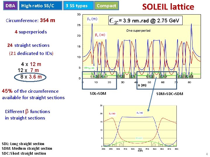
DBA High ratio SS/C 3 SS types Compact SOLEIL lattice ex 0 = 3. 9 nm. rad @ 2. 75 Ge. V Circumference: 354 m 4 superperiods One superperiod 24 straight sections (21 dedicated to IDs) 4 x 12 m 12 x 7 m 8 x 3. 6 m 45% of the circumference 45% available for straight sections SDL+SDM SDM+SDC+SDM Different b functions in straight sections SDL: Long straight section SDM: Medium straight section SDC: Short straight section 4
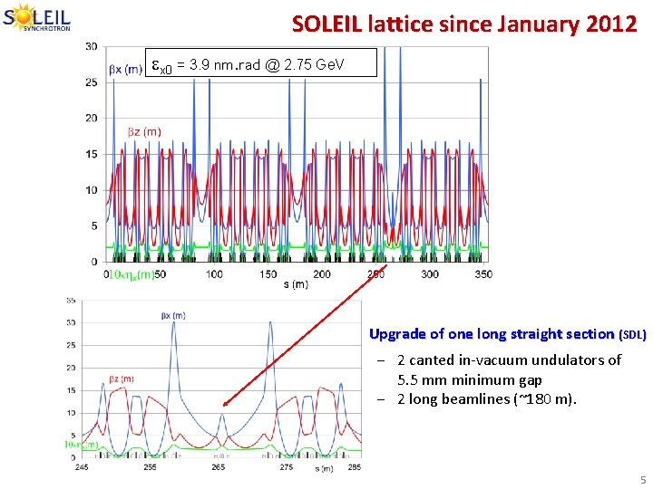
SOLEIL lattice since January 2012 ex 0 = 3. 9 nm. rad @ 2. 75 Ge. V Upgrade of one long straight section (SDL) ‒ 2 canted in-vacuum undulators of 5. 5 mm minimum gap ‒ 2 long beamlines (~180 m). 5
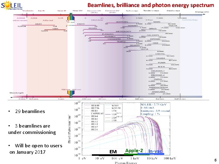
Beamlines, brilliance and photon energy spectrum • 29 beamlines • 3 beamlines are under commissioning • Will be open to users on January 2017 EM Apple-2 In-vac 66
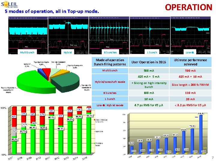
OPERATION 5 modes of operation, all in Top-up mode. Multibunch Hybrid 8 bunches 1 bunch Low- Mode of operation Bunch filling patterns User Operation in 2016 Ultimate performance achieved Multibunch 500 m. A 425 m. A + 5 m. A 425 m. A + 10 m. A Hybrid/camshaft mode + Slicing on high intensity bunch Slice length < 200 fs FWHM 8 bunches 100 m. A 110 m. A 1 bunch 16 m. A 20 m. A Low- : Hybrid mode 4. 7 ps RMS for 65 µA < 3. 2 ps RMS for 15 µA 7
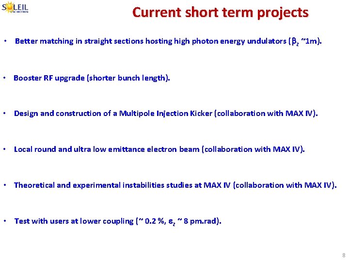
Current short term projects • Better matching in straight sections hosting high photon energy undulators (bz ~1 m). • Booster RF upgrade (shorter bunch length). • Design and construction of a Multipole Injection Kicker (collaboration with MAX IV). • Local round and ultra low emittance electron beam (collaboration with MAX IV). • Theoretical and experimental instabilities studies at MAX IV (collaboration with MAX IV). • Test with users at lower coupling (~ 0. 2 %, ez ~ 8 pm. rad). 8
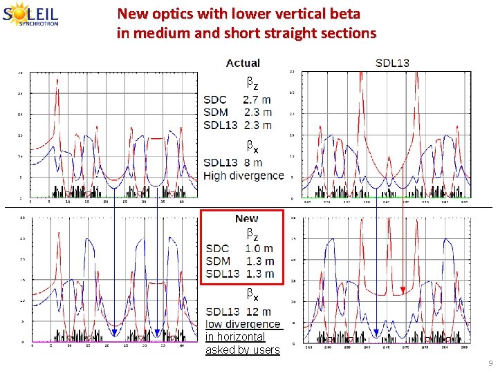
New optics with lower vertical beta in medium and short straight sections bz bx in horizontal asked by users 9
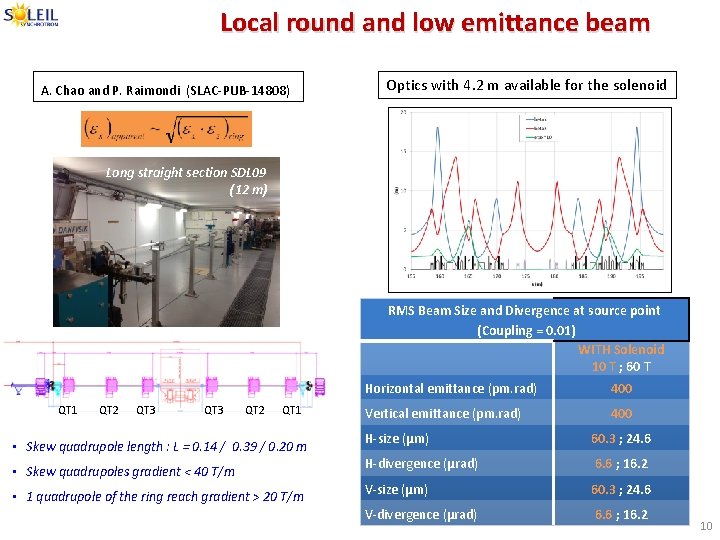
Local round and low emittance beam A. Chao and P. Raimondi (SLAC-PUB-14808) Optics with 4. 2 m available for the solenoid Long straight section SDL 09 (12 m) RMS Beam Size and Divergence at source point (Coupling = 0. 01) WITH Solenoid 10 T ; 60 T QT 1 QT 2 QT 3 QT 2 QT 1 • Skew quadrupole length : L = 0. 14 / 0. 39 / 0. 20 m • Skew quadrupoles gradient < 40 T/m • 1 quadrupole of the ring reach gradient > 20 T/m Horizontal emittance (pm. rad) 400 Vertical emittance (pm. rad) 400 H-size (µm) 60. 3 ; 24. 6 H-divergence (µrad) 6. 6 ; 16. 2 V-size (µm) 60. 3 ; 24. 6 V-divergence (µrad) 6. 6 ; 16. 2 10
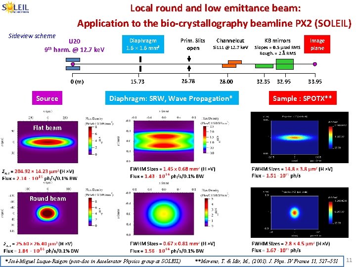
Local round and low emittance beam: Application to the bio-crystallography beamline PX 2 (SOLEIL) Sideview scheme U 20 th 9 harm. @ 12. 7 ke. V 0 (m) Source Diaphragm 1. 6 × 1. 6 mm² 15. 73 Prim. Slits open 26. 78 Channelcut KB mirrors Si 111 @ 12. 7 ke. V Slopes = 0. 5 µrad RMS Rough. = 2 Å RMS 28. 00 32. 35 Diaphragm: SRW, Wave Propagation* 32. 95 Image plane 33. 95 Sample : SPOTX** Flat beam Round beam * José-Miguel Luque-Raigon (post-doc in Accelerator Physics group at SOLEIL) ** Moreno, T. & Idir, M. , (2001). J. Phys. IV France 11, 527– 531 11
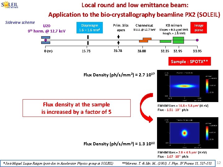
Local round and low emittance beam: Application to the bio-crystallography beamline PX 2 (SOLEIL) Sideview scheme U 20 th 9 harm. @ 12. 7 ke. V 0 (m) Diaphragm 1. 6 × 1. 6 mm² 15. 73 Prim. Slits open 26. 78 Channelcut KB mirrors Si 111 @ 12. 7 ke. V Slopes = 0. 5 µrad RMS Rough. = 2 Å RMS 28. 00 32. 35 32. 95 Image plane 33. 95 Sample : SPOTX** Flux Density (ph/s/mm 2) = 2. 7 1017 Flux density at the sample is increased by a factor of 5 Flux Density (ph/s/mm 2) = 1. 3 1018 * José-Miguel Luque-Raigon (post-doc in Accelerator Physics group at SOLEIL) ** Moreno, T. & Idir, M. , (2001). J. Phys. IV France 11, 527– 531 12
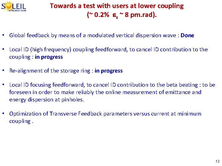
Towards a test with users at lower coupling (~ 0. 2% ez ~ 8 pm. rad). • Global feedback by means of a modulated vertical dispersion wave : Done • Local ID (high frequency) coupling feedforward, to cancel ID contribution to the coupling : in progress • Re-alignment of the storage ring : in progress • Local ID focusing feedforward, to cancel ID contribution to the beta beating : to be foreseen in order to make reliably the online measurement of emittance and energy dispersion at pinholes. • Optimization of Transverse Feedback parameters versus current at minimum coupling. 13
First thoughts about a major upgrade: • Strategy • Constraints and challenges • First ideas 14
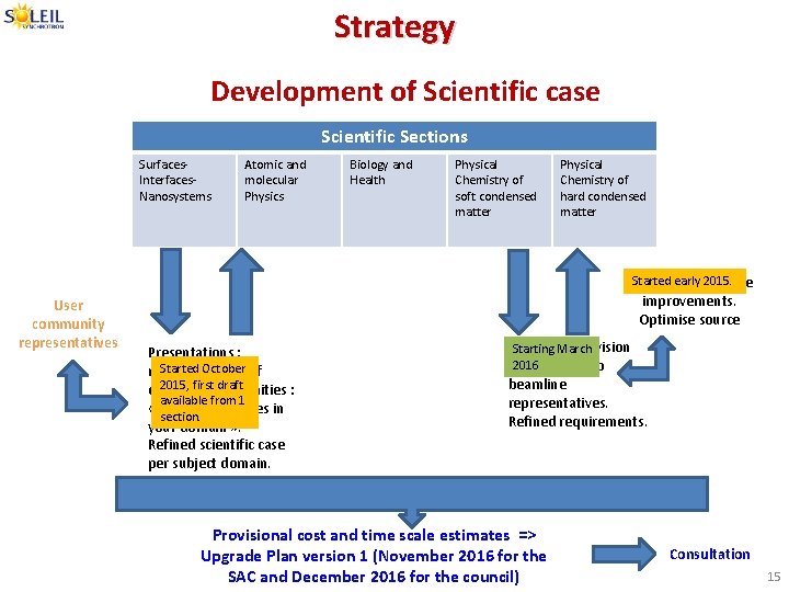
Strategy Development of Scientific case Scientific Sections Surfaces. Interfaces. Nanosystems User community representatives Atomic and molecular Physics Biology and Health Physical Chemistry of soft condensed matter Physical Chemistry of hard condensed matter Started early 2015. Proposals for source improvements. Optimise source Presentations : Started October representatives of 2015, first draft different communities : available from 1 « Future challenges in section. your domain » . Refined scientific case per subject domain. Accelerator division Starting March 2016 presentation to beamline representatives. Refined requirements. Provisional cost and time scale estimates => Upgrade Plan version 1 (November 2016 for the SAC and December 2016 for the council) Consultation 15
Strategy q The Final requirements should derive from future science goals. q Target date: 2025 q First directions: • Higher brilliance and coherence fraction. • Short « intense » pulses. 16
• Constraints and Challenges – Get more than a factor 10 lower H-emittance (< 400 pm. rad). – Keep circumference, tunnel & hall. – Keep beamlines source points. – Serves very broad photon energy range: from IR to 30 ke. V on undulators and to 80 ke. V on wigglers. – Re-use injector: Linac & booster. – Radiation shielding. • Main challenges: ‒ Small circumference (354 m). ‒ Presence of short straight sections. ‒ Versatile communities. 17

First Ideas 18
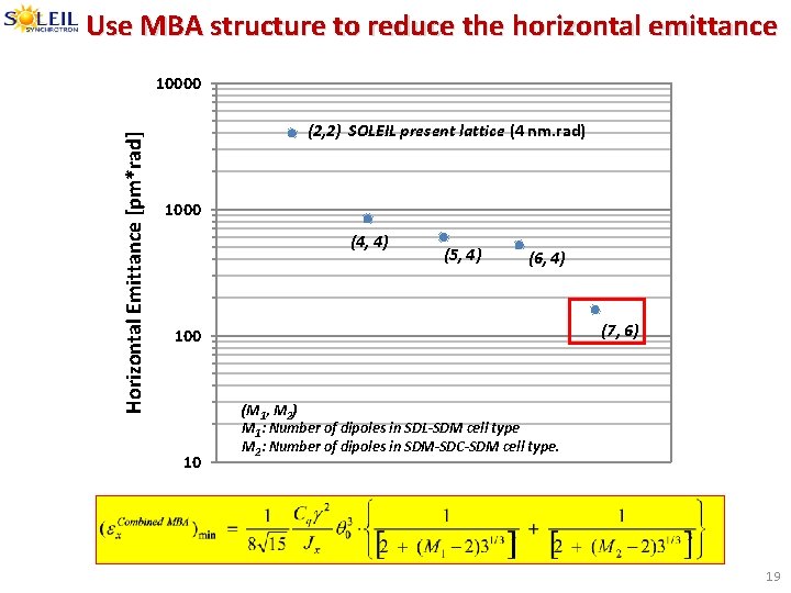
Use MBA structure to reduce the horizontal emittance Horizontal Emittance [pm*rad] 10000 (2, 2) SOLEIL present lattice (4 nm. rad) 1000 (4, 4) (5, 4) (6, 4) (7, 6) 100 10 (M 1, M 2) M 1: Number of dipoles in SDL-SDM cell type M 2: Number of dipoles in SDM-SDC-SDM cell type. 19
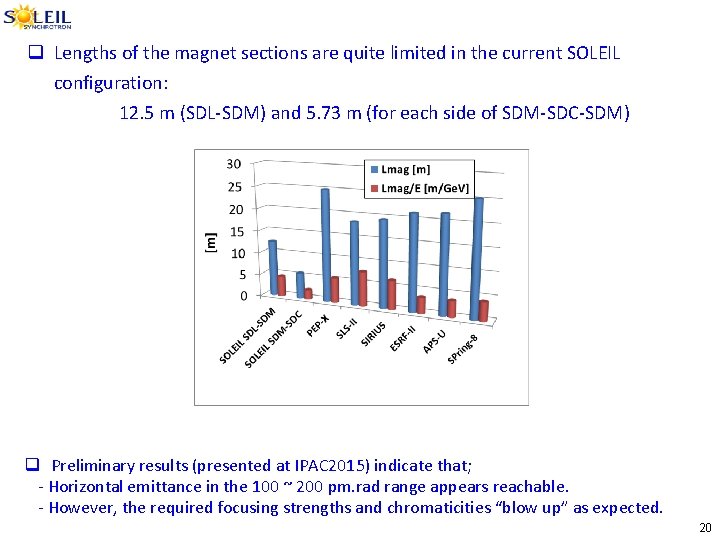
q Lengths of the magnet sections are quite limited in the current SOLEIL configuration: 12. 5 m (SDL-SDM) and 5. 73 m (for each side of SDM-SDC-SDM) q Preliminary results (presented at IPAC 2015) indicate that; - Horizontal emittance in the 100 ~ 200 pm. rad range appears reachable. - However, the required focusing strengths and chromaticities “blow up” as expected. 20
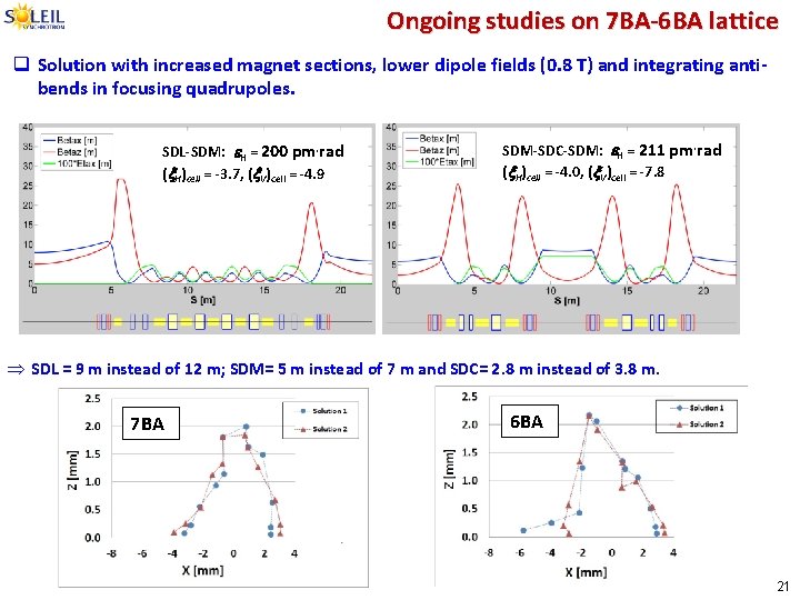
Ongoing studies on 7 BA-6 BA lattice q Solution with increased magnet sections, lower dipole fields (0. 8 T) and integrating antibends in focusing quadrupoles. SDL-SDM: e. H = 200 pm. rad (x. H)cell = -3. 7, (x. V)cell = -4. 9 SDM-SDC-SDM: e. H = 211 pm. rad (x. H)cell = -4. 0, (x. V)cell = -7. 8 Þ SDL = 9 m instead of 12 m; SDM= 5 m instead of 7 m and SDC= 2. 8 m instead of 3. 8 m. 7 BA 6 BA 21
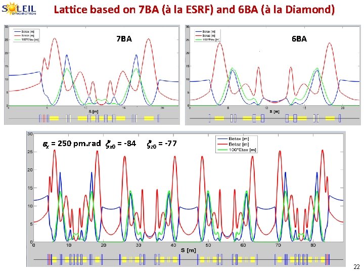
Lattice based on 7 BA (à la ESRF) and 6 BA (à la Diamond) 7 BA ex = 250 pm. rad xx 0 = -84 6 BA xz 0 = -77 22
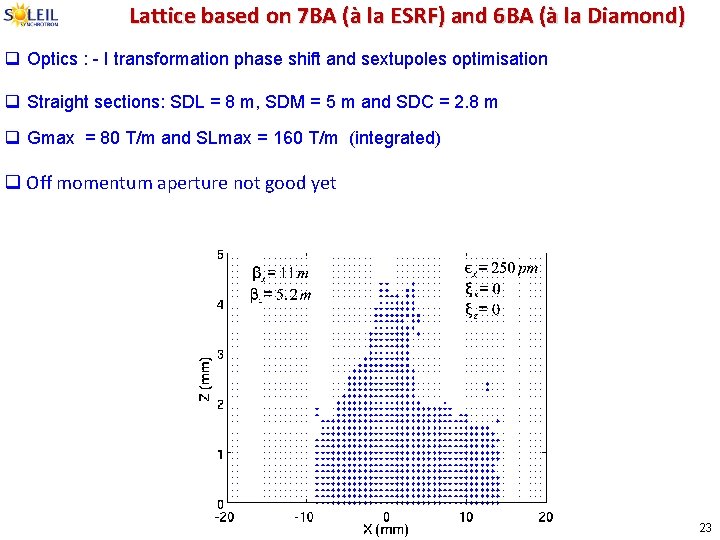
Lattice based on 7 BA (à la ESRF) and 6 BA (à la Diamond) q Optics : - I transformation phase shift and sextupoles optimisation q Straight sections: SDL = 8 m, SDM = 5 m and SDC = 2. 8 m q Gmax = 80 T/m and SLmax = 160 T/m (integrated) q Off momentum aperture not good yet 23
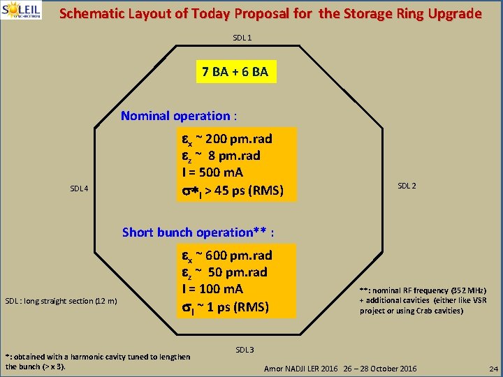
Schematic Layout of Today Proposal for the Storage Ring Upgrade SDL 1 7 BA + 6 BA Nominal operation : SDL 4 ex ~ 200 pm. rad ez ~ 8 pm. rad I = 500 m. A s*l > 45 ps (RMS) SDL 2 Short bunch operation** : SDL : long straight section (12 m) ex ~ 600 pm. rad ez ~ 50 pm. rad I = 100 m. A sl ~ 1 ps (RMS) *: obtained with a harmonic cavity tuned to lengthen the bunch (> x 3). **: nominal RF frequency (352 MHz) + additional cavities (either like VSR project or using Crab cavities) SDL 3 Amor NADJI LER 2016 26 – 28 October 2016 24
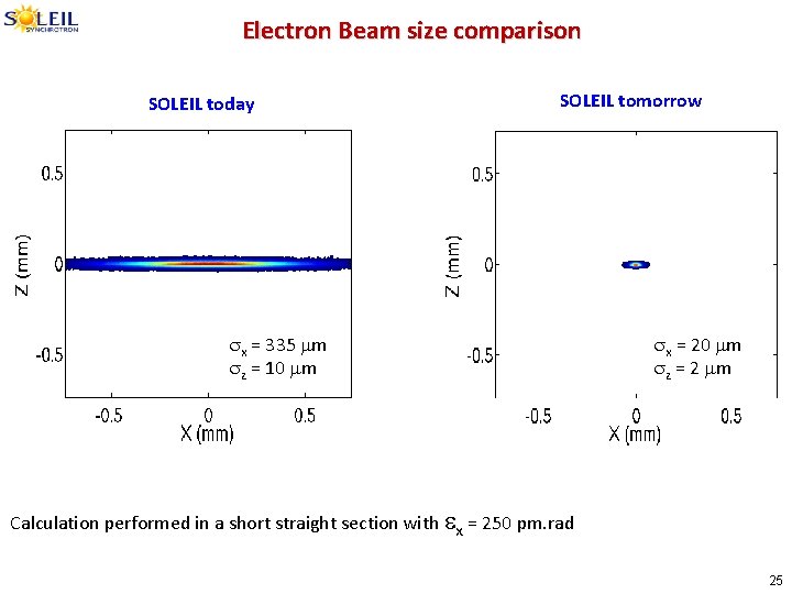
Electron Beam size comparison SOLEIL today SOLEIL tomorrow sx = 335 mm sz = 10 mm sx = 20 mm sz = 2 mm Calculation performed in a short straight section with ex = 250 pm. rad 25
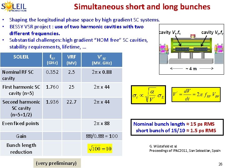
Simultaneous short and long bunches • Shaping the longitudinal phase space by high gradient SC systems. • BESSY VSR project : use of two harmonic cavities with two different frequencies. • Substantial challenges: high gradient “HOM free” SC cavities, stability requirements, lifetime, … SOLEIL f. RF V’RF (GHz) (MV. GHz) 0. 352 2. 5 2 p x 0. 88 First harmonic SC 1. 760 cavity (n=5) 25 2 p x 44 Second harmonic 1. 936 SC cavity (n=5+1/2) 22. 7 2 p x 44 Nominal RF SC cavity Even fixed points 2 p x 88 Gain 88/0. 88 = 100 Bunch length reduction (very preliminary) Nominal bunch length ≈ 15 ps RMS short bunch of 15/10 ≈ 1. 5 ps RMS G. Wüstefeld et al. Proceedings of IPAC 2011, San Sebastian, Spain 26
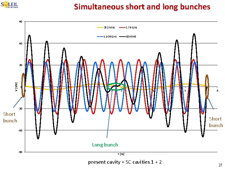
Simultaneous short and long bunches 60 352 MHz 1. 76 GHz 1. 936 GHz SOMME 40 V [MV] 20 Short bunch 0 0 1 2 3 4 5 6 -20 Short bunch -40 Long bunch -60 t [ns] present cavity + SC cavities 1 + 2 27
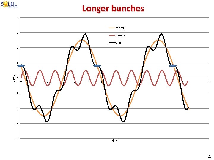
t[ns] V [MV]
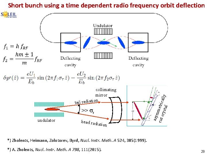
Short bunch using a time dependent radio frequency orbit deflection collimating mirror tail radiation >> sr undulator head rad iation asym cut metric crys a tal lly *) Zholents, Heimann, Zolotorev, Byrd, Nucl. Instr. Meth. A 524, 385(1999). *) A. Zholents, Nucl. Instr. Meth. A 798, 111(2015). 29
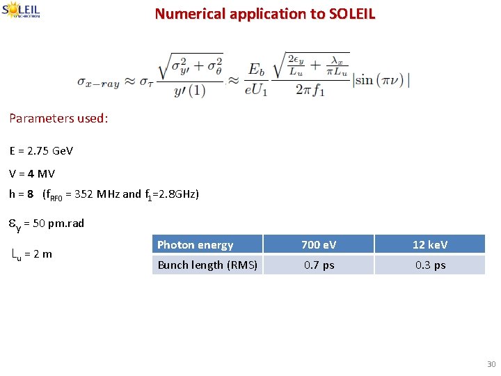
Numerical application to SOLEIL Parameters used: E = 2. 75 Ge. V V = 4 MV h = 8 (f. RF 0 = 352 MHz and f 1=2. 8 GHz) ey = 50 pm. rad Lu = 2 m Photon energy 700 e. V 12 ke. V Bunch length (RMS) 0. 7 ps 0. 3 ps 30
SUMMARY q 26 beamlines are open to the users, 3 are under commissioning, to be opened by January 2017. q 5 modes of operation (all in Top-up) + Femto. Slicing operation (since 14/03/2016). q Good availability of the beam (98. 9 % in 2015) and good MTBF (105 h in 2015). q Short term projects towards improvement of the storage ring operation. q First thoughts for a major upgrade of the facility to satisfy science goals. Ø Horizontal emittance ~200 pm. rad → MBA Ø Short “intense” pulses ~1 ps → High gradient SC RF systems or deflecting RF kicks. 31
- Slides: 31