
Solar Powered Water Sterilization System with Microplasma Ozone







- Slides: 42
Solar Powered Water Sterilization System with Microplasma Ozone Generator ECE 445: Senior Design Team #14: Matt Dubois, Albert Lo, Eric Liu Fall 2012
Agenda Goal Device Overview Bill of Materials Feature and Benefits Hardware Modules and Testing Solar Panel Solar Charge Controller Battery Flyback Converter Reactor Circuit Half-Bridge Pump Reactor Micro-Controller Other Tests Recommendations Ethics
Goal Provide 3 rd World Countries with a efficient solution to sanitize contaminated water
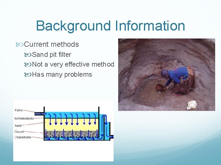
Background Information Current methods Sand pit filter Not a very effective method Has many problems
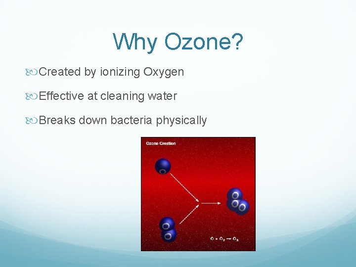
Why Ozone? Created by ionizing Oxygen Effective at cleaning water Breaks down bacteria physically
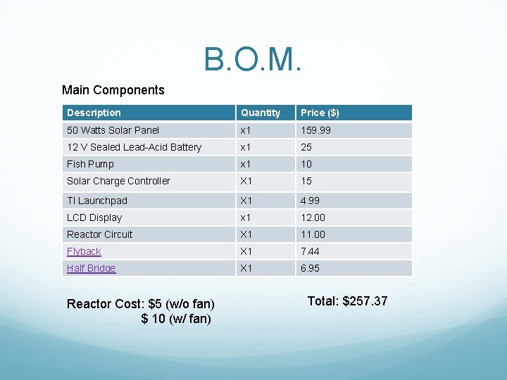
B. O. M. Main Components Description Quantity Price ($) 50 Watts Solar Panel x 1 159. 99 12 V Sealed Lead-Acid Battery x 1 25 Fish Pump x 1 10 Solar Charge Controller X 1 15 TI Launchpad X 1 4. 99 LCD Display x 1 12. 00 Reactor Circuit X 1 11. 00 Flyback X 1 7. 44 Half Bridge X 1 6. 95 Reactor Cost: $5 (w/o fan) $ 10 (w/ fan) Total: $257. 37
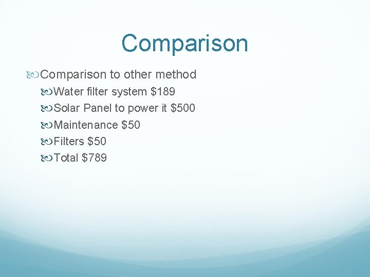
Comparison to other method Water filter system $189 Solar Panel to power it $500 Maintenance $50 Filters $50 Total $789
Device Overview Solar Powered Water Sterilization System with Microplasma Ozone Generator offers a cheap and efficient method to clean contaminated water Utilizes compact ozone reactor to clean contaminated water
Features and Benefits Cheap Efficient Self-Sustaining System Eco-Friendly
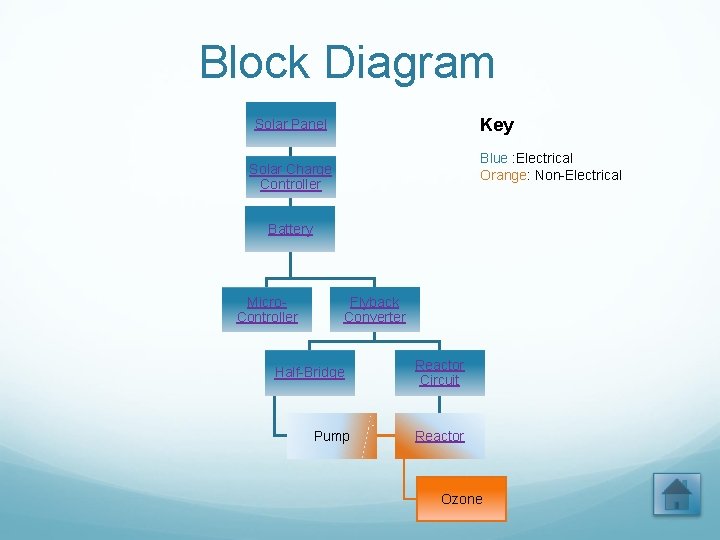
Block Diagram Key Solar Panel Blue : Electrical Orange: Non-Electrical Solar Charge Controller Battery Micro. Controller Flyback Converter Half-Bridge Pump Reactor Circuit Reactor Ozone
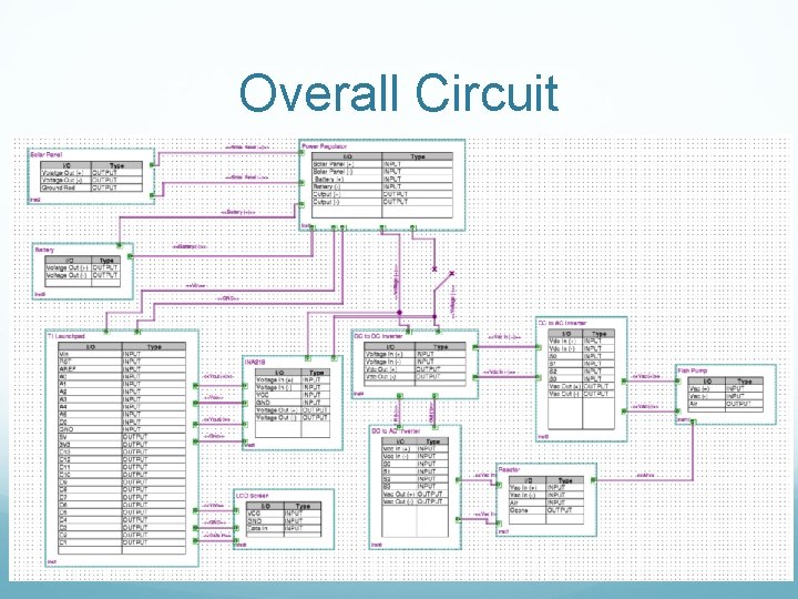
Overall Circuit
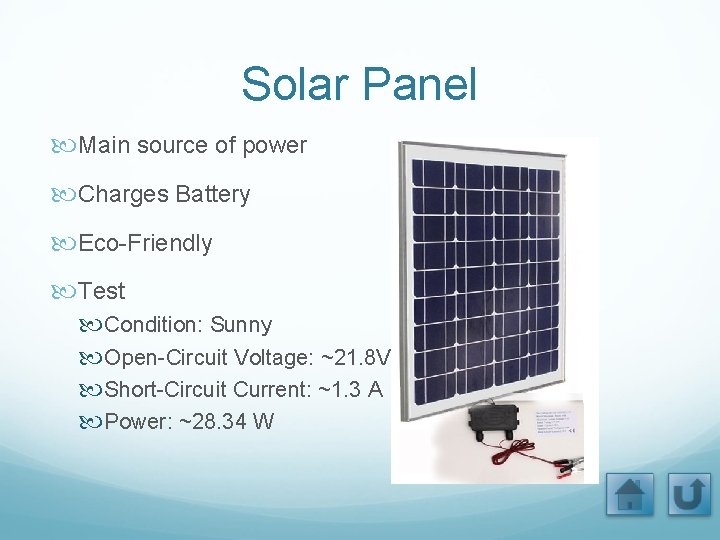
Solar Panel Main source of power Charges Battery Eco-Friendly Test Condition: Sunny Open-Circuit Voltage: ~21. 8 V Short-Circuit Current: ~1. 3 A Power: ~28. 34 W
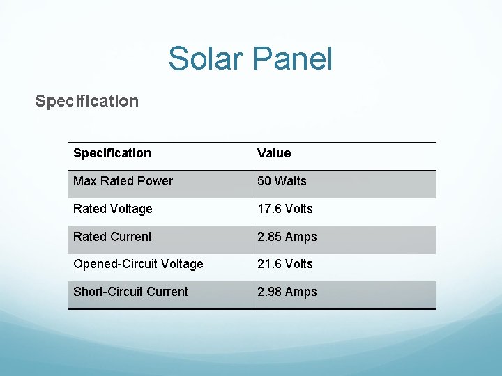
Solar Panel Specification Value Max Rated Power 50 Watts Rated Voltage 17. 6 Volts Rated Current 2. 85 Amps Opened-Circuit Voltage 21. 6 Volts Short-Circuit Current 2. 98 Amps
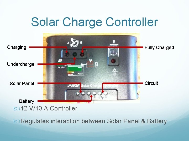
Solar Charge Controller Charging Fully Charged Undercharge Solar Panel Circuit Battery 12 V/10 A Controller Regulates interaction between Solar Panel & Battery
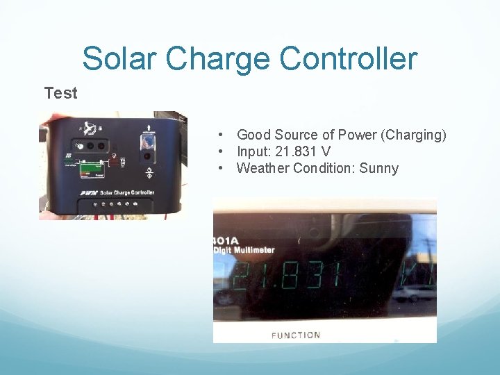
Solar Charge Controller Test • Good Source of Power (Charging) • Input: 21. 831 V • Weather Condition: Sunny
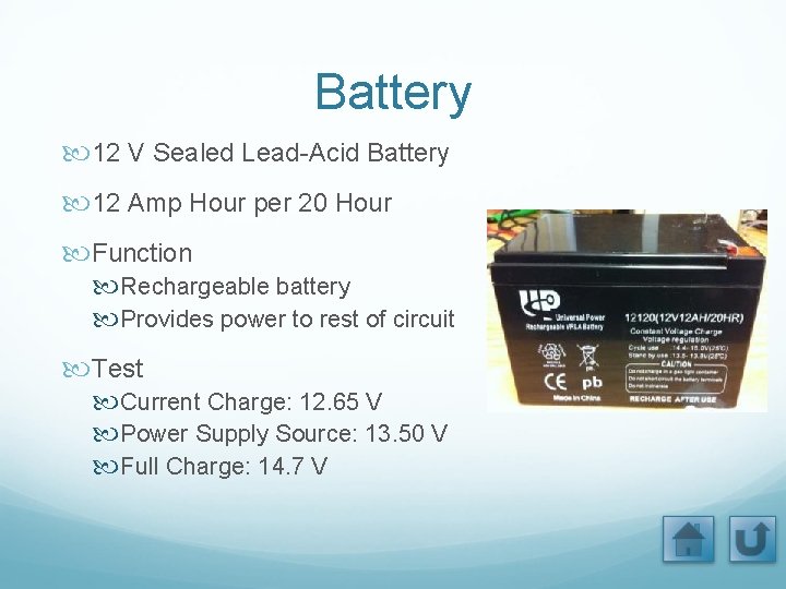
Battery 12 V Sealed Lead-Acid Battery 12 Amp Hour per 20 Hour Function Rechargeable battery Provides power to rest of circuit Test Current Charge: 12. 65 V Power Supply Source: 13. 50 V Full Charge: 14. 7 V
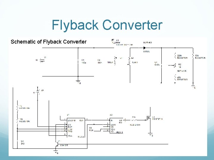
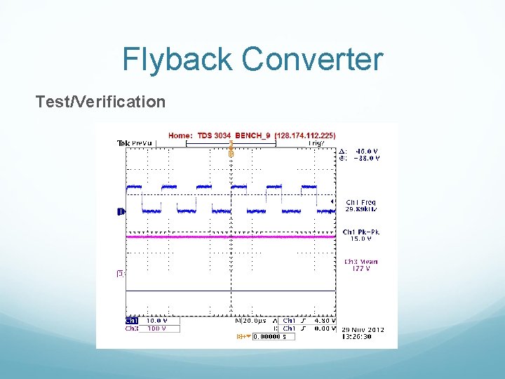
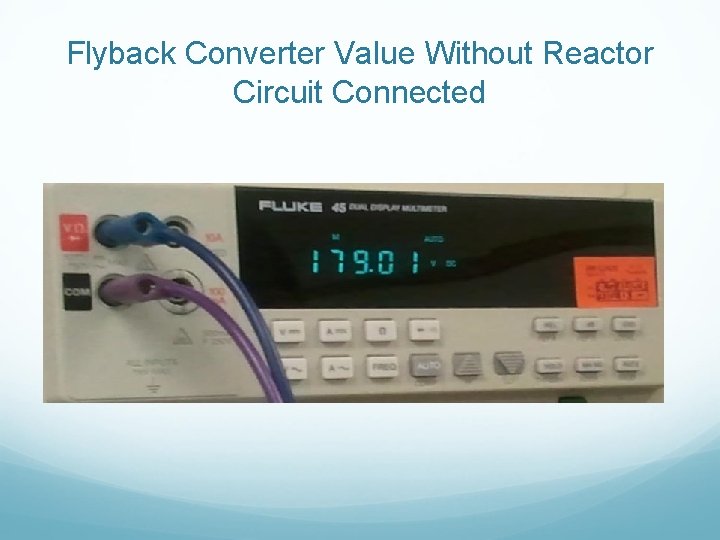
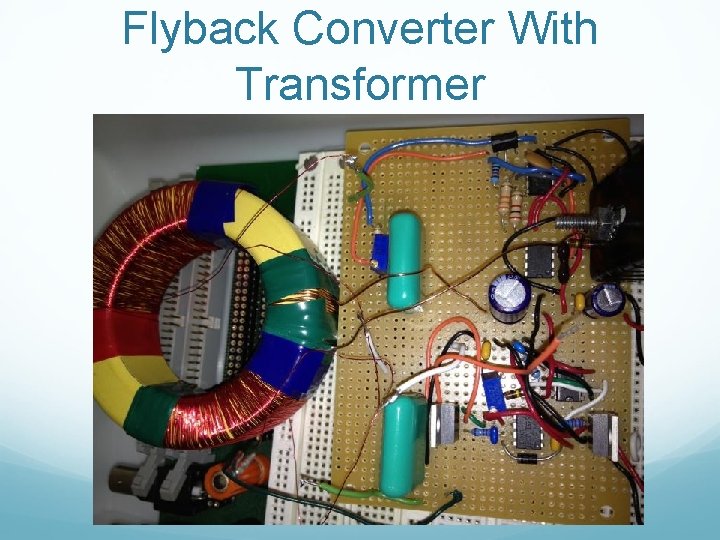
Flyback Converter • Indirect Conversion • Steps up battery voltage Steps 12 V to ~180 V • Duty Cycle of 93% 555 Timer • ~30 k. Hz • Switches NMOS On & Off Ø Charges & Discharges Transformer
Flyback Converter Schematic of Flyback Converter
Flyback Converter Test/Verification
Flyback Converter Value Without Reactor Circuit Connected
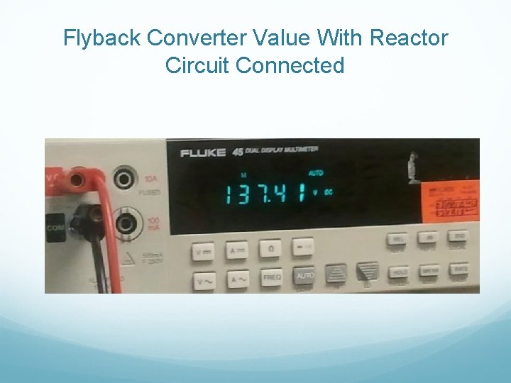
Flyback Converter Value With Reactor Circuit Connected
Flyback Converter With Transformer
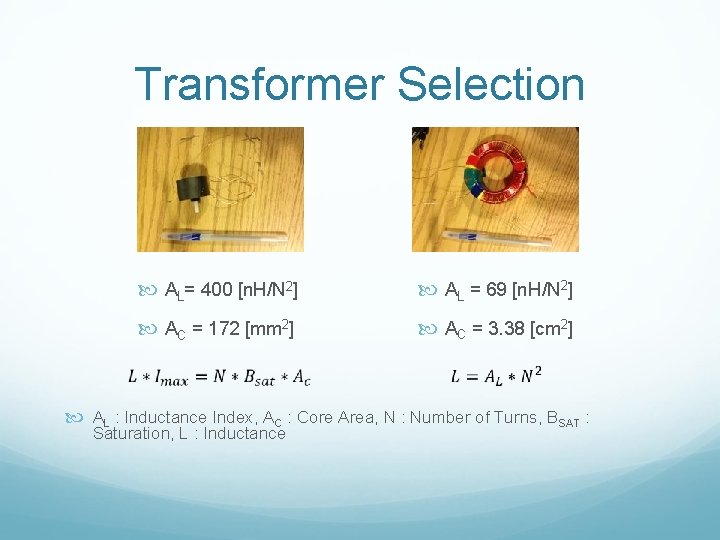
Transformer Selection AL= 400 [n. H/N 2] AL = 69 [n. H/N 2] AC = 172 [mm 2] AC = 3. 38 [cm 2] AL : Inductance Index, AC : Core Area, N : Number of Turns, BSAT : Saturation, L : Inductance
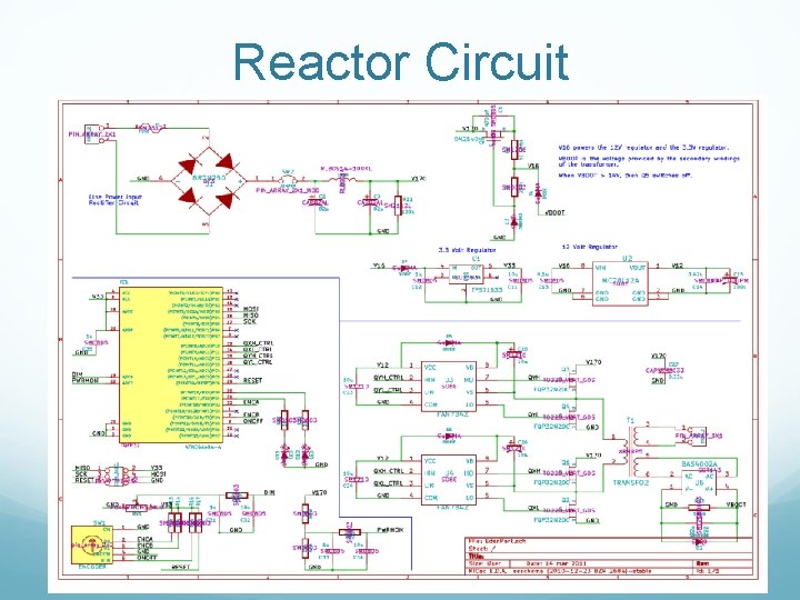
Reactor Circuit Functions Regulates entire circuit for operation Microcontroller • Atmel Atmega 44/88/682545 TS (32 MLF ver. ) Monitors H-Bridge in circuit Produce pulse wave needed to drive reactor Outputs 1 -2 k. V with transformer
Reactor Circuit
Reactor Circuit
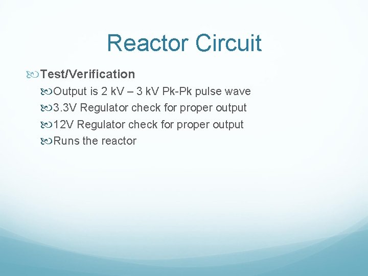
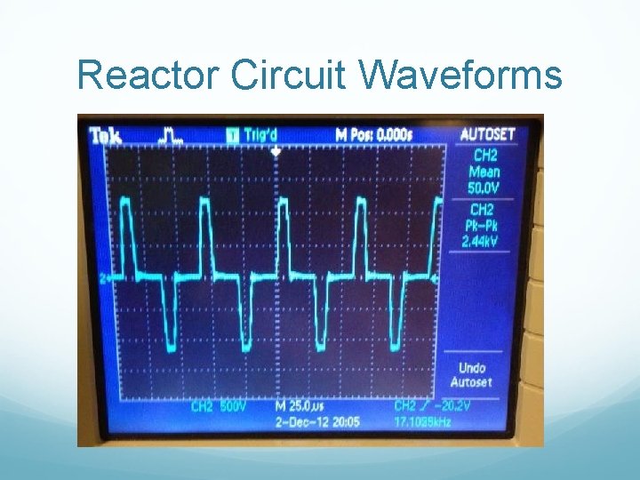
Reactor Circuit Test/Verification Output is 2 k. V – 3 k. V Pk-Pk pulse wave 3. 3 V Regulator check for proper output 12 V Regulator check for proper output Runs the reactor
Reactor Circuit Waveforms
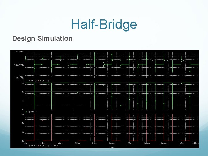
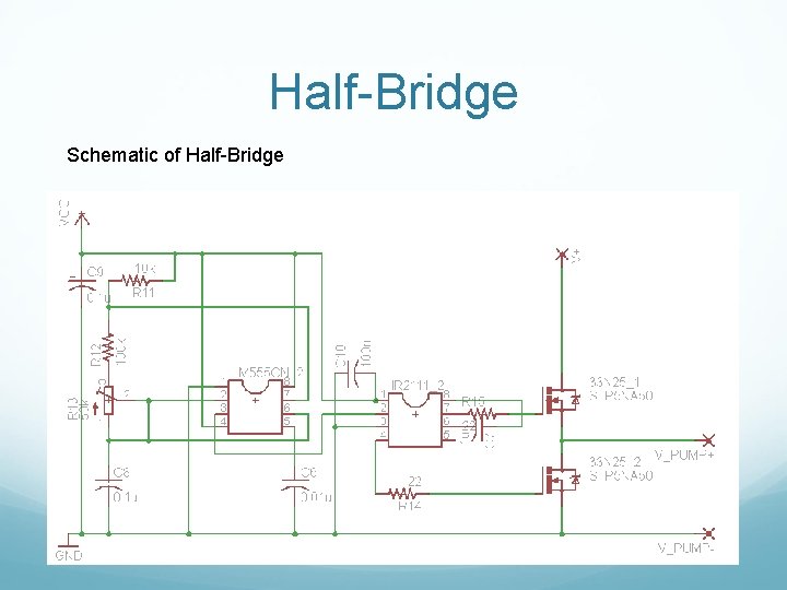
Half-Bridge Converts DC-AC to power pump. Converts Flyback output to 180 V RMS 555 timer for square wave Half-Bridge gate driver
Half-Bridge Design Simulation
Half-Bridge Schematic of Half-Bridge
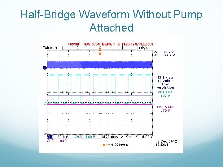
Half-Bridge Waveform Without Pump Attached
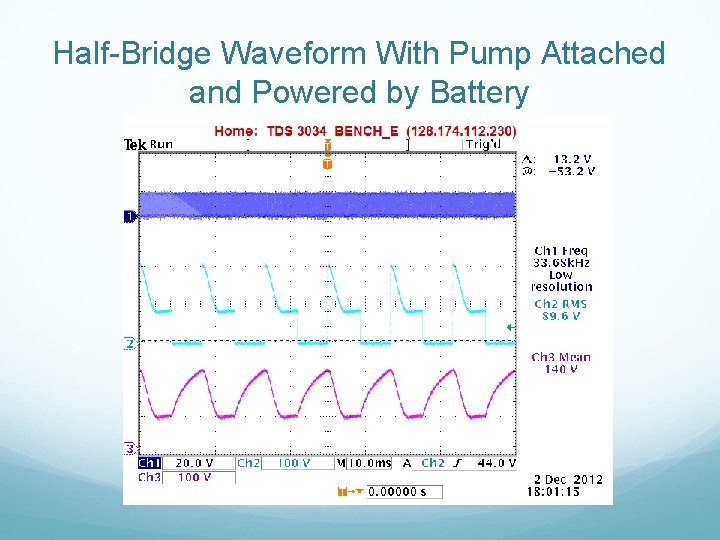
Half-Bridge Waveform With Pump Attached and Powered by Battery
Testing and Optimization Results Lowered supply voltage Decreased airflow Explanation/Solution Load behavior Modeling load for testing Increase supply voltage
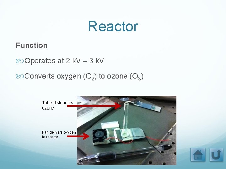
Reactor Function Operates at 2 k. V – 3 k. V Converts oxygen (O 2) to ozone (O 3) Tube distributes ozone Fan delivers oxygen to reactor
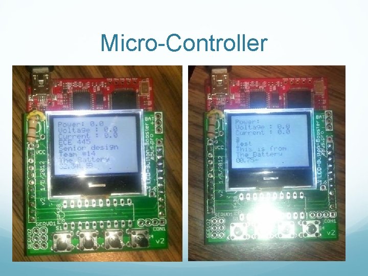
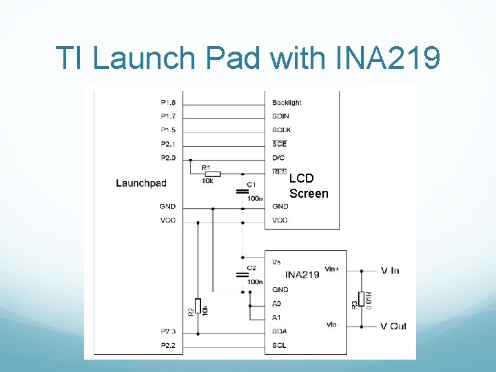
Micro-Controller Texas Instruments Launch Pad MSP 430 Functions Displays Info on LCD • Voltage • Current • Power
Micro-Controller
The Micro-Controller Code Reads in values To Read INA 219 is used Header file used to read in from pins Display values LCD display is used Can’t display “float” To display “float” was split into “int” Example on next page
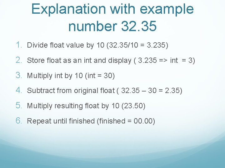
Explanation with example number 32. 35 1. Divide float value by 10 (32. 35/10 = 3. 235) 2. Store float as an int and display ( 3. 235 => int = 3) 3. Multiply int by 10 (int = 30) 4. Subtract from original float ( 32. 35 – 30 = 2. 35) 5. Multiply resulting float by 10 (23. 50) 6. Repeat until finished (finished = 00. 00)
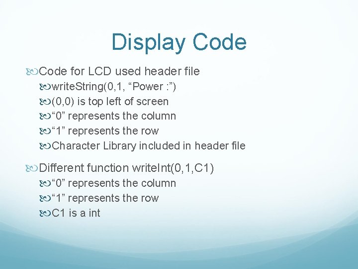
Display Code for LCD used header file write. String(0, 1, “Power : ”) (0, 0) is top left of screen “ 0” represents the column “ 1” represents the row Character Library included in header file Different function write. Int(0, 1, C 1) “ 0” represents the column “ 1” represents the row C 1 is a int
TI Launch Pad with INA 219 LCD Screen
Thank You Professor Gary Eden Professor Park Professor Cho Dr. Cy Herring