SOLAR ENERGY UTILIZATION Solar energy is a very


 Conductors which carry electric")

 High mechanical strength (ii) Light in weight without the loss of")


- Slides: 26
SOLAR ENERGY UTILIZATION Solar energy is a very large, inexhaustible source of energy. The power from the sun intercepted by the earth is approximately 1. 8× 10¹¹ MW
Biomass: Biomass refers to all organic matter except fossil fuels. Biomass energy refers to the energy released when organic matter is eaten, decayed or burnt Biogas: Biogas is the term used to describe the mixture of gases produced during anaerobic digestion. It is also known as methane gas. It mainly consists of CH 4 (methane) of 55 - 65%, CO 2 (carbon dioxide) 30 - 40% and other gases such as H 2, H 2 S, N 2
Uses of biogas: 1. Used for Cooking 2. Used for Heating 3. Used for Lighting 4. Used for running dual fuel engines (80% biogas + 20% diesel) Types of biogas plants: Biogas plants are basically of two types. Floating dome type: In this type the gas holder floats on the top of the digester. Fixed dome type: In this type the gas holder is fixed on the top of the digester
bb bb
bb
WIND ENERGY The wind energy on the earth surface is estimated to be 1. 6 × 10⁷ MW. A wind velocity of over 6. 5 km/h is necessary for the satisfactory operation Applications of wind mills: 1. Generation of power 2. Pumping water for drink 3. irrigation purpose. 4. Grinding grain Single blade wind mill
SOLAR What are solar cells? A solar cell is an electronic device that uses sunlight and turns it directly into electrical energy. Solar cells are often bundled together to make larger units called solar modules, themselves coupled into even bigger units known as solar panels How are solar cells made A solar cell is a sandwich of two different layers of silicon that have been specially treated or doped so they will allow electricity flow through them. The lower layer is doped so it has slightly too few electrons. It's called p -type or positive-type silicon (because electrons are negatively charged and this layer has too few of them). The upper layer is doped the opposite way to give it slightly too many electrons. It's called n-type or negative
When a layer of n-type silicon on a layer of p-type silicon, a barrier is created at the junction of the two materials How do solar cells work 1. When sunlight shines on the cell, photons (light particles) bombard the upper surface. 2. The photons carry their energy down through the cell. 3. The photons give up their energy to electrons (green blobs) in the lower, p-type layer. 4. The electrons use this energy to jump across the barrier into the upper, n-type layer and escape out into the circuit. 5. Flowing around the circuit, the electrons make the electricity/electrical energy.
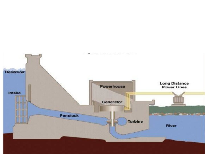
Hydropower Plants Classification of Hydropower Plants According to water flow regulation: 1. Runoff river plants without pondage 2. Runoff river plants with pondage 3. Hydroelectric plants with storage reservoir According to Load 1. Base load plants 2. Peak load plants 3. Pumped storage plants According to head 1. High head plants (>100 m) 2. Medium head plants (30 -100 m) 3. Low head plants (<30 m)
Dam Develops a reservoir to store water, Builds up head for power generation Spillway To safeguard the dam when water level in the reservoir rises Intake Contains trash racks to filter out debris which may damage the turbine Forebay Enlarged body of water just above the intake Headrace is a channel which lead the water to the turbine Tailrace is a channel which carries water from the turbine Penstocks are closed conduits for supplying water “under pressure” from head pond to the turbines. Surge Tank A surge tank is a small reservoir in which the water level rises or falls to reduce the pressure swings so that they are not transmitted to the penstock. Types of Hydraulic Turbines 1. According to the head and quantity of water available a. Low head (2 -15 m) b. Medium head (16 -70 m) c. High head (71 -500 m) d. Very high head (>500 m) 2. According to the name of the originator a. Francis b. Kaplan c. Pelton
POWER TRANSMISSION AND DISTRIBUTION Main Components of Overhead Lines (i) Conductors which carry electric power from the sending end station to the receiving end station. (ii) Supports which may be poles or towers and keep the conductors at a suitable level above the ground. (iii) Insulators which are attached to supports and insulate the conductors from the ground. (iv) Cross arms which provide support to the insulators 1) high electrical conductivity. CONDUCTOR MATERIALS 2) high tensile strength in order to withstand mechanical stresses. 3) low cost so that it can be used for long distances. 4) low specific gravity so that weight per unit volume is small.
COMMONLY USED CONDUCTOR MATERIALS. copper, Aluminium, Steel-cored Aluminium, Galvanised steel and Cadmium Copper It has high electrical conductivity and greater tensile strength Aluminium is cheap and light as compared to copper but it has much smaller conductivity and tensile strength COMMONLY USED CONDUCTOR ON TRANSMISSION AND DISTRIBUTION ARE 1). ACSR Aluminium Conductor Steal Reienforce 2). AAAC All Aluminium Alloy Conductor 3). AAC All Aluminium Conductor 4). ABC Arial Bundled Conductor
LINE SUPPORTS (i) High mechanical strength (ii) Light in weight without the loss of mechanical strength. (iii) Cheap in cost and economical to maintain. (iv) Longer life. COMMON TYPE OF SUPPORTS A. wooden poles B. steel poles C. R. C. C. poles D. steel towers WOODEN POLES (i) tendency to rot below the ground level (ii) comparatively smaller life (20 -25 years) (iii) cannot be used for voltages higher than 20 k. V (iv) less mechanical strength (v) require periodical inspection Steel poles. They have greater mechanical strength, longer life and permit longer spans This type of supports need to be galvanised or painted in order to prolong its life. RCC poles. The reinforced concrete poles They have greater mechanical strength, longer life l spans than steel poles. The holes in the poles facilitate the climbing of poles and at the same time reduce the weight of line supports.
1. Suspension insulator set 2. Phase conductor 3. Spacer between two conductors of the same phase 4. Shield conductor 5. A set of three phase conductors 6. Identification plate 7. Security feature against unauthorised climber
STEEL TOWERS. For long distance transmission at higher voltage, steel towers are employed. Steel towers have greater mechanical strength, longer wooden, steel and reinforced concrete poles are used for distribution purposes at low voltages INSULATORS The overhead line conductors should be supported on the poles or towers in such a way that currents from conductors do not flow to earth through supports (i) High mechanical strength (ii) High electrical resistance of insulator material in order to avoid leakage currents to earth. (iii) High dielectric strength (iv) The insulator material should be free from cracks otherwise the permittivity will be lowered TYPES OF INSULATORS 1. Pin type insulators 2. Suspension type insulators
Strain insulators Post insulators made of porcelain Shackle insulators
SKIN EFFECT The phenomena arising due to unequal distribution of current over the entire cross section of the conductor being used for long distance power transmission is referred as the skin effect in transmission lines. FERRANTI EFFECT In all practical cases the sending end voltage is higher than the receiving end, so current flows from the source or the supply end to the load. ASTONISHING THEORY ABOUT MEDIUM OR LONG DISTANCE TRANSMISSION LINES suggesting that in case of light loading or no load operation of transmission system, the receiving end voltage often increases beyond the sending end voltage, leading to a phenomena known as Ferranti effect in power system WHY FERRANTI EFFECT OCCURS IN A TRANSMISSION LINE? A long transmission line can be considered to composed a considerably high amount of capacitance and inductance distributed across the entire length of the line. FERRANTI EFFECT OCCURS WHEN current drawn by the distributed capacitance of the line itself is greater than the current associated with the load at the receiving end of the line( during light or no load). Receiving end voltage tends to get larger than applied voltage leading to the phenomena called Ferranti effect
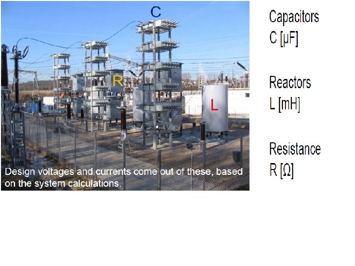
TRANSMISSION LINE PARAMETERS The electric parameters of transmission lines Resistance, inductance, and capacitance THE TRANSMISSION LINES ARE CATEGORIZED AS THREE TYPES 5) Short transmission line – the line length is up to 80 km 6) Medium transmission line – the line length is between 80 km to 230 km 7) Long transmission line – the line length is more than 230 km
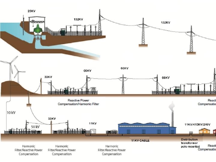
PRIMARY AND SECONDARY DISTRIBUTION NETWORK PRIMARY DISTRIBUTION SYSTEMS The primary distribution is universally carried out by 3 -phase 3 -wire system. SECONDARY DISTRIBUTION SYSTEM Electric power from the generating station is transmitted through HV lines to various substations located near the load centre