SOLAR COMPOUND PARABOLIC CONCENTRATOR TROUGHS PART I Parabolic

SOLAR COMPOUND PARABOLIC CONCENTRATOR TROUGHS

PART I

Parabolic dish prototype use in the solar thermal cogeneration

Schematic of a parabolic dish concentrator .

Characteristics of spherical optics

Off-axis light reflection from parabolic mirror

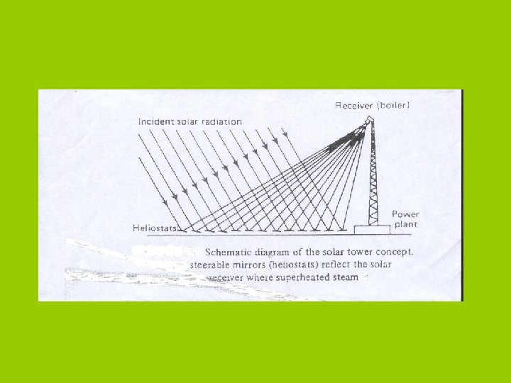
Schematic of a power tower

Parabolic TROUGHS

Schematic of a parabolic trough concentrator

__ In case of dishes: Rays parallel to the axis are reflected to the point, called Point Focus Concentrator. __ in case of Parabolic Trough rays parallel to its axis are reflected to focal line, called Line – Focus Concentrator. __ In case of Compound Parabolic Concentrator, Concentrates rays not necessarely parallel or aligned to its axis. ( non imaging concentrator. ) __Half of the PC which is pointing away of the sun is replace by another half that can be in position pointing to the sun, then both halves will reflect rays to a point below the focal point, ( CPC is produced)

Kinds of dishes. 1 - Spherical 2 - Compound Parabolic concentrator, CPC. 3 - Fixed mirror solar concentrator, FMSC 4 -- Fixed mirror defuse form, FMDF 5 -- Slate, changing reflector fixed receiver, .
. 2 - Parabolic trough collector, (PTC)")
Kinds of troughs. 1 - cylidrical trough, (CT). 2 - Parabolic trough collector, (PTC) 3 - Compound Parabolic concentrator, (CPC).

PART II
: -- Also called as line-focus concentrators -- Why Parabolic? The incident")
PARABOLIC TROUGH COLLECTORS(PTC): -- Also called as line-focus concentrators -- Why Parabolic? The incident radiation should bisect at the contact point and be tangent to the receiver Tube which can be obtained by using the profile of a parabola.


Troughs are Reliable, Proven, and Performance Is High

trough subsystem - half drive string. Courtesy of Sandia National Laboratories.

Solar Aperture Area Illustration for parabolic concentrators

Euro. Trough initial remarks Concentrating Parabolic Trough Collector for solar. . . 1 - electricity generation 2 - desalination 3 - process heat Outlet temperature 400°C (752°F) Collector size 545 m^2 - 817 m^2 up to 650 k. W thermal output per collector Electricity price ranges 15 cts/k. Wh Technology under commercial operation in California (Mojave Desert, 354 MWel)

Schematic of a solar thermal power plant

The Euro. Trough Prototype
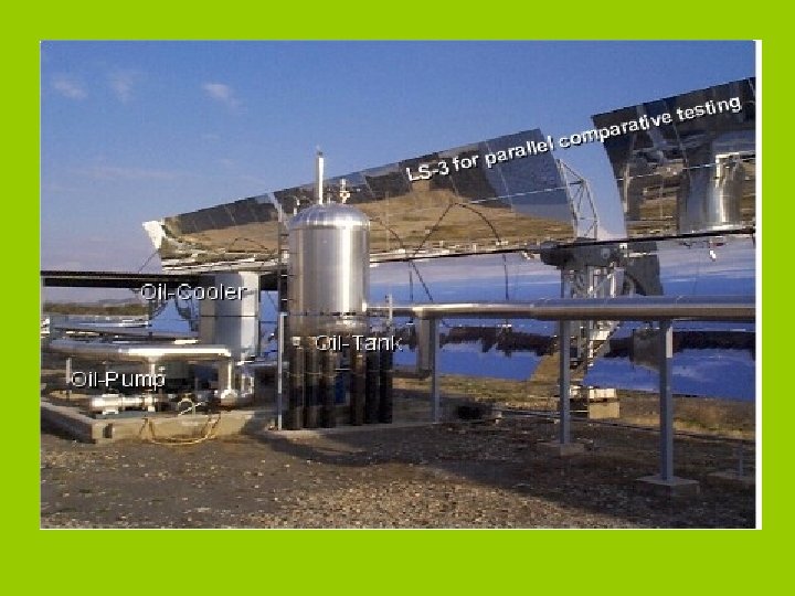

Euro. Trough Characteristics Layout parabolic trough collector -- support structure steel frame work, pre-galvanized, three variants; light weight, low torsion -- collector length 12 m per element; 100 - 150 m collector length -- drive: hydraulic drive -- max. wind speed operation: 14 m/s, stow: 40 m/s -- Tracking control clock + sun sensor, <2 mrad -- Parabola: y = x 2/4 f with f = 1. 71 m -- aperture width: 5. 8 m -- Reflector : 4 glass facets -- optical efficiency: 0. 80 (design) -- absorber tube evacuated glass envelope, UVAC® or other, application dependent -- Fluid oil, steam, application dependent -- cost < 200 Euro/m 2

Euro. Trough performance thermal testing at PSA -- with oil loop up to 390°C in east-west orientation (normal incident radiation once a day) -- influence of : - fluid temperature -solar radiation (direct normal) -incidence angle -- photogrammetry -- mechanical analyses Receiver Reflector

SOLAR CONCENTRATION MATHEMATICAL MODELING: 1 - REFLECTOR of APERTURE AREA, Aa 2 - RECEIVER OF AREA, (Collector) Ar -- CONCENTRATION RATIO: CR=Aa/Ar
= q X Aa X ρa(τα)r Solar heat")
Solar heat quantity arriving the receiver, (Q)= q X Aa X ρa(τα)r Solar heat quantity used by the receiver, (Qu)= q X Aa X ρa(τα)r– Ql Ql is the losses. The solar efficiency ζs = (Q – Ql )/ (q. XAa) = ρa(τα)r[1 – Ql/ ρa(τα)r (q. XAa)]

Losses will be: where: hg = convective heat-transfer coefficient at outside surface of glass envelope (W/m 2 °C) Ag = outside surface of glass envelope (m 2) Tg = outside surface temperature of glass envelope (K) Ta = ambient temperature (K) σΒ = Stefan-Boltzmann constant (5. 6696 × 10 -8 W/m 2 K 4 ) ε g= emittance of the glass Fga = radiation shape factor Ts = sky temperature (K) Aq = Ar, hq = Ur, Tq = Tr
 Assuming")
For Concentration Ratio Less than 10: Ql = Ur Ar (Tr – Ta) Assuming a steam turbine engine that works by Carnot Cycle, Thermal Eff: ζth = (Tr – Ta)/Tr Then over all Efficiency, ζov = ζth X ζs = [ρa(τα)r Tr] [ ΔT- Ur. X ΔT^2/ ρa(τα)r q CR] Max. ζov occurs at, Tr = √ [ (q CR ρa(τα)r /Ur + Ta ) Ta]

EXAMPLE: Desert at 32 North, Jordan, average q=800 W/m^2, Ta=305, Two collectors 1 st. Flat plate, (CR=1), Ur=5 W/K. m 2, (τα)=0. 8 2 nd. CPC, CR=3, Ur = 2 W/K. m^2. ρ = 0. 9, (τα)=0. 8. Calculate max. conditions. Solution: Using equations in last slide: 1 - Flat plate, Tr= 363. 5 K, ζth = 16. 1%, ζs=43% and ζov=7% 2 - CPC, (CR=3) Tr= 597 K, ζth= 49%, ζs=45% and ζov=22%
r – εб Ar (Tr^4 –")
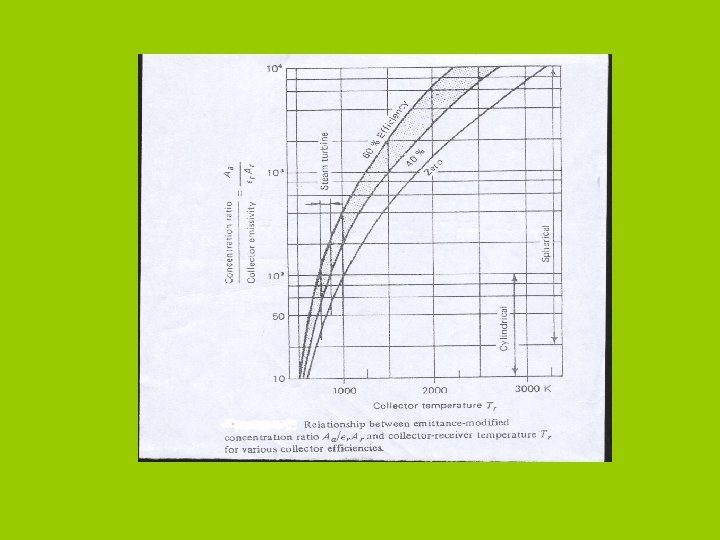
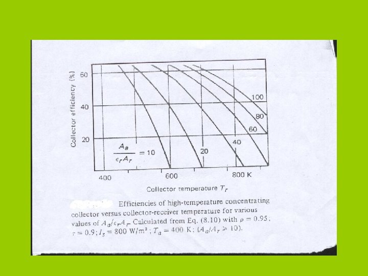
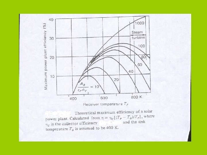
FOR CR > 10: Qu = Aa q ρa(τα)r – εб Ar (Tr^4 – Ta^4) And Solar efficiency, ζs = ρa(τα)r – εб (Tr^4 – Ta^4)/q CR Control parameters are: CR/ ε and Tr ζov =[( Tr – Ta) / Tr] ζs

Performance of prototype parabolic trough

Comparison of experimentally measured ΔT/I curves with flatplate collector performance

Annual performance summary of flat-plate, parabolic trough and parabolic dish collectors.

PART III

STEAM AS TROUGH WORKING FLUID:

DESIGN CONSIDERATIONS: 1 - To reduce the heat loss due to convection and conduction, the space between absorber and cover is evacuated. 2 - The absorber is painted with a high absorptance paint. 3 - Cover material is selected to have high transmittance. A reflective coating is also applied on the inside of the cover to reflect the radiation back onto the absorber.

MODEL PARAMETERS Width of the collector: 4 m Concentration Ratio: 50 Diameter of Cover tube: 0. 06 m Mass flow rate in collector loop: 0. 04 kg/s Mass flow rate in load loop: 0. 03 kg/s Material of tube: Stainless steel

RESULTS
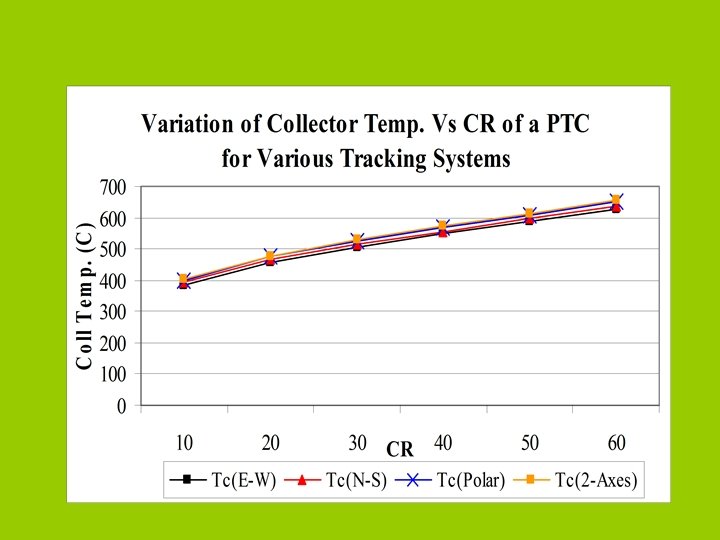

RESULTS CR = 50, W = 4 m and L=20 m

RESULTS CR = 50, W = 4 m and L = 20 m

CONCLUSION -- From the results we can see that these systems can be used to generate steam for various applications. -- The best system seems to be the one that is tracked along the polar axes.

PART IV

CPC: _ Rays parallel to the axis are reflected to the point, called Point Focus Concentrator. __ in case of Parabolic Trough rays parallel to its axis are reflected to focal line, called Line – Focus Concentrator. __ In case of Compound Parabolic Concentrator, rays no need to be parallel or aligned with the axis, called Non – Imaging Concentrator __Half of the PC which is pointing away of the sun is replace by another half that can be in position pointing to the sun, then both halves will reflect rays to a point below the focal point, ( CPC is produced)
.")
Compound Parabolic Concentrator The compound parabolic concentrator (CPC).
![ζs = 0. 73 – 0. 64 [ (Tr-Ta) / q ] Tilt](http://slidetodoc.com/presentation_image/25fea73cbd68c9eb671982c018fe73d7/image-48.jpg "ζs = 0. 73 – 0. 64 [ (Tr-Ta) / q ] Tilt")
ζs = 0. 73 – 0. 64 [ (Tr-Ta) / q ] Tilt Requirements of CPCs with Different Acceptance Angles Average Shortest Collection Number of Period Time if Tilt Acceptance Time Average Adjustments Without Adjusted Half -Angle over Year per Year Adjustment Every Day (h/day) (days) (h/day) 19. 5º 9. 22 2 180 10. 72 14º 8. 76 4 35 10. 04 11º 8. 60 6 35 9. 52 9º 8. 38 10 24 9. 08 8º 8. 22 14 16 8. 82 7º 8. 04 20 13 8. 54 6. 5º 7. 96 26 9 8. 36 6º 7. 78 80 1 8. 18 5. 5º 7. 60 84 1 8. 00

CPC tracking system

Tracking Controller control/monitor shades the other . Solargen. org
 receiver. Courtesy of Sandia National Laboratories.")
Cavity (focal plane) receiver. Courtesy of Sandia National Laboratories.

Logic flow for computing receiver heat loss - glass envelope.

. Optimization of the collector receiver size.

Annual performance summary of the collector concepts discussed above.

PART V PV systems

PV Systems to power the circulation pump.

SYDTEM COMPONENTS: 1 - MODULES, Electricity generators. 2 - Batteries - store electricity to provide energy on demand at night or on overcast days; 3 - Inverters - required to convert the DC power produced by the PV module into AC power; 4 - Controllers - manage the energy storage to the battery and deliver power to the load; and 5 - Structure - required to mount or install the PV modules and other components. 6 - Not all systems will require all these components.

Crystalline Silicon Solar Cell.

Grid-Connected PV System Schematic [adapted from Ross and Royer, 1999
![Stand-Alone Off-Grid PV System Schematic [adapted from Ross and Royer, 1999].](http://slidetodoc.com/presentation_image/25fea73cbd68c9eb671982c018fe73d7/image-63.jpg "Stand-Alone Off-Grid PV System Schematic [adapted from Ross and Royer, 1999].")
Stand-Alone Off-Grid PV System Schematic [adapted from Ross and Royer, 1999].
![Water Pumping PV System Schematic [adapted from Ross and Royer, 1999].](http://slidetodoc.com/presentation_image/25fea73cbd68c9eb671982c018fe73d7/image-64.jpg "Water Pumping PV System Schematic [adapted from Ross and Royer, 1999].")
Water Pumping PV System Schematic [adapted from Ross and Royer, 1999].

APPLICATIONS. 1 - On-grid applications, which cover both central-grid and isolated-grid systems; 2 - Off-grid applications, which include both standalone (PV-battery) systems 3 - and hybrid (PV-battery-genset) systems; and Water pumping applications, which include PV-pump systems.

Systems may be divided into three types: 1 - Stand-alone systems - those systems which use photovoltaics technology only, and are not connected to a utility grid. 2 - Hybrid systems - those systems which use photovoltaics and some other form of energy, such as diesel generation or wind. 3 - Grid-tied systems - those systems which are connected to a utility grid.

PV CALCULATIONS: Given: Power required per day at highest conditions. =P k. W/d. Solar Power required daily = Pxζc ζb ζe Solar intensity at lowest conditions, peak value=800 W/m^2, Sinusoidal shape, for 9 hours, Wp at peak value. Daily power value per module = (Wp/√ 2)(0. 7 x 9) Wh Number of modules= Pxζc ζb ζe/ (Wp/√ 2)(0. 7 x 9) Power Stored in the batteries = (0. 7 x 9) [Wp(1 -1/ √ 2)] Wh Hours.

THANK YOU
- Slides: 68