
Soft Xray SelfSeeding Philip Heimann SLAC Daniele Cocco
- Slides: 14
Soft X-ray Self-Seeding Philip Heimann (SLAC) Daniele Cocco, Juhao Wu, Jim Welch, Yiping Feng, John Amann, Zhirong Huang, Jerry Hastings (SLAC) Paul Emma (LBNL) SLAC/LBNL R&D project in Soft X-ray Self Seeding
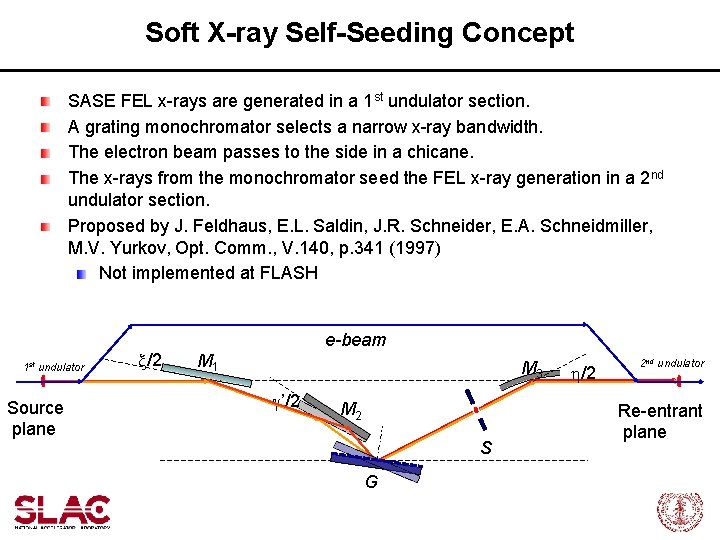
Soft X-ray Self-Seeding Concept SASE FEL x-rays are generated in a 1 st undulator section. A grating monochromator selects a narrow x-ray bandwidth. The electron beam passes to the side in a chicane. The x-rays from the monochromator seed the FEL x-ray generation in a 2 nd undulator section. Proposed by J. Feldhaus, E. L. Saldin, J. R. Schneider, E. A. Schneidmiller, M. V. Yurkov, Opt. Comm. , V. 140, p. 341 (1997) Not implemented at FLASH 1 st undulator Source plane x/2 e-beam M 1 M 3 g’/2 M 2 S G h/2 2 nd undulator Re-entrant plane
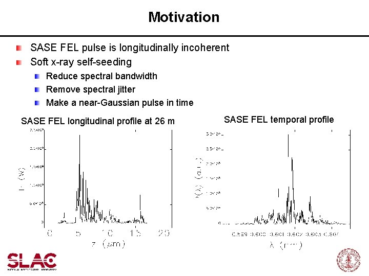
Motivation SASE FEL pulse is longitudinally incoherent Soft x-ray self-seeding Reduce spectral bandwidth Remove spectral jitter Make a near-Gaussian pulse in time SASE FEL longitudinal profile at 26 m SASE FEL temporal profile
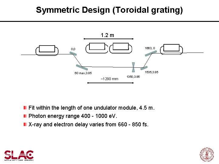
Symmetric Design (Toroidal grating) 1. 2 m 1663, 0 0, 0 1535, 3. 85 60 max, 3. 85 ~1290 mm 1350, 3. 85 Fit within the length of one undulator module, 4. 5 m. Photon energy range 400 - 1000 e. V. X-ray and electron delay varies from 660 - 850 fs.
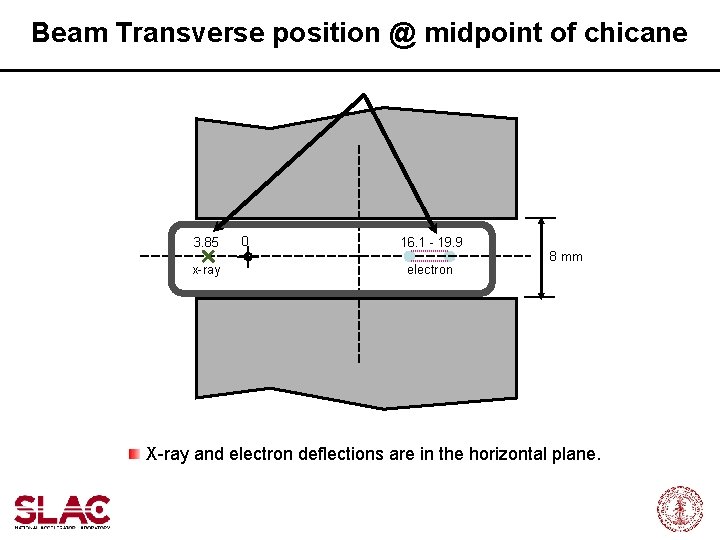
Beam Transverse position @ midpoint of chicane 3. 85 x-ray 0 16. 1 - 19. 9 electron 8 mm X-ray and electron deflections are in the horizontal plane.
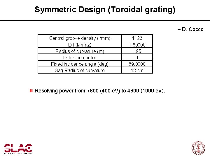
Symmetric Design (Toroidal grating) – D. Cocco Central groove density (l/mm) D 1 (l/mm 2) Radius of curvature (m) Diffraction order Fixed incidence angle (deg) Sag Radius of curvature 1123 1. 60000 195 1 89. 0000 18 cm Resolving power from 7800 (400 e. V) to 4800 (1000 e. V).
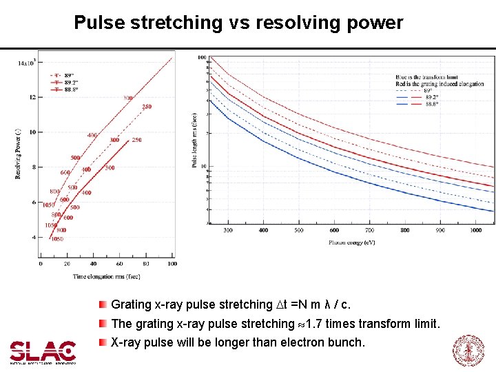
Pulse stretching vs resolving power Grating x-ray pulse stretching Dt =N m λ / c. The grating x-ray pulse stretching 1. 7 times transform limit. X-ray pulse will be longer than electron bunch.
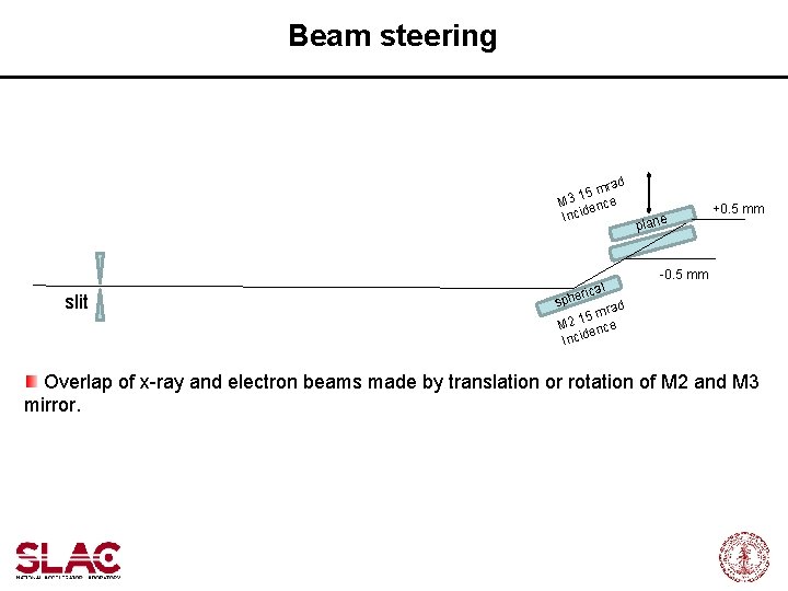
Beam steering d ra 15 m e 3 M c den Inci slit cal heri plane +0. 5 mm -0. 5 mm sp rad 15 m e 2 M c den i c n I Overlap of x-ray and electron beams made by translation or rotation of M 2 and M 3 mirror.
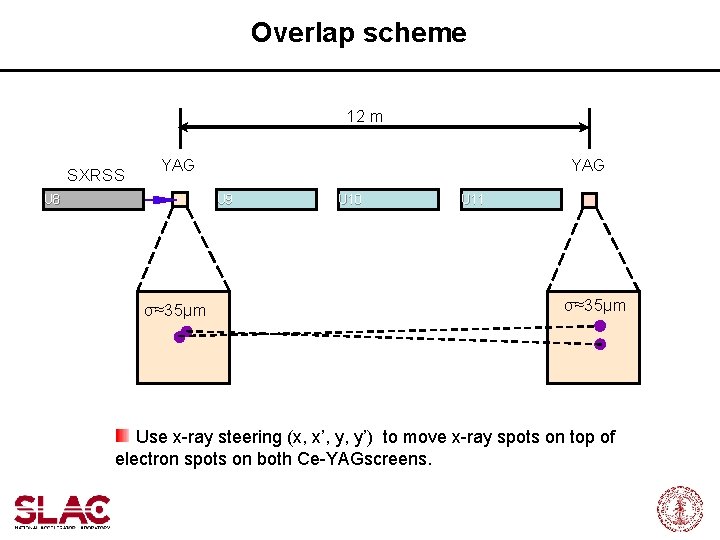
Overlap scheme 12 m SXRSS YAG U 8 YAG U 9 σ≈35μm U 10 U 11 σ≈35μm Use x-ray steering (x, x’, y, y’) to move x-ray spots on top of electron spots on both Ce-YAGscreens.
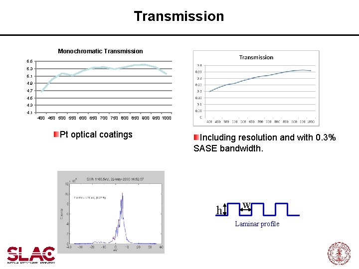
Transmission Monochromatic Transmission 5. 5 5. 3 5. 1 4. 9 4. 7 4. 5 4. 3 4. 1 400 450 500 550 600 650 700 750 800 850 900 950 1000 Pt optical coatings Including resolution and with 0. 3% SASE bandwidth. h w Laminar profile
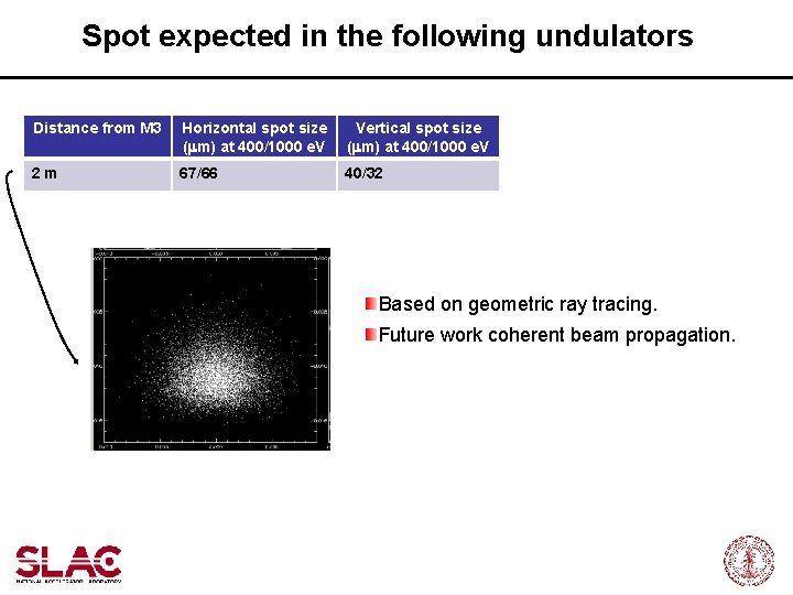
Spot expected in the following undulators Distance from M 3 Horizontal spot size (mm) at 400/1000 e. V Vertical spot size (mm) at 400/1000 e. V 2 m 67/66 40/32 Based on geometric ray tracing. Future work coherent beam propagation.
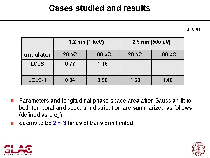
Cases studied and results – J. Wu 1. 2 nm (1 ke. V) undulator 20 p. C 100 p. C LCLS 0. 77 1. 18 LCLS-II 0. 94 0. 98 2. 5 nm (500 e. V) 20 p. C 100 p. C 1. 69 1. 48 Parameters and longitudinal phase space area after Gaussian fit to both temporal and spectrum distribution are summarized as follows (defined as stsw) Seems to be 2 ~ 3 times of transform limited
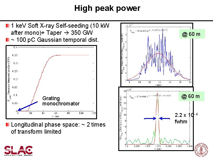
High peak power 1 ke. V Soft X-ray Self-seeding (10 k. W after mono)+ Taper 350 GW ~ 100 p. C Gaussian temporal dist. @ 60 m U 33 Grating monochromator Longitudinal phase space: ~ 2 times of transform limited @ 60 m 2. 2 x 10 -4 fwhm
Summary At the LCLS soft x-ray self-seeding is possible in the length of one undulator module. The optical-electron design is nearly complete. This project is a collaboration between SLAC and LBNL.