
Soft Shadow Volumes for Ray Tracing Samuli Laine


- Slides: 34
Soft Shadow Volumes for Ray Tracing Samuli Laine Timo Aila Helsinki University of Technology, Hybrid Graphics Ltd. Ulf Assarsson Jaakko Lehtinen Tomas Akenine. Möller ARTIS, GRAVIR /IMAG INRIA, Chalmers University of Technology Helsinki University of Technology, Remedy Entertainment Ltd. Lund University
We present An algorithm for computing Soft Shadows • • For planar area light sources Exactly the same shadows as using shadow rays Faster - up to 2 orders of magnitude Can compute very high resolution soft shadows with low extra cost – E. g. allows for 1000 shadow samples per pixel • Requires computation of silhouettes – Trivial for polygon-based scenes
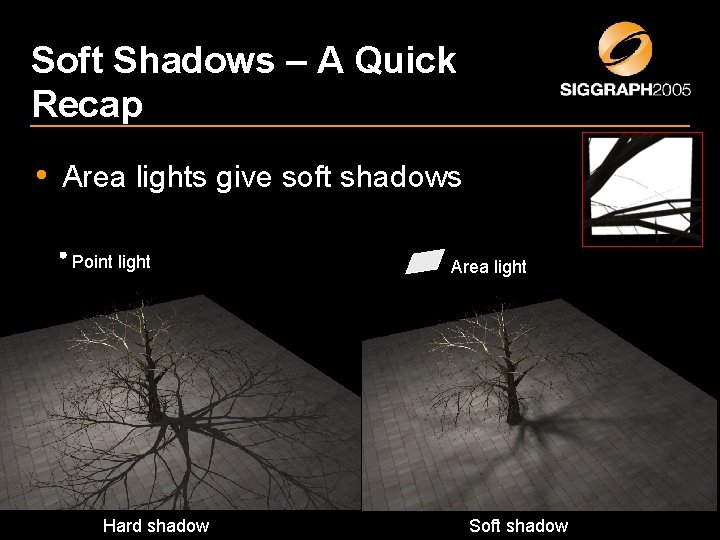
Soft Shadows – A Quick Recap • Area lights give soft shadows Point light Hard shadow Area light Soft shadow
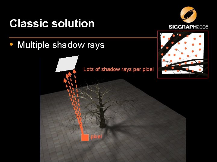
Classic solution • Multiple shadow rays Lots of shadow rays per pixel
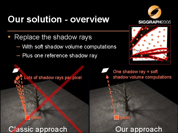
Our solution - overview • Replace the shadow rays – With soft shadow volume computations – Plus one reference shadow ray Lots of shadow rays per pixel Classic approach One shadow ray + soft shadow volume computations pixel Our approach
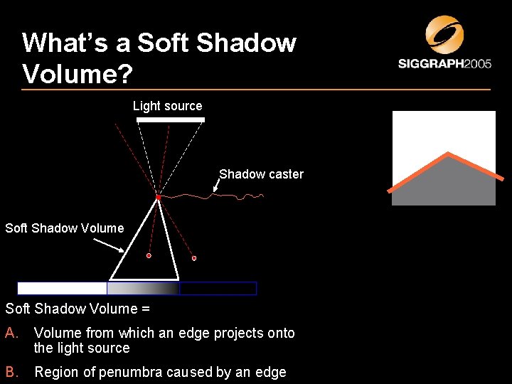
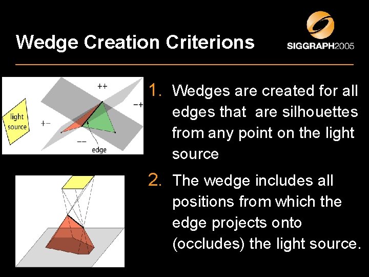
What’s a Soft Shadow Volume? Light source Shadow caster Soft Shadow Volume = A. Volume from which an edge projects onto the light source B. Region of penumbra caused by an edge
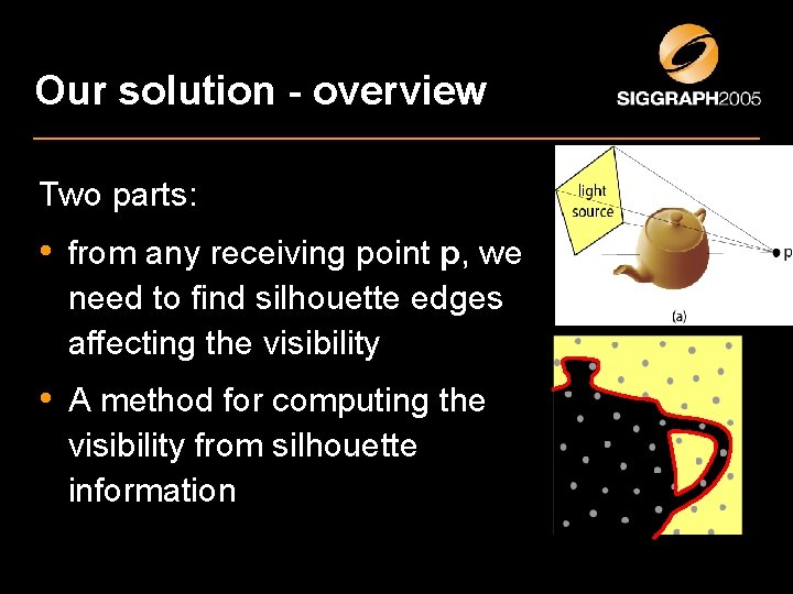
Our solution - overview Two parts: • from any receiving point p, we need to find silhouette edges affecting the visibility • A method for computing the visibility from silhouette information
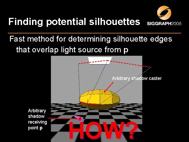
Finding potential silhouettes Fast method for determining silhouette edges that overlap light source from p Arbitrary shadow caster Arbitrary shadow receiving point p HOW?
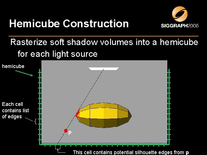
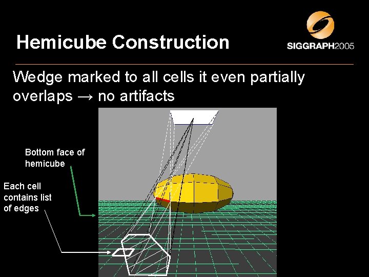
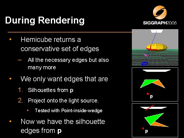
Hemicube Construction Rasterize soft shadow volumes into a hemicube for each light source hemicube Bottom face of hemicube Each cell contains list of edges p This cell contains potential silhouette edges from p
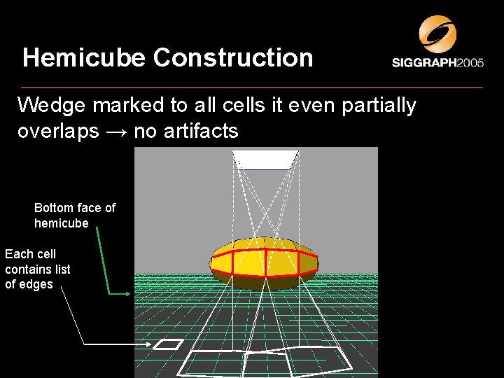
Hemicube Construction Rasterize soft shadow volumes a hemicube Wedge marked to all cells it eveninto partially overlaps →light no artifacts for each source Bottom face of hemicube Each cell contains list of edges
Hemicube Construction Wedge marked to all cells it even partially overlaps → no artifacts Bottom face of hemicube Each cell contains list of edges
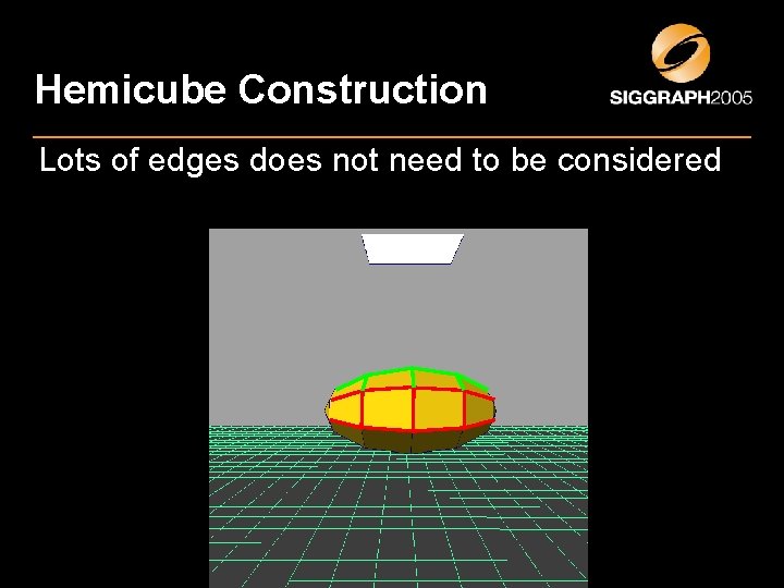
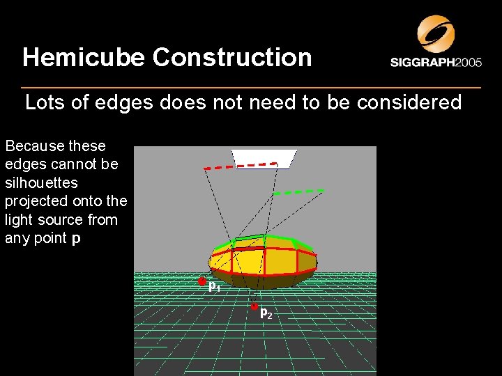
Hemicube Construction Lots of edges does not need to be considered
Hemicube Construction Lots of edges does not need to be considered Because these edges cannot be silhouettes projected onto the light source from any point p p 1 p 2
Wedge Creation Criterions 1. Wedges are created for all edges that are silhouettes from any point on the light source 2. The wedge includes all positions from which the edge projects onto (occludes) the light source.
During Rendering • Hemicube returns a conservative set of edges – • All the necessary edges but also many more We only want edges that are 1. Silhouettes from p p 2. Project onto the light source. • • Tested with Point-inside-wedge Now we have the silhouette edges from p p
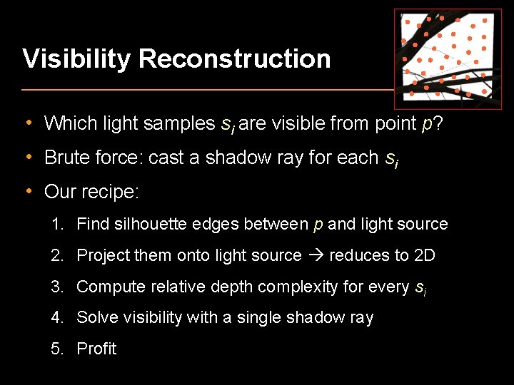
Visibility Reconstruction • Which light samples si are visible from point p? • Brute force: cast a shadow ray for each si • Our recipe: 1. Find silhouette edges between p and light source 2. Project them onto light source reduces to 2 D 3. Compute relative depth complexity for every si 4. Solve visibility with a single shadow ray 5. Profit
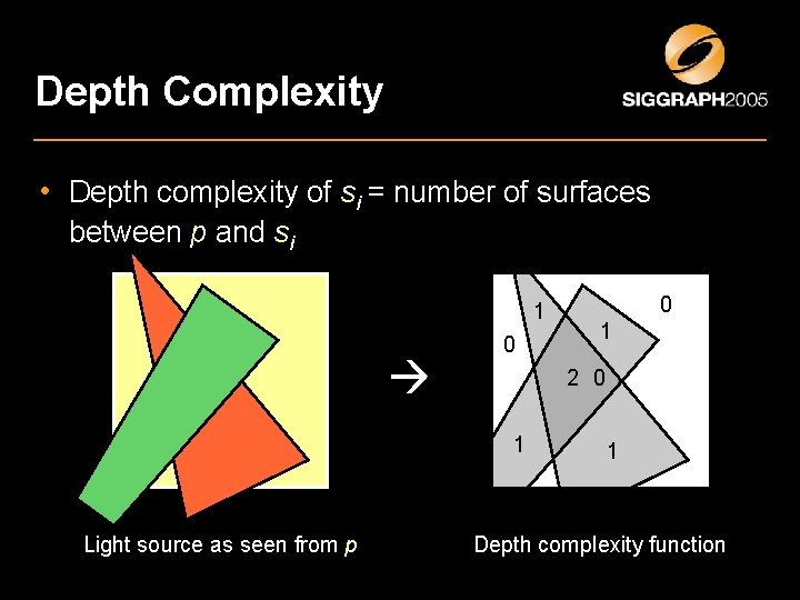
Depth Complexity • Depth complexity of si = number of surfaces between p and si 1 0 1 2 0 1 Light source as seen from p 0 1 Depth complexity function
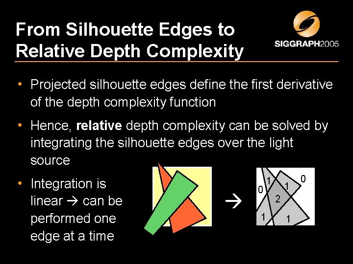
From Silhouette Edges to Relative Depth Complexity • Projected silhouette edges define the first derivative of the depth complexity function • Hence, relative depth complexity can be solved by integrating the silhouette edges over the light source • Integration is linear can be performed one edge at a time 0 1 1 1 2 1 0
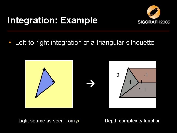
Integration: Example • Left-to-right integration of a triangular silhouette 0 Light source as seen from p -1 10 +1 1 1 -1 Depth complexity function
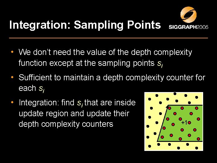
Integration: Sampling Points • We don’t need the value of the depth complexity function except at the sampling points si • Sufficient to maintain a depth complexity counter for each si • Integration: find si that are inside update region and update their depth complexity counters +1
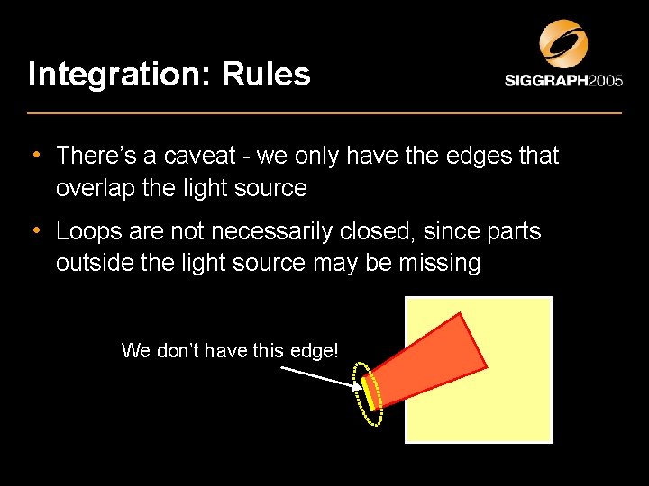
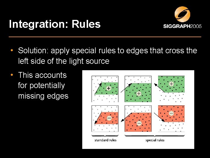
Integration: Rules • There’s a caveat - we only have the edges that overlap the light source • Loops are not necessarily closed, since parts outside the light source may be missing We don’t have this edge!
Integration: Rules • Solution: apply special rules to edges that cross the left side of the light source • This accounts for potentially missing edges
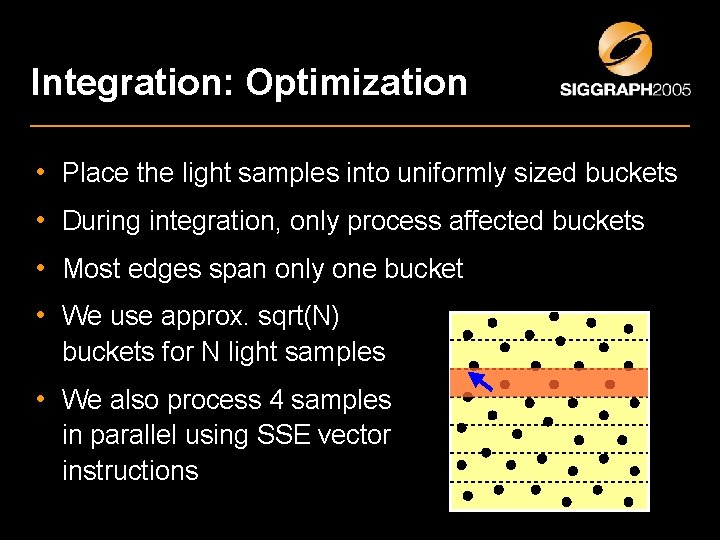
Integration: Optimization • Place the light samples into uniformly sized buckets • During integration, only process affected buckets • Most edges span only one bucket • We use approx. sqrt(N) buckets for N light samples • We also process 4 samples in parallel using SSE vector instructions
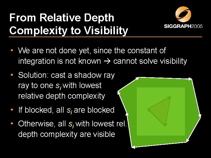
From Relative Depth Complexity to Visibility • We are not done yet, since the constant of integration is not known cannot solve visibility • Solution: cast a shadow ray to one si with lowest relative depth complexity • If blocked, all si are blocked • Otherwise, all si with lowest rel. depth complexity are visible
Experimental Results • Comparisons done using a commercial ray tracer – Turtle by Illuminate Labs – Enabled heuristic shadow ray casting: stop if first 50% of rays agree • Our method was implemented into this ray tracer – We use the same ray caster for casting the reference ray
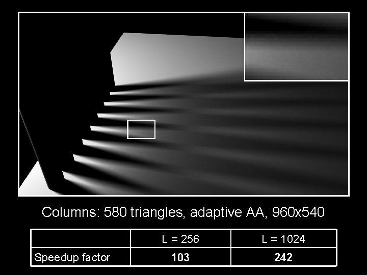
Columns: 580 triangles, adaptive AA, 960 x 540 Speedup factor L = 256 L = 1024 103 242
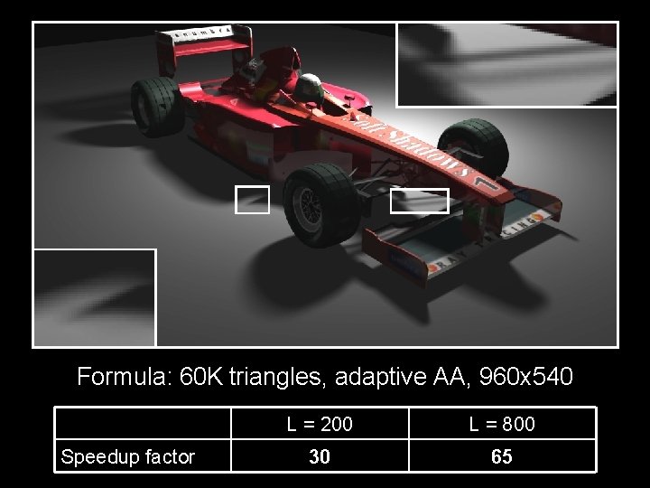
Formula: 60 K triangles, adaptive AA, 960 x 540 Speedup factor L = 200 L = 800 30 65
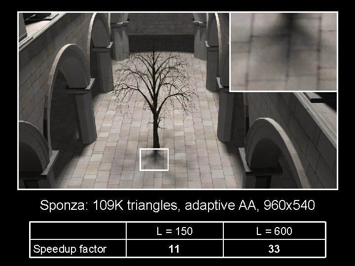
Sponza: 109 K triangles, adaptive AA, 960 x 540 Speedup factor L = 150 L = 600 11 33
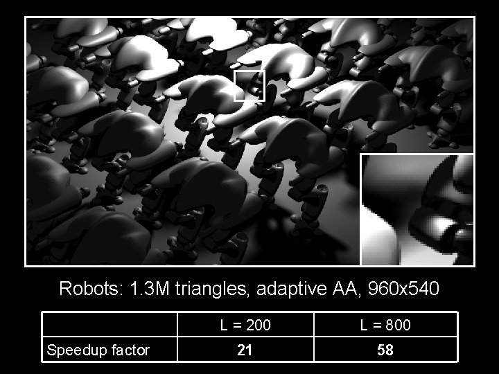
Robots: 1. 3 M triangles, adaptive AA, 960 x 540 Speedup factor L = 200 L = 800 21 58
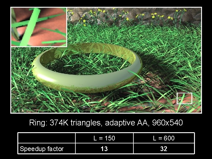
Ring: 374 K triangles, adaptive AA, 960 x 540 Speedup factor L = 150 L = 600 13 32
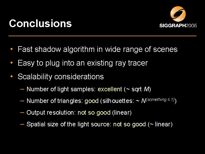
Conclusions • Fast shadow algorithm in wide range of scenes • Easy to plug into an existing ray tracer • Scalability considerations – Number of light samples: excellent (~ sqrt M) – Number of triangles: good (silhouettes: ~ N(something ≤ 1)) – Output resolution: not so good (linear) – Spatial size of the light source: not so good (~ linear)
Future Work • GPU implementation? • Improvement of the acceleration structure – To pump up the edge acceptance ratio (currently < 10%)
Thanks • Questions Thanks for the cash: Bitboys, Hybrid Graphics, Remedy Entertainment, Nokia, National Technology Agency of Finland, ATI, Illuminate Labs, French Ministry of Research, Chalmers, Hans Werthén foundation, Carl Tryggers foundation, Ernhold Lundströms foundation, Swedish Foundation for Strategic Research
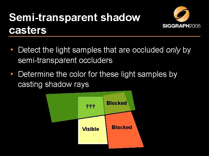
Semi-transparent shadow casters • Detect the light samples that are occluded only by semi-transparent occluders • Determine the color for these light samples by casting shadow rays ? ? ? Visible Blocked