SOFC Interconnect Sealing 2014 06 11 Introduction Interconnect


 Advantage ü High electric conductivity ü The melting")
 Conductivity Fig 4. Conductivity of calcium-doped and")
 Thermal expansion Table 2. CTE of La")


 Metallic Interconnect 의")

 high oxidation rate 2) occurrence of buckling and spallation of")

")
 coating Fig 13. ASR change with time of uncoated and cobalt-coated")
2 formation")


- Slides: 24
SOFC Interconnect & Sealing 2014. 06. 11 권두영
Introduction Interconnect ? Definition - An interconnect is used to physically separate yet electrically connect the anode and cathode of adjacent cells. Fig 1. Planar design for a solid oxide fuel cell (exploded view) 2
Introduction Fig 2. Tubular design for a solid oxide fuel cell 3
Demand characteristics of the ceramic interconnect • • Chemical Stability High Electronic Conductivity Low ionic conductivity Improve Sintering Behavior Thermal Expansion Match Dimensional Stability Chemical Compatibility with other Components Ref. F. 1)Tietz et al. Solid State Ionics 152– 153 (2002) 373– 381, 2)Navadol Laosiripojana et al. ENGINEERING JOURNAL : VOLUME 13 ISSUE 1 ISSN 0125 -8281, 3)N. M SAMMES et al. JOURNAL OF MATERIALS SCIENCE 29 (1994) 4319 -4324 4
lanthanum chromite (La. Cr. O 3) Advantage ü High electric conductivity ü The melting point of La. Cr. O 3 is 2783± 20 K, and the material could remain stable at both the cathode and anode environment. ü Average coefficient of thermal expansion (CTE) of La. Cr. O 3 is 9. 5× 10− 6 K− 1, which is quite close to CTE of YSZ (10. 5× 10− 6 K− 1). Fig 3. Coefficient of thermal expansion (CTE) of interconnect materials 5
La. Cr. O 3 -based material (1) Conductivity Fig 4. Conductivity of calcium-doped and Strontiumdoped lanthanum chromite in air at 1273 K Radius Ca 2+ 0. 134 nm La 3+ 0. 136 nm Sr 2+ 0. 144 nm Table 1. Radius of Ca, La, Sr ions Ref. J. W. Fergus, Solid State Ionic 171 (2004) 1 -15 Fig 5. Conductivity of lanthanum chromite doped cobalt, magnesium, manganese or nickel in air at 1273 K 6
La. Cr. O 3 -based material (2) Thermal expansion Table 2. CTE of La 1 -x. Srx-based materials and 8 YSZ with oxygen or hydrogen atmosphere Fig 6. Coefficient of thermal expansion (CTE) of calcium-or strontium-doped lanthanum chromite. Ref. 1)J. W. Fergus, Solid State Ionic 171 (2004) 1 -15, 2) M. Mori, J. Electrochem. 7 Soc. , 149 (7) (2002), pp. A 797–A 803
La. Cr. O 3 -based material Problem ü Conductivity decreases with decreasing oxygen partial pressure. ü Difficult to sinter to a high relative density. ü ‘La’ is rare-earth element, is expensive. Table 3. Material prices used for each level of manufacturing 8
Demand characteristics of the metallic interconnect • • • Chemical Stability High Electronic Conductivity Thermal Expansion Match Thermal conductivity Imperviousness Low cost Table 3. Characteristics of metallic interconnectors for SOFC 9 Ref. J. W. Wu et al. : J. Mater. Sci. Technol. , 2010, 26(4), 293 -305
Metallic Interconnect 물성 중 성능 및 신뢰성 결정하는 주요 인자 1) Metallic Interconnect 의 면비저항 (ASR, Area specific resistance) 2) Interconnect 소재 내에 포함된 크롬성분의 휘발 ASR, Area specific resistance Metallic Interconnect 의 ASR = [소지금속의 면비저항] + [표면산화물의 면비저항] = [�M x ℓM] + [�ox x ℓox] = [�ox x ℓox] 10
Materials of Metallic Interconnect Fig 7. Schematic of alloy design for SOFC applications Table 4. Comparison of key properties of different alloy groups for SOFC applications Ref. J. W. Wu et al. : J. Mater. Sci. Technol. , 2010, 26(4), 293 -305 11
페라이트계 스텐리스강의 문제점. 1) high oxidation rate 2) occurrence of buckling and spallation of the oxide scale when subjected to thermal cycling 3) volatilization of high valence Cr-species in the form of Cr. O 3, or Cr(OH)2 O 2 12
Oxidation rate Fig 8. Weight gain as a function of oxidation time for the Fe-16 Cr alloy at 650℃ in air Fig 9. Weight gain as a function of oxidation time for the Fe-16 Cr allo at 750℃ in air Ref. Pu Jian et al. : Journal of Power Sources 158 (2006) 354– 360 Fig 10. Weight gain as a function of oxidation time for the Fe-16 Cr alloy at 850℃ in air 13
Spallation of the oxide scale Fig 11. Photos of scale on ends of (a) uncoated and (b) cobalt-coated UNS 430 stainless steel rods after 1900 h oxidation in air at 800℃ Fig 12. SEM cross-section micrograph of (a) uncoated and (b) cobalt-coated UNS 430 stainless steel rods after 1900 h oxidation in air at 800℃ Ref. 1)J. W. Wu et al. : J. Mater. Sci. Technol. , 2010, 26(4), 293 -305, X. Deng et al. : 14 Journal of Power Sources 160 (2006) 1225– 1229
Reactive element oxied(REO) coating Fig 13. ASR change with time of uncoated and cobalt-coated UNS 430 stainless steel. Ref. 1)J. W. Wu et al. : J. Mater. Sci. Technol. , 2010, 26(4), 293305, Xiaohua Deng et al. : Journal of Power Sources 160 (2006) 1225– 1229 Fig 14. ASR changes for uncoated and cobalt-coated UNS 430 stainless steel at 800 ◦C in air 15
volatilization of high valence Cr-species Fig 14. Schematic diagram of Cr. O 2(OH)2 formation and formation of Cr 2 O 3 at the cathode and electrolyte Interface. Ref. J. W. Wu et al. : J. Mater. Sci. Technol. , 2010, 26(4), 293 -305 16
Perovskite coatings ü ABO 2 구조 ü 고온의 산화분위기에서 P-type 전기전도성 ü La 1 -x. Srx. Mn. O 3 , La 1 -x. Srx. Co 1 -y. Fey. O 3 –높은 전도도(200 S/m, 350 S/m) Fig 15. ASR changes with ageing time at 800 °C + 1 h at 930 °C for Crofer 22 APU, uncoated and coated with LCC, LSC, and LSM. Fig 16. Plasma Jet method for Perovskite coatings. Ref. 1)J. W. Wu et al. : J. Mater. Sci. Technol. , 2010, 26(4), 293 -305, 2) Wei-Ja 17 Shong, Materials Chemistry and Physics 127 (2011) 45– 50
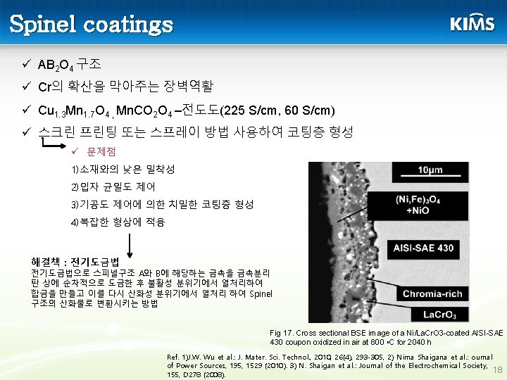
MAl. Cr. YO coating MAl. Cr. Y used as high-temperature oxidation resistant coatings for gas turbine and jet engine blades working at temperatures above 1000℃. • It has been shown that if the coating is thin (<5 m) and Mn and/or Co is used as a part of the coating composition, a relatively low ASR (0. 02– 0. 03 cm 2) can be achieved. • The low ASR has been attributed to incorporation of Mn (from the coating and/or the substrate) into the oxide and the formation of spinel phases with Al, Cr, Co and Mn. These coating are effective in reducing Cr release from the surface. • Table 5. Comparison of different coating materials in terms of capability of improving electronic conductivity, Cr migration inhibition and oxidation rate reduction as well as simplicity of the coating process. Fig 18. ASR measurements for LAFAD coated and uncoated FSS 430 up to 1000 h in 800 ℃ air 19 Ref. 1)Nima Shaigana et al. : ournal of Power Sources, 195, 1529 (2010). 2) P. Gannon, International Journal of Hydrogen Energy 33 ( 2008) 3991– 4000.
SOFC Sealant SOFC Seal functions SOFC seals : ü Prevent mixing of fuel and oxidant within a cell stack ü Prevent leaking of fuel and oxidant from stack ü Electrically isolate cells in stack ü May provide mechanical bonding of cell component Types of seals for SOFC Rigid seals ü Glass and glassceramic sealants ü Brazes Compressive seals ü Metallic compressive seals ü Mica-based compressive seals Ref. Dilshat U et al. : Journal of Power Sources 242 (2013) 486 -502 20
Glass and Glass-ceramic seals : Status Ø Standard aproach to sealing planar stacks • Inexpensive, easy to fabricate (tape casting, slurry dispensing) • Properties can be tailored (CTE, Tg) • Glass-ceramic avoid viscous flow during operation and uncontrolled, progressive crystallization during operation Fig 19. A schematic of the type of viscosity and degree of crystallization behavior Ref. K. D. Meinhardt, Journal of Power Sources 182 (2008) 188– 196 21
SOFC Sealant Ba. O–B 2 O 3–Si. O 2 system with fixed B 2 O 3/Si. O 2 ratio Table 6. Composition of the investigated glasses in molar percent Fig 21. Images of investigated glasses on AISI 430 alloy with relation to temperature Fig 20. Percent of linear change versus temperature for glassceramics, YSZ and AISI 430 alloy Ref. L. Rezazadeh et al. : Ionics (2014) 20: 55– 64 22
Reference ü Junwei Wu. Recent Development of SOFC Metallic Interconnect, J. Mater. Sci. Technol. , 2010, 26(4), 293 -305. ü Harumi Yokokawa. Recent Developments in Solid Oxide Fuel Cell Materials, Fuel cells 2001, 1, No. 2 ü Nima Shaigan. A review of recent progress in coatings, surface modifications and alloy developments for solid oxide fuel cell ferritic stainless steel interconnects, Journal of Power Sources 195 (2010) 1529– 1542 ü Jeffrey W. Fergus. Lanthanum chromite-based materials for solid oxide fuel cell interconnects, Solid State Ionics 171 (2004) 1 – 15 ü Xiaohua Deng. Cobalt plating of high temperature stainless steel interconnects, Journal of Power Sources 160 (2006) 1225– 1229 ü Dilshat U. Aluminosilicate-based sealants for SOFCs and other electrochemical Applications, Journal of Power Sources 242 (2013) 486 -502 ü L. Rezazadeh. Structure, phase formation, and wetting behavior of Ba. O–Si. O 2 –B 2 O 3 based glass–ceramics as sealants for solid oxide fuel cells, Ionics (2014) 20: 55– 64 23
Thank you