
SNPP Visible Infrared Imaging Radiometer Suite VIIRS Lunar
S-NPP Visible Infrared Imaging Radiometer Suite (VIIRS) Lunar Calibration using GSICS Implementation of the ROLO model (GIRO) for Reflective Solar Bands Taeyoung (Jason) Choi, Xi Shao, Changyong Cao, Fuzhong Weng NOAA/NESDIS/STAR VIIRS Team.
Outline • Introduction – – Descriptions of S-NPP VIIRS About Moon Acquisitions Scheduled/Free Moon Collections Input Data Sets • VIIRS Observed Irradiance • Results – Effects of the Modulated RSR – GIRO Irradiance vs. Observed Irradiance • Summary • Future Plan 2
Introduction • Descriptions of S-NPP VIIRS – – – – A whiskbroom scanning radiometer Sun synchronous orbit Field of view of 112. 56⁰ Nominal altitude of 829 km A large scan coverage of 3060 km Equator crossing local time of approximately 13: 30 pm 22 spectral bands • 16 moderate resolution bands (M bands) • 5 imaging resolution bands (I bands) • 1 panchromatic day and night band (DNB band) 3
![Introduction • Description of S-NPP VIIRS Band Center wavelengt h [um] Spatial reso. at](http://slidetodoc.com/presentation_image_h/c11bab5bc1c037e550c95d7785c463d6/image-4.jpg "Introduction • Description of S-NPP VIIRS Band Center wavelengt h [um] Spatial reso. at")
Introduction • Description of S-NPP VIIRS Band Center wavelengt h [um] Spatial reso. at nadir [km] Band Center wavelengt h [um] Spatial reso. at nadir [m] Gain M 1 0. 412 750 High/Low M 12 3. 70 750 Single M 2 0. 445 750 High/Low M 13 4. 05 750 High/Low M 3 0. 488 750 High/Low M 14 8. 55 750 Single M 4 0. 555 750 High/Low M 15 10. 76 750 Single M 5 0. 672 750 High/Low M 16 12. 01 750 Single M 6 0. 746 750 Single I 1 0. 640 375 Single M 7 0. 865 750 High/Low I 2 0. 865 375 Single M 8 1. 24 750 Single I 3 1. 61 375 Single M 9 1. 38 750 Single I 4 3. 74 375 Single M 10 1. 61 750 Single I 5 11. 45 375 Single M 11 2. 25 750 Single DNB 0. 7 750 H/M/L† *The shaded area indicates thermal emissive bands. 4
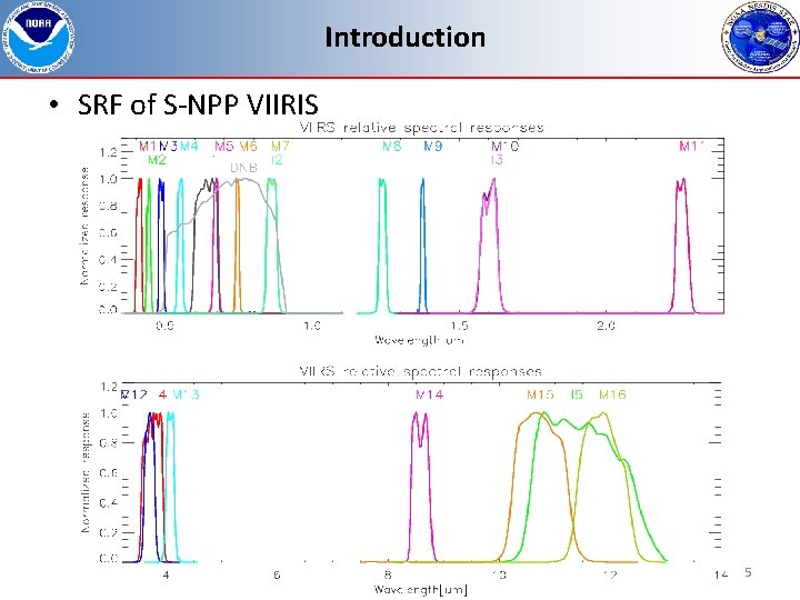
Introduction • SRF of S-NPP VIIRIS 5
Introduction • About Moon Acquisitions – Scheduled Moon Collections • Moon observation made through the Space View (SV). • Sector rotation is applied to place moon in the nadir Earth View (EV) frame. • During the sector rotation, the VIIRS observations are set to be fixed High Gain (HG) mode. • Spacecraft roll maneuvers are required. – Free Moon Collections • Sometimes, moon appears in the SV. • Free moon collections have BBR problems. – On-Board Calibration (OBC) files are not compensated compared to normal EV Science Data Records (SDR) products. – Focused on the scheduled moon collection in this study. 6

Introduction Focal Plane Interface Electronics From VIIRS Radiometric ATBD. 7
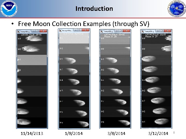
Introduction • Free Moon Collection Examples (through SV) 11/14/2013 1/8/2014 3/12/2014 8
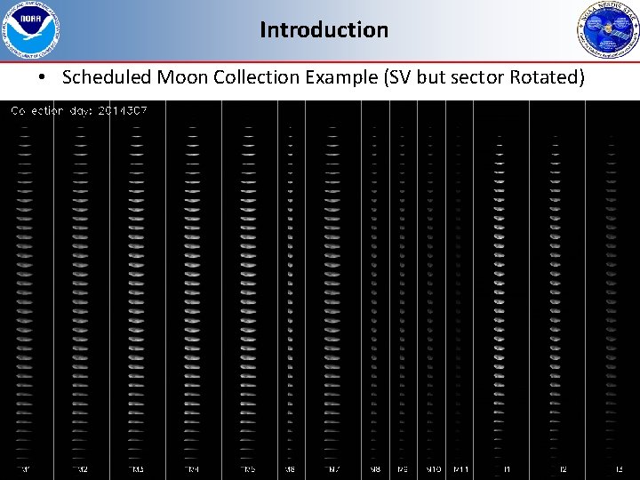
Introduction • Scheduled Moon Collection Example (SV but sector Rotated) 9
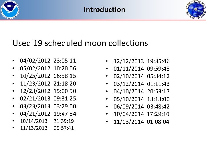
Introduction Used 19 scheduled moon collections • • 04/02/2012 05/02/2012 10/25/2012 11/23/2012 12/23/2012 02/21/2013 03/23/2013 04/21/2012 • 10/14/2013 • 11/13/2013 23: 05: 11 10: 20: 06 06: 58: 15 21: 18: 20 15: 00: 50 09: 31: 25 03: 29: 00 19: 47: 54 21: 39: 19 06: 57: 41 • • • 12/12/2013 01/11/2014 02/10/2014 03/12/2014 04/10/2014 05/10/2014 06/09/2014 10/04/2014 11/03/2014 19: 35: 46 09: 59: 45 05: 34: 12 01: 11: 43 20: 53: 17 13: 00 03: 48: 42 17: 29: 10 01: 08: 04
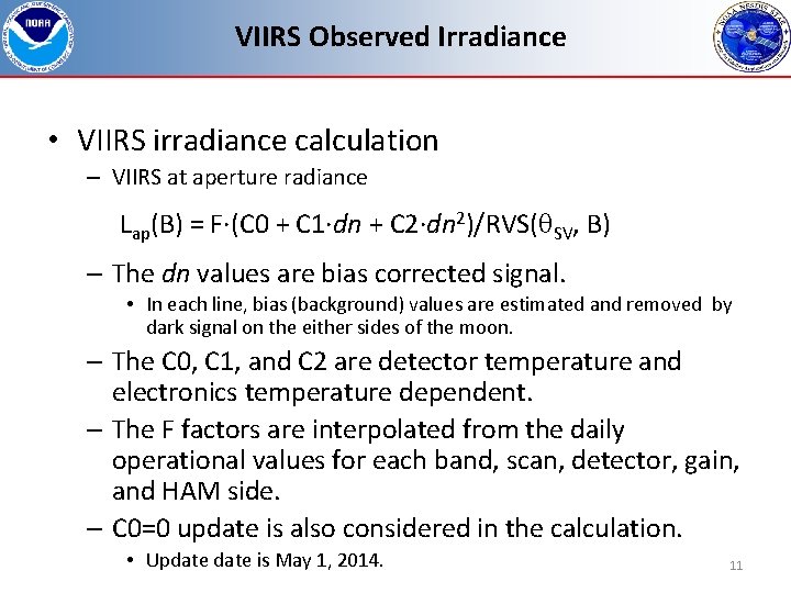
VIIRS Observed Irradiance • VIIRS irradiance calculation – VIIRS at aperture radiance Lap(B) = F·(C 0 + C 1·dn + C 2·dn 2)/RVS( SV, B) – The dn values are bias corrected signal. • In each line, bias (background) values are estimated and removed by dark signal on the either sides of the moon. – The C 0, C 1, and C 2 are detector temperature and electronics temperature dependent. – The F factors are interpolated from the daily operational values for each band, scan, detector, gain, and HAM side. – C 0=0 update is also considered in the calculation. • Update is May 1, 2014. 11
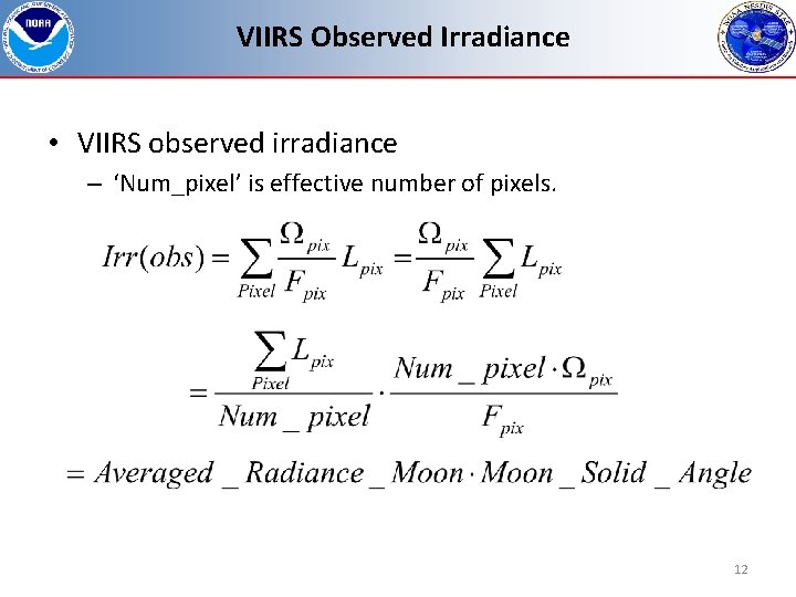
VIIRS Observed Irradiance • VIIRS observed irradiance – ‘Num_pixel’ is effective number of pixels. 12
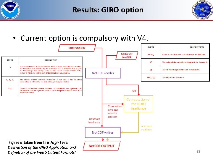
Results: GIRO option • Current option is compulsory with V 4. Figure is taken from the ‘High Level Description of the GIRO Application and Definition of the Input/Output Formats’ 13
Results: Effects of the Modulated RSR • SNPP VIIRS Modulated RSR (or SRF) Released due to tungsten contamination in the Rotating Telescope Assembly (RTA). – The modulated RSR has been applied beginning of April 5, 2013. • For previous dates of the RSR update, Northrop Grumman (NG) provided official band-averaged RSR functions are used. • The GIRO output differences are less than 0. 14% between the two RSR functions. – Only band M 1 shows 0. 13% level whereas all other bands are less than 0. 07% or less. • NG RSR functions are used before April 5, 2013. • Modulated RSR function are used after the update. 14
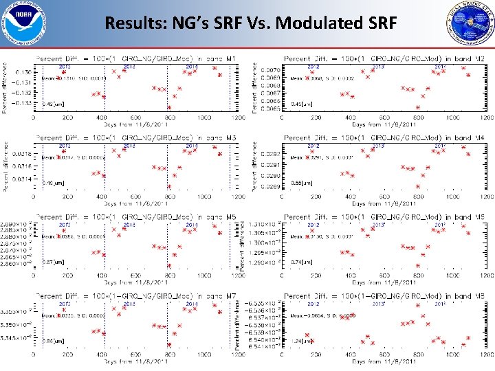
Results: NG’s SRF Vs. Modulated SRF 15
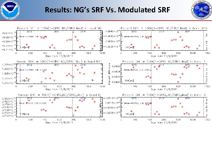
Results: NG’s SRF Vs. Modulated SRF 16
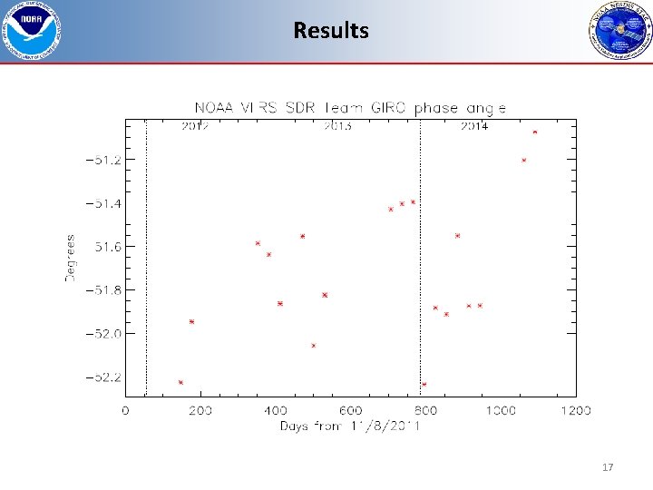
Results 17
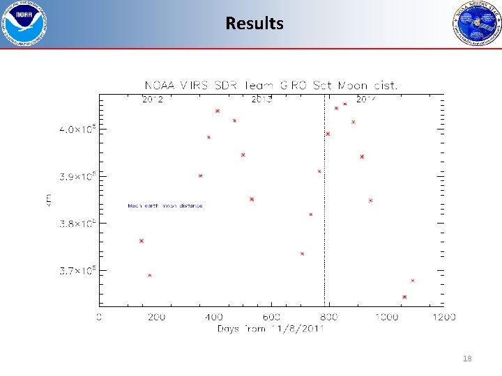
Results 18
Results 19
Results 20
Results 21
Results 22
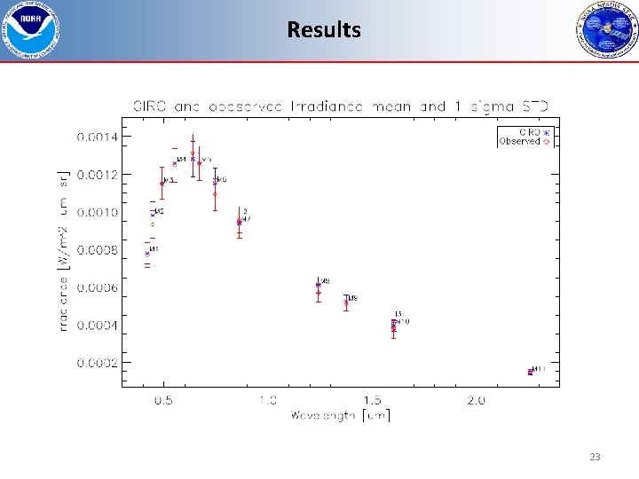
Results 23
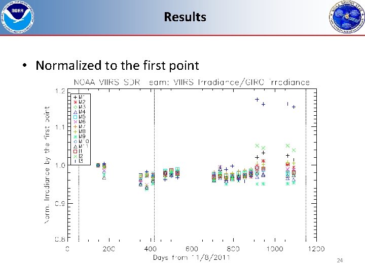
Results • Normalized to the first point 24
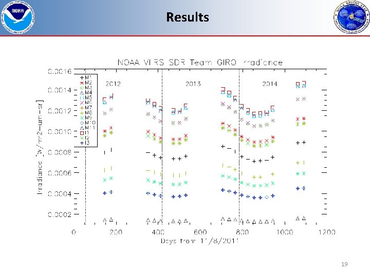
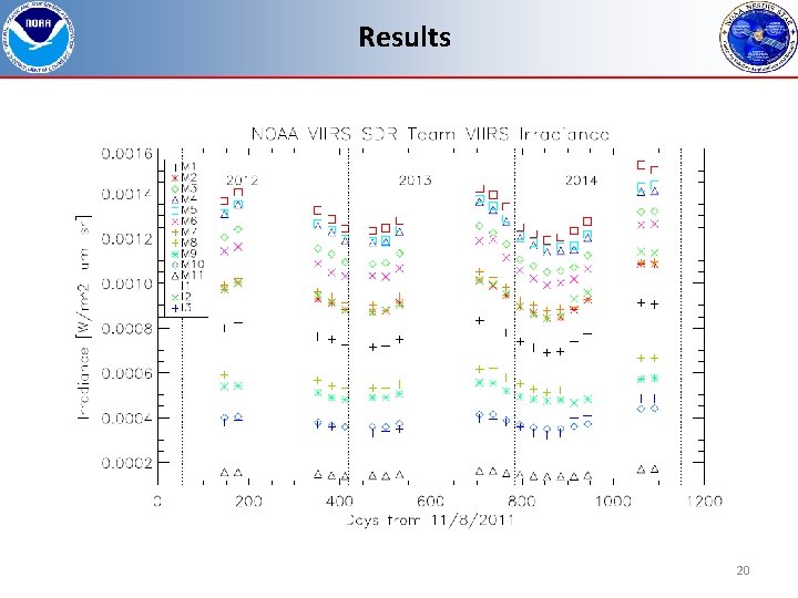
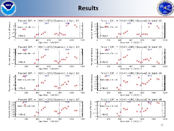
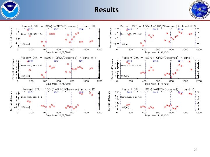
Summary • The GIRO version 4 was successfully implemented and produced lunar irradiance values for SNPP VIIRS scheduled moon collections. • Corresponding VIIRS irradiance values are calculated using effective pixel averaging method. • In irradiance scale, specific bands M 2, M 6, M 8, M 11 and I 3 shows static differences larger than 5%. – M 11 has low SNR and I 3 has C 0=0 update issues. • Other bands show reasonable agreements between GIRO and observed irradiances approximately within 3%. 25
Future Plan • Based on GIRO irradiance results, the Lunar calibration coefficient (F-factor) will be compared to the operational F-factors. – Not using the relative comparisons. Imoon(B, M, G) = Mean_radiance(B, M, G, D) · = pixel {(C 0 + C 1·dn + C 2·dn 2)/RVS( SV, B)}/N_Pixel · • Work on free moon collections. 26
Backup Slides
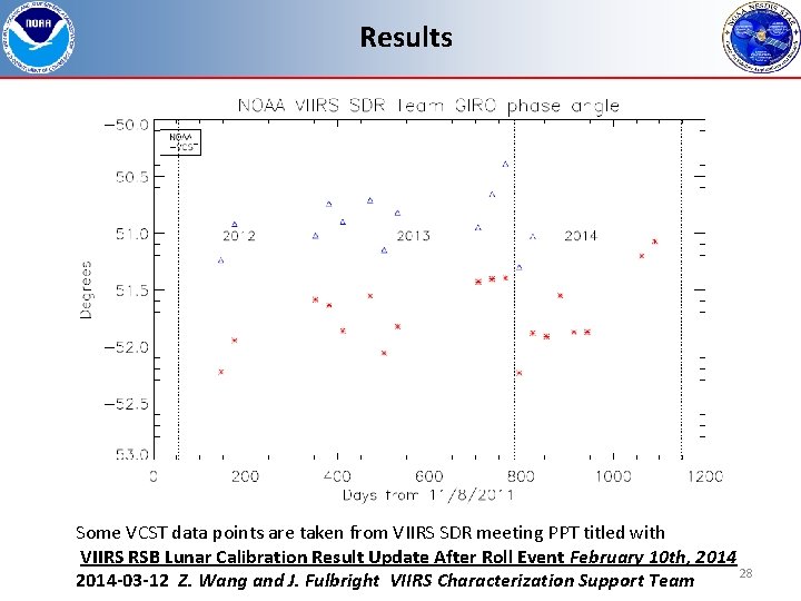
Results Some VCST data points are taken from VIIRS SDR meeting PPT titled with VIIRS RSB Lunar Calibration Result Update After Roll Event February 10 th, 2014 28 2014 -03 -12 Z. Wang and J. Fulbright VIIRS Characterization Support Team
- Slides: 28