Sludge Management In all biological waste treatment processes


Sludge Management In all biological waste treatment processes some surplus sludge is produced. The objective of residual management is: 1. Reduction of water content. 2. Stabilization of sludge solids. 3. Reduction in sludge solids volume.

In facultative type aerated lagoons and algal waste stabilization ponds, the surplus sludge settles out in the unit itself and is removed only once in a few years after emptying the unit, exposing the wet sludge to natural drying, and carting away the dried sludge for agricultural use or land filling. In extended aeration process where aerobic digestion of surplus sludge is done, the sludge can be taken directly for dewatering and disposal. In case of activated sludge and trickling filter plants, the sludge is taken (along with the primary sludge) to a sludge digester for further demineralization and thereafter it is dewatered.

Sludge Dewatering Methods 1. Natural: sludge drying beds, sludge lagoons 2. Mechanical: sludge thickeners, centrifuges, vacuum filters, filter press 3. Physical: heat drying, incineration


Disposal of Sludge Final disposal of sludge is to land sometimes to the sea, in one of the following ways: 1. Agricultural use of dried or wet sludge. 2. Use of dried sludge as landfill in absence of agricultural demand. 3. Spreading wet sludge on eroded or waste land, contouring the field, so as to gradually build up a top soil of agricultural value. 4. Disposing off wet sludge along with solid wastes for (i) composting, or (ii) sanitary landfill. 5. Transporting and dumping into the sea.

Sludge Characteristics For the rational design of sludge drying systems, it is essential to know a few characteristics of sludge, such as moisture content as affected by the nature and extent of organic and other matter contained in them, their specific gravity, weight and volume relationships, their dewatering characteristics, etc. The specific gravity of sludge is very close to that of water itself, 1. 01 for biological sludge and 1. 02 from alum sludge.


Stepwise reduction in moisture content in dewatering extended aeration sludge Sludge source Moisture content Weight, g/person-day % by weight Solids Water Total Initial moisture content 99 30 2970 3000 After thickening 96 30 720 750 After other mechanical process 90 30 270 300 After natural or physical drying 60 30 45 75

It is evident that the bulk of the water is removed in the thickener. Thereafter, the bulk of the remaining moisture is removed in free drainage. Evaporation removes the least but, in fact, takes the longest time. The final "dried" sludge still has considerable moisture in it, but the sludge is now "handleable".

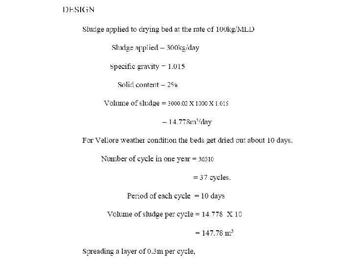
Sand Beds for Sludge Drying Sand beds are generally constructed as shown in the typical cross-sectional view.

Sludge is generally spread over the sand which is supported on a gravel bed, through which is laid an open-joint earthen pipe 15 cm in diameter spaced about 3 m apart and sloping at a gradient of 1 in 150 towards the filtrate sump. The drying beds are often subdivided into smaller units, each bed 5 -8 m wide and 15 -50 m long. The drying time averages about 1 -2 weeks in warmer climates, and 3 -6 or even more in unfavorable ones.

Sludge Digestion Sludge digestion involves the treatment of highly concentrated organic wastes in the absence of oxygen by anaerobic bacteria. The anaerobic treatment of organic wastes resulting in the production of carbon dioxide and methane, involves two distinct stages. In the first stage, referred to as "acid fermentation", complex waste components, including fats, proteins, and polysaccharides are first hydrolyzed by a heterogeneous group of facultative and anaerobic bacteria. These bacteria then subject the products of hydrolysis to fermentations, b-oxidations, and other metabolic processes leading to the formation of simple organic compounds, mainly short-chain (volatile) acids and alcohols. However in the second stage, referred to as "methane fermentation", the end products of the first stage are converted to gases (mainly methane and carbon dioxide) by several different species of strictly anaerobic bacteria.

The bacteria responsible for acid fermentation are relatively tolerant to changes in p. H and temperature and have a much higher rate of growth than the bacteria responsible for methane fermentation. If the p. H drops below 6. 0, methane formation essentially ceases, and more acid accumulates, thus bringing the digestion process to a standstill. As a result, methane fermentation is generally assumed to be the rate limiting step in anaerobic wastewater treatment. The methane bacteria are highly active in mesophilic (27 -43°C) with digestion period of four weeks and thermophilic range (35 -40°C) with digestion period of 15 -18 days. But thermophilic range is not practised because of odour and operational difficulties.

Digestion Tanks or Digesters A sludge digestion tank is a RCC or steel tank of cylindrical shape with hopper bottom and is covered with fixed or floating type of roofs.

Types of Anaerobic Digesters The anaerobic digesters are of two types: standard rate and high rate. In the standard rate digestion process, the digester contents are usually unheated and unmixed. The digestion period may vary from 30 to 60 d. In a high rate digestion process, the digester contents are heated and completely mixed. The required detention period is 10 to 20 d.
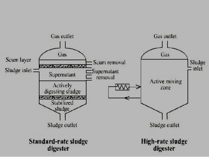

Often a combination of standard and high rate digestion is achieved in two-stage digestion. The second stage digester mainly separates the digested solids from the supernatant liquor, although additional digestion and gas recovery may also be achieved.

Gas Collection The amount of sludge gas produced varies from 0. 014 to 0. 028 m 3 per capita. The sludge gas is normally composed of 65% methane and 30% carbondioxide and remaining 5% of nitrogen and other inert gases, with a calorific value of 5400 to 5850 kcal/m 3.

Settling Solid liquid separation process in which a suspension is separated into two phases 1. Clarified supernatant leaving the top of the sedimentation tank (overflow). 2. Concentrated sludge leaving the bottom of the sedimentation tank (underflow). Purpose of Settling 1. To remove coarse dispersed phase. 2. To remove coagulated and flocculated impurities. 3. To remove precipitated impurities after chemical treatment. 4. To settle the sludge (biomass) after activated sludge process / tricking filters.

Principle of Settling 1. Suspended solids present in water having specific gravity greater than that of water tend to settle down by gravity as soon as the turbulence is retarded by offering storage. 2. Basin in which the flow is retarded is called settling tank. 3. Theoretical average time for which the water is detained in the settling tank is called the detention period.

Types of Settling Type I: Discrete particle settling - Particles settle individually without interaction with neighboring particles. Type II: Flocculent Particles – Flocculation causes the particles to increase in mass and settle at a faster rate. Type III: Hindered or Zone settling –The mass of particles tends to settle as a unit with individual particles remaining in fixed positions with respect to each other. Type IV: Compression – The concentration of particles is so high that sedimentation can only occur through compaction of the structure.

Types of Settling

Types of Settling Tanks 1. Sedimentation tanks may function either intermittently or continuously. 2. The intermittent tanks also called quiescent type tanks are those which store water for a certain period and keep it in complete rest. 3. In a continuous flow type tank, the flow velocity is only reduced and the water is not brought to complete rest as is done in an intermittent type. 4. Settling basins may be either long rectangular or circular in plan. 5. Long narrow rectangular tanks with horizontal flow are generally preferred to the circular tanks with radial or spiral flow.

Rectangular sedimentation Tank

Rectangular Sedimentation Tank

Circular Sedimentation Tank

Long Rectangular Settling Basin Long rectangular basins are hydraulically more stable, and flow control for large volumes is easier with this configuration. A typical long rectangular tank have length ranging from 2 to 4 times their width. The bottom is slightly sloped to facilitate sludge scraping. A slow moving mechanical sludge scraper continuously pulls the settled material into a sludge hopper from where it is pumped out periodically.

A long rectangular settling tank can be divided into four different functional zones: Inlet zone: Region in which the flow is uniformly distributed over the cross section such that the flow through settling zone follows horizontal path. Settling zone: Settling occurs under quiescent conditions. Outlet zone: Clarified effluent is collected and discharge through outlet weir. Sludge zone: For collection of sludge below settling zone.
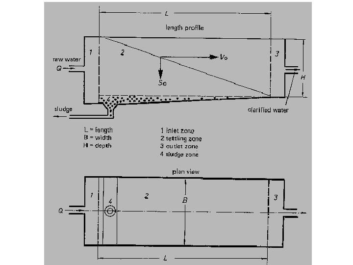

Design Details 1. Detention period: for plain sedimentation: 2 to 4 h, and for coagulated sedimentation: 4 to 6 h. 2. Velocity of flow: Not greater than 30 cm/min (horizontal flow). 3. Tank dimensions: L: B = 3 to 5: 1. Generally L= 30 m (common) maximum 100 m. Breadth= 6 m to 10 m. Circular: Diameter not greater than 60 m. generally 20 to 40 m. 4. Depth: 2. 5 to 5. 0 m (3 m). 5. Surface Overflow Rate: For plain sedimentation 24000 to 60000 L/d/m 2 tank area; for thoroughly flocculated water 14400 to 24000 L/d/m 2 tank area. 6. Slopes: Rectangular 1% towards inlet and circular 8%.

Sedimentation Tank Design Problem: Design a rectangular sedimentation tank to treat 2. 4 million liters of raw water per day. The detention period may be assumed to be 3 hours. Solution: Raw water flow per day is 2. 4 x 10⁶ l. Detention period is 3 h. Volume of tank = Flow x Detention period = 2. 4 x 103 x 3/24 = 300 m 3 Assume depth of tank = 3. 0 m. Surface area = 300/3 = 100 m 2 L/B = 3 (assumed). L = 3 B. 3 B 2 = 100 m 2 i. e. B = 5. 8 m L = 3 B = 5. 8 X 3 = 17. 4 m Hence surface loading (Overflow rate) = 2. 4 x 106 = 24, 000 l/d/m 2 < 40, 000 l/d/m 2 (OK) 100

Batch Settler • Occur in vessel or ponds Tap Points Solid Removal • Are simply filled and then allowed to stand until the desired degree of separation is achieved • Open or closed operation • More tap points can be implemented

Continuous Settler • To treat a stream for clarification or slurry to be thickened Feed Tap Points • Feed and flow from thickener (or tap points) are continuous • Solids removal – continuous or intermittent • Horizontal, vertical, or inclined Solid Removal

Horizontal Separators • Used for clarification operations • Feed enters on one end and the clarified liquid overflows at the other • Solid removal is done intermittently at the bottom of the vessel

Vertical Thickeners

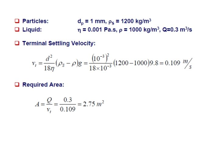
Sizing of Gravity Settling Tank:

Sizing of Gravity Settling Tank:

Find the area of the gravity settling required the optimal condition

Sizing of industrial thickeners:

Sizing of industrial thickeners:

Activated Sludge Process The most common suspended growth process used for municipal wastewater treatment is the activated sludge process as shown in figure:
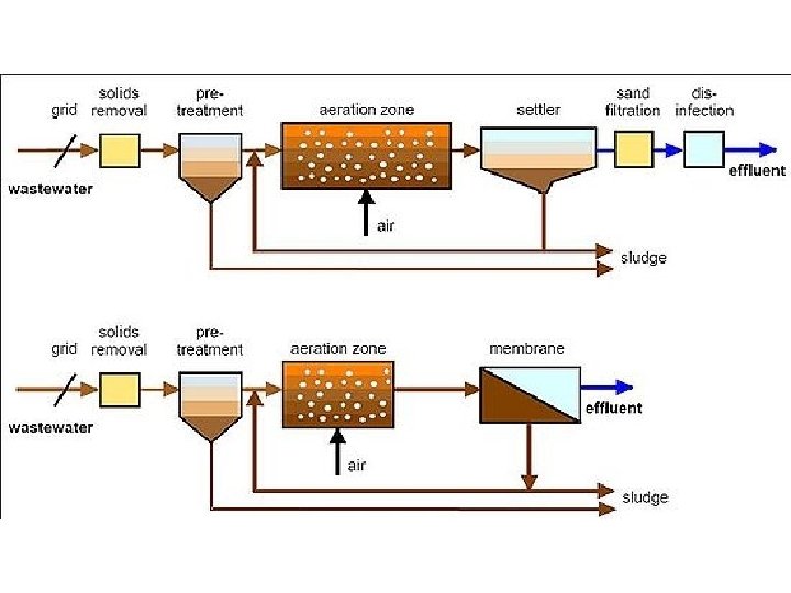

Activated sludge plant involves: 1. wastewater aeration in the presence of a microbial suspension, 2. solid-liquid separation following aeration, 3. discharge of clarified effluent, 4. wasting of excess biomass, and 5. return of remaining biomass to the aeration tank.

In activated sludge process wastewater containing organic matter is aerated in an aeration basin in which micro-organisms metabolize the suspended and soluble organic matter. Part of organic matter is synthesized into new cells and part is oxidized to CO 2 and water to derive energy. In activated sludge systems the new cells formed in the reaction are removed from the liquid stream in the form of a flocculent sludge in settling tanks. A part of this settled biomass, described as activated sludge is returned to the aeration tank and the remaining forms waste or excess sludge.

Activated Sludge Process Variables The main variables of activated sludge process are 1. The mixing regime, 2. Loading rate, and 3. The flow scheme.

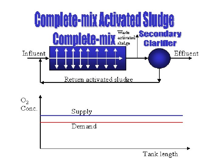
Mixing Regime Generally two types of mixing regimes are of major interest in activated sludge process: plug flow and complete mixing. 1. In the first one, the regime is characterized by orderly flow of mixed liquor through the aeration tank with no element of mixed liquor overtaking or mixing with any other element. There may be lateral mixing of mixed liquor but there must be no mixing along the path of flow. 2. In complete mixing, the contents of aeration tank are well stirred and uniform throughout. Thus, at steady state, the effluent from the aeration tank has the same composition as the aeration tank contents.

Plug flow

Complete flow mixing
 oxygen transfer")
The type of mixing regime is very important as it affects (1) oxygen transfer requirements in the aeration tank, (2) susceptibility of biomass to shock loads, (3) local environmental conditions in the aeration tank, and (4) the kinetics governing the treatment process

Loading Rate A loading parameter that has been developed over the years is the hydraulic retention time (HRT), q, d q= V Q V= volume of aeration tank, m 3, and Q= sewage inflow, m 3/d Another empirical loading parameter is volumetric organic loading which is defined as the BOD applied per unit volume of aeration tank, per day.

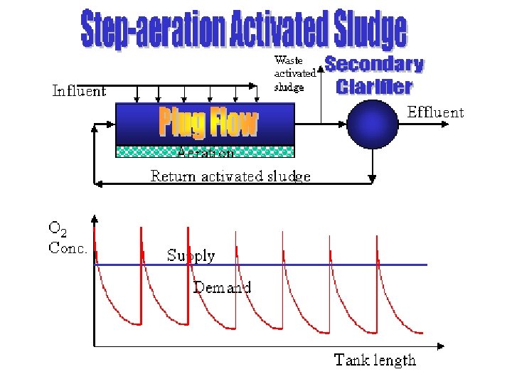
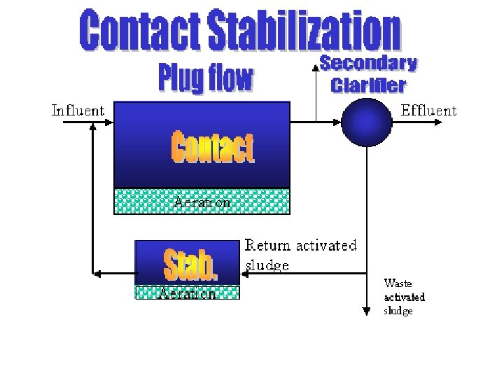
Conventional System and its Modifications The conventional system maintains a plug flow hydraulic regime. Over the years, several modifications to the conventional system have been developed to meet specific treatment objectives. In step aeration settled sewage is introduced at several points along the tank length which produces more uniform oxygen demand throughout. Tapered aeration attempts to supply air to match oxygen demand along the length of the tank. Contact stabilization provides for reaeration of return activated sludge from the final clarifier, which allows a smaller aeration or contact tank.

Completely mixed process aims at instantaneous mixing of the influent waste and return sludge with the entire contents of the aeration tank. Extended aeration process operates at a low organic load producing lesser quantity of well stabilized sludge.

Trickling Filters Trickling filter is an attached growth process i. e. process in which microorganisms responsible for treatment are attached to an inert packing material. Packing material used in attached growth processes include rock, gravel, slag, sand, redwood, and a wide range of plastic and other synthetic materials.

Trickling Filter

Process Description The wastewater in trickling filter is distributed over the top area of a vessel containing non-submerged packing material. Air circulation in the void space, by either natural draft or blowers, provides oxygen for the microorganisms growing as an attached biofilm. During operation, the organic material present in the wastewater is metabolized by the biomass attached to the medium. The biological slime grows in thickness as the organic matter abstracted from the flowing wastewater is synthesized into new cellular material. The thickness of the aerobic layer is limited by the depth of penetration of oxygen into the microbial layer.

The micro-organisms near the medium face enter the endogenous phase as the substrate is metabolized before it can reach the micro-organisms near the medium face as a result of increased thickness of the slime layer and loose their ability to cling to the media surface. The liquid then washes the slime off the medium and a new slime layer starts to grow. This phenomenon of losing the slime layer is called sloughing. The sloughed off film and treated wastewater are collected by an under drainage which also allows circulation of air through filter. The collected liquid is passed to a settling tank used for solid- liquid separation.

Types of Filters Trickling filters are classified as high rate or low rate, based on the organic and hydraulic loading applied to the unit. Sl. No. Design Feature Low Rate Filter High Rate Filter 1. Hydraulic loading, m 3/m 2. d 1 -4 10 - 40 2. Organic loading, kg BOD / m 3. d 0. 08 - 0. 32 - 1. 0 3. Depth, m. 1. 8 - 3. 0 0. 9 - 2. 5 0 0. 5 - 3. 0 (domestic wastewater) up to 8 for strong industrial wastewater. 4. Recirculation ratio

Process Design

Generally trickling filter design is based on empirical relationships to find the required filter volume for a designed degree of wastewater treatment. Types of equations: 1. NRC equations (National Research Council of USA) 2. Rankin's equation 3. Eckenfelder equation 4. Galler and Gotaas equation NRC and Rankin's equations are commonly used. NRC equations give satisfactory values when there is no re-circulation, the seasonal variations in temperature are not large and fluctuations with high organic loading. Rankin's equation is used for high rate filters.

Rankin's equation: This equation also known as Tentative Method of Ten States USA has been successfully used over wide range of temperature. It requires following conditions to be observed for single stage filters: Raw settled domestic sewage BOD applied to filters should not exceed 1. 2 kg BOD 5/day/ m 3 filter volume. Hydraulic load (including recirculation) should not exceed 30 m 3/m 2 filter surface-day. Recirculation ratio (R/Q) should be such that BOD entering filter (including recirculation) is not more than three times the BOD expected in effluent.

This implies that as long as the above conditions are satisfied efficiency is only a function of recirculation and is given by: E= (R/Q) + 1. 5
 process, the media")
The Rotating Biological Contactor Process In the Rotating Biological Contactor (RBC) process, the media is in the form of a drum. The microorganisms grow on this drum. The drum is slowly rotated, periodically submerging the microorganisms in the wastewater, where they are able to remove organic materials from the wastewater food.

Rotating Biological Contactor
- Slides: 77