
SLS Emittance Monitor Natalia Milas Masamitsu Aiba ke
SLS Emittance Monitor Natalia Milas, Masamitsu Aiba, Åke Andersson, Michael Böge, Jonas Breunlin, Martin Rohrer, Angela Saa-Hernandez, Volker Schlott and Andreas Streun October 25 th 2012 LCWS 2012 – CLIC/ILC working group on Damping Rings
Emittance Monitor at SLS Contents • Motivation – EU-Project TIARA WP-6 SVET • Swiss Light Source – 1 pmrad Vertical Emittance • Measurement Principle – p-Polarization Method • New Monitor Design – Advantages and New Features • Critial Issues and Components Natalia Milas, LCWS 12, Arlington, October 25 th,
Emittance Monitor at SLS Test Infrastructure and Accelerator Research Area www. eu-tiara. eu Work Package 6 “SVET” Partially funded by the European Commission under the FP 7 -INFRASTRUCTURES-2010 -1/ INFRA-2010 -2. 2. 11 project TIARA (CNI-PP). Grant agreement no 261905. SVET: SLS Vertical Emittance Tuning investigate ultra-low vertical emittance tuning and control in the regime of strong IBS relevance for damping rings of future linear colliders & for next generation light sources upgrade Swiss Light Source to enable R&D on ultra-low emittances SVET Partners PSI CERN INFN/LNF Max-IV-Lab Natalia Milas, LCWS 12, Arlington, October 25 th, SLS coupling suppression and control CLIC damping ring design Super-B factory design MAX-IV emittance measurement and coupling control
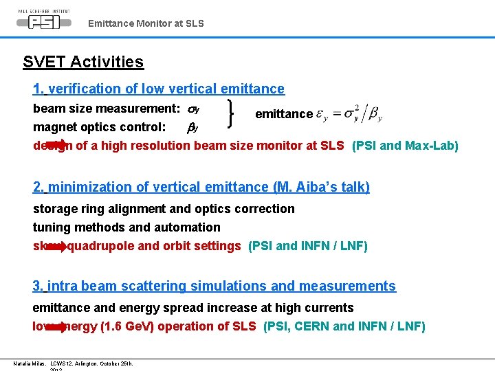
Emittance Monitor at SLS SVET Activities 1. verification of low vertical emittance beam size measurement: sy emittance magnet optics control: by design of a high resolution beam size monitor at SLS (PSI and Max-Lab) 2. minimization of vertical emittance (M. Aiba’s talk) storage ring alignment and optics correction tuning methods and automation skew quadrupole and orbit settings (PSI and INFN / LNF) 3. intra beam scattering simulations and measurements emittance and energy spread increase at high currents low energy (1. 6 Ge. V) operation of SLS (PSI, CERN and INFN / LNF) Natalia Milas, LCWS 12, Arlington, October 25 th,
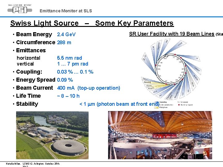
Emittance Monitor at SLS Swiss Light Source – Some Key Parameters SR User Facility with 19 Beam Lines (Stat • Beam Energy 2. 4 Ge. V • Circumference 288 m • Emittances horizontal vertical • Coupling: • Energy Spread • Beam Current • Life Time • Stability 5. 5 nm rad 1 … 7 pm rad 0. 03 % … 0. 1 % 0. 09 % 400 m. A (top-up operation) ~ 8 – 10 h Natalia Milas, LCWS 12, Arlington, October 25 th, < 1 mm (photon beam at front end)
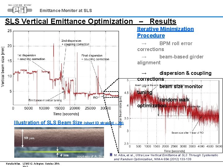
Emittance Monitor at SLS Vertical Emittance Optimization – Results Iterative Minimization Procedure → BPM roll error corrections → beam-based girder alignment → dispersion & coupling corrections → beam size monitor tuning → random walk optimization Illustration of SLS Beam Size (short ID straight – 2 s) courtesy of A. Streun Natalia Milas, LCWS 12, Arlington, October 25 th, M. Aiba, et al. , Ultra Low Vertical Emittance at SLS Through Systematic and Random Optimization, NIM-A 694 (2012) 133 -139
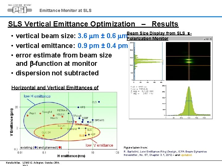
Emittance Monitor at SLS Vertical Emittance Optimization – Results Size Display from SLS • vertical beam size: 3. 6 mm ± 0. 6 mm. Beam Polarization Monitor • vertical emittance: 0. 9 pm ± 0. 4 pm • error estimate from beam size and b-function at monitor • dispersion not subtracted p- Horizontal and Vertical Emittances of Storage Rings existing ( ) and planned ( ) Figure taken from: R. Bartolini, Low Emittance Ring Design, ICFA Beam Dynamics Newsletter, No. 57, Chapter 3. 1, 2012 – and updated. Natalia Milas, LCWS 12, Arlington, October 25 th,
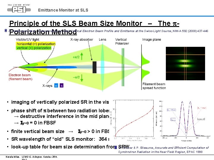
Emittance Monitor at SLS Principle of the SLS Beam Size Monitor – The p Å. Andersson, et al. , Determination of Small Vertical Electron Beam Profile and Emittance at the Swiss Light Source, NIM-A 592 (2008) 437 -446 Polarization Method • imaging of vertically polarized SR in the visible / UV • phase shift of p between two radiation lobes → destructive interference in the mid plane → Iy=0 = 0 in FBSF • finite vertical beam size → Iy=0 > 0 in FBSF • SR wavelength of “old” SLS monitor: 364 nm • look-up table for beam size determination from SRW O. Chubar & P. Elleaume, Accurate and Efficient Computation of Synchrotron Radiation in the Near Field Region, EPAC 1998 Natalia Milas, LCWS 12, Arlington, October 25 th,
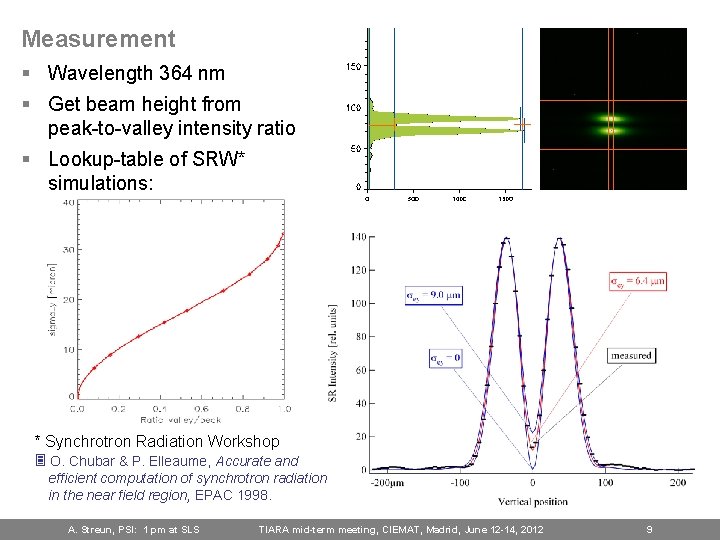
Measurement § Wavelength 364 nm § Get beam height from peak-to-valley intensity ratio § Lookup-table of SRW* simulations: * Synchrotron Radiation Workshop O. Chubar & P. Elleaume, Accurate and efficient computation of synchrotron radiation in the near field region, EPAC 1998. A. Streun, PSI: 1 pm at SLS TIARA mid-term meeting, CIEMAT, Madrid, June 12 -14, 2012 9
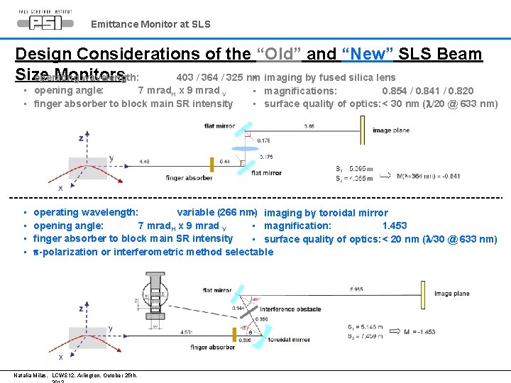
Emittance Monitor at SLS Design Considerations of the “Old” and “New” SLS Beam Size Monitors • operating wavelength: 403 / 364 / 325 nm • imaging by fused silica lens • opening angle: 7 mrad. H x 9 mrad V • finger absorber to block main SR intensity • • • magnifications: 0. 854 / 0. 841 / 0. 820 • surface quality of optics: < 30 nm (l/20 @ 633 nm) operating wavelength: variable (266 nm) • imaging by toroidal mirror opening angle: 7 mrad. H x 9 mrad V • magnification: 1. 453 finger absorber to block main SR intensity • surface quality of optics: < 20 nm (l/30 @ 633 nm) p-polarization or interferometric method selectable Natalia Milas, LCWS 12, Arlington, October 25 th,
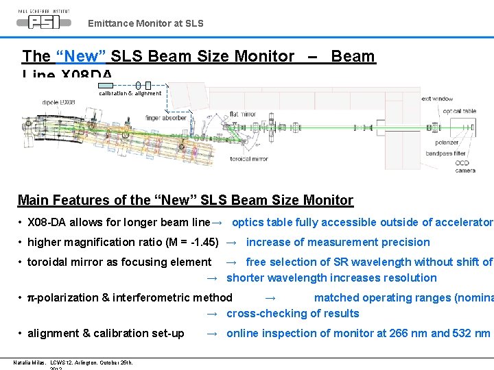
Emittance Monitor at SLS The “New” SLS Beam Size Monitor – Beam Line X 08 DA calibration & alignment Main Features of the “New” SLS Beam Size Monitor • X 08 -DA allows for longer beam line→ optics table fully accessible outside of accelerator • higher magnification ratio (M = -1. 45) → increase of measurement precision • toroidal mirror as focusing element → free selection of SR wavelength without shift of → shorter wavelength increases resolution • p-polarization & interferometric method → matched operating ranges (nomina → cross-checking of results • alignment & calibration set-up Natalia Milas, LCWS 12, Arlington, October 25 th, → online inspection of monitor at 266 nm and 532 nm
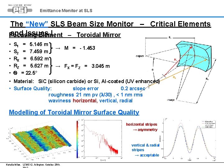
Emittance Monitor at SLS The “New” SLS Beam Size Monitor – Critical Elements and Issues I Focusing Element – Toroidal Mirror • • • S 1 S 2 RX RZ Q = 5. 146 m = 7. 459 m = 6. 592 m = 5. 627 m = 22. 5° → M = - 1. 453 → FX = FZ = 3. 045 m • Material: Si. C (silicon carbide) or Si, Al-coated (UV enhanced) • Surface Quality: slope error 0. 2 arcsec roughness 21 nm pv (l/30) , < 1 nm rms waviness horizontal, vertical, radial Modelling of Toroidal Mirror Surface Quality horizontal stripes → asymmetry vertical & radial stripes → acceptable Natalia Milas, LCWS 12, Arlington, October 25 th,
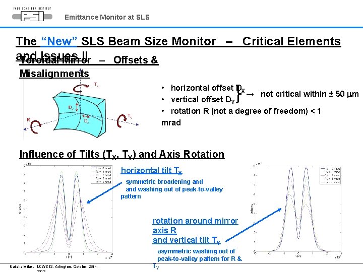
Emittance Monitor at SLS The “New” SLS Beam Size Monitor – Critical Elements and Issues II – Offsets & Toroidal Mirror Misalignments • horizontal offset DX → not critical within ± 50 mm • vertical offset DY • rotation R (not a degree of freedom) < 1 mrad Influence of Tilts (TX, TY) and Axis Rotation horizontal tilt TX symmetric broadening and washing out of peak-to-valley pattern rotation around mirror axis R and vertical tilt TY asymmetric washing out of peak-to-valley pattern for R & Natalia Milas, LCWS 12, Arlington, October 25 th, TY
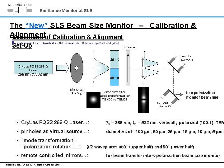
Emittance Monitor at SLS The “New” SLS Beam Size Monitor – Calibration & Alignment Schematic of Calibration & Alignment mode images from: Meyrath et al. , Opt. Express, Vol. 13, Issue 8, pp. 2843 -2851 (2005) Set-Up polarizer remote mirror-1 Df = 0 Cry. Las FQSS 266 -Q Laser 266 nm & 532 nm Df = p pinholes 100 - 5 mm waveplates for mode transformation TEM 00 → TEM 01 to p-polarization monitor beam line remote mirror-2 • Cry. Las FQSS 266 -Q Laser…: l 1 = 266 nm, l 2 = 532 nm, vertically polarized (100: 1), TEM • pinholes as virtual source…: diameters of 100 mm, 50 mm, 25 mm, 10 mm, 5 mm, • “mode transformation” “polarization rotation”…: l/2 waveplates at 0° (upper half) and 90° (lower half) • remote controlled mirrors…: Natalia Milas, LCWS 12, Arlington, October 25 th, for beam transfer into p-polarization beam size monitor
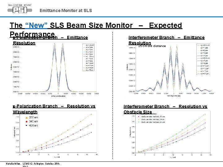
Emittance Monitor at SLS The “New” SLS Beam Size Monitor – Expected Performance p-Polarization Branch – Emittance Interferometer Branch – Emittance Resolution p-Polarization Branch – Resolution vs Wavelength Natalia Milas, LCWS 12, Arlington, October 25 th, Resolution 25 cm slit distance Interferometer Branch – Resolution vs Obstacle Size
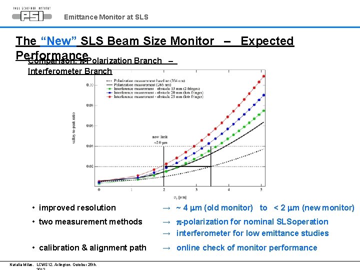
Emittance Monitor at SLS The “New” SLS Beam Size Monitor – Expected Performance Comparison: p-Polarization Branch – Interferometer Branch • improved resolution → ~ 4 mm (old monitor) to < 2 mm (new monitor) • two measurement methods → p-polarization for nominal SLSoperation → interferometer for low emittance studies • calibration & alignment path → online check of monitor performance Natalia Milas, LCWS 12, Arlington, October 25 th,
Emittance Monitor at SLS Summary and Outlook • methods for emittance tuning established at SLS (within TIARA-SVET collaboration) → lowest vertical emittance of 0. 9 ± 0. 4 pmrad • design of “new” high resolution beam size monitor at SLS → application of p-polarization and interferometeric methods → overlapping sensitivity ranges for nominal SLS operation and low emittance studies → mirror optics (toroidal focusing mirror) provides free selection of SR wavelength → sensitivity study using SRW provides specifications for optical elements → calibration and alignment branch allows for online monitor performance check → expected measurements resolution for vertical beam height < 2 mm • next steps…: Natalia Milas, LCWS 12, Arlington, October 25 th,

BACKUP SLIDES Natalia Milas, LCWS 12, Arlington, October 25 th,
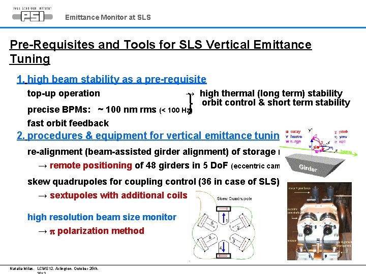
Emittance Monitor at SLS Pre-Requisites and Tools for SLS Vertical Emittance Tuning 1. high beam stability as a pre-requisite top-up operation → high thermal (long term) stability orbit control & short term stability precise BPMs: ~ 100 nm rms (< 100 Hz) fast orbit feedback 2. procedures & equipment for vertical emittance tuning re-alignment (beam-assisted girder alignment) of storage ring → remote positioning of 48 girders in 5 Do. F (eccentric cam shafts drives) skew quadrupoles for coupling control (36 in case of SLS) → sextupoles with additional coils high resolution beam size monitor → p polarization method Natalia Milas, LCWS 12, Arlington, October 25 th,
Emittance Monitor at SLS Procedure for SLS Vertical Emittance Tuning 1. measurement and correction of BPM roll error → avoid “fake” vertical dispersion readings (from 48 dispersive BPMs with hhor ≠ 0) 2. realignment of magnet girder to remove main sources of vertical dispersion → reduction of rms vertical correction kick from ~ 130 mrad to ~ 50 mrad 3. meas. & correction of vertical dispersion and betatron coupling → model-based skew quadrupole corrections (12 dispersive and 24 nondispersive skew quads) 4. meas. & correction of vertical dispersion, betatron coupling and linear optics → model-based skew quadrupole corrections and orbit bumbs 5. “random walk” optimization of vertical beam size Natalia Milas, LCWS 12, Arlington, October 25 th,
- Slides: 20