
Slope Stabilization Using Soil Nails Canterbury 14719 Joseph

Slope Stabilization Using Soil Nails (Canterbury 14719) Joseph R. Blair, P. E. NHDOT – Geotechnical Section
Presentation Outline I. The site and its history II. How the project evolved III. How I modeled the slope and soil nails IV. Why the soil nail alternative was selected V. Construction phase
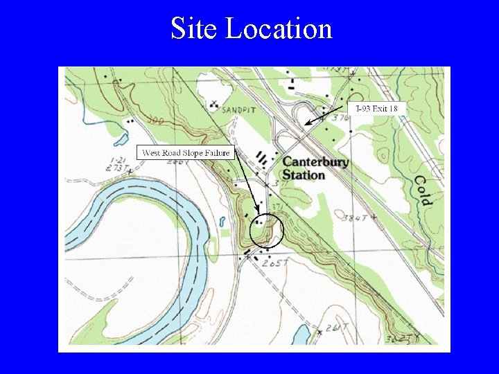
Site Location
History of Maintenance Issues • Leaning guardrail – Vehicle impacts – Snow plow impacts – Creeping slope • Cracks in roadway pavement • Occasional pavement shim at shoulder
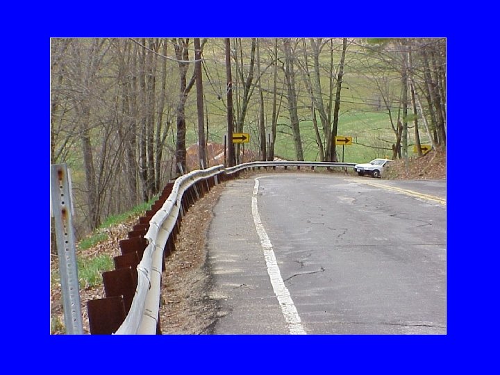
Year 2000 - Recommendations • Need to control surface runoff – Construct curbing and collection system • Reconstruct the roadway base • Install transverse and longitudinal underdrain
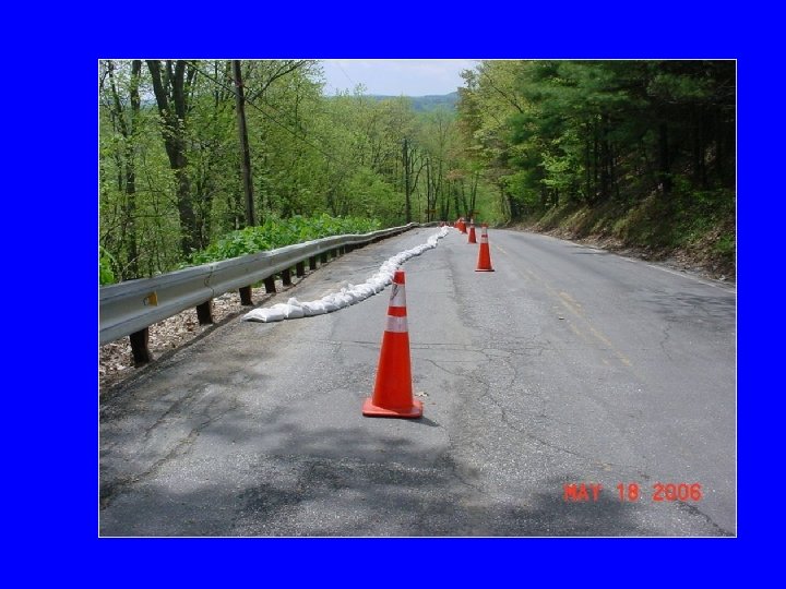
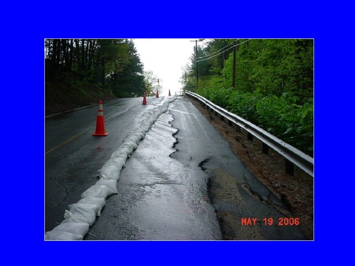
Mother’s Day Storm - 2006 • +/-10 in. rain in 24 hrs • District 5 calls the Geotechnical Section requesting assistance
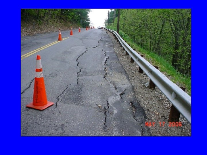
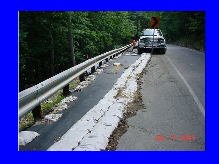
On-Site Assessment • Slope failure – Visible 300 ft length in roadway • One travel lane must remain closed • Alternating one-way traffic is acceptable • Use sand bags to divert water from cracks
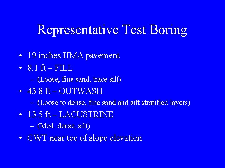
Representative Test Boring • 19 inches HMA pavement • 8. 1 ft – FILL – (Loose, fine sand, trace silt) • 43. 8 ft – OUTWASH – (Loose to dense, fine sand silt stratified layers) • 13. 5 ft – LACUSTRINE – (Med. dense, silt) • GWT near toe of slope elevation

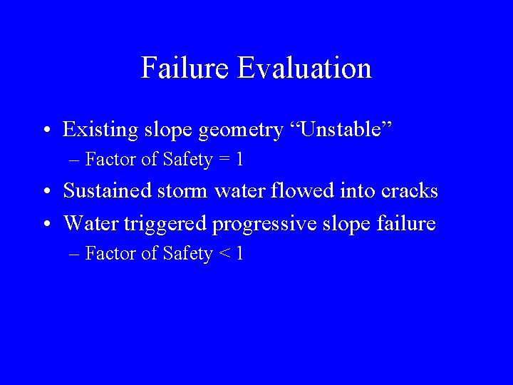
Failure Evaluation • Existing slope geometry “Unstable” – Factor of Safety = 1 • Sustained storm water flowed into cracks • Water triggered progressive slope failure – Factor of Safety < 1
What Are Some Alternatives to Fix the Roadway? • “Assume District 5 maintenance forces will perform the work” • “Assume there are no project constraints”
2 H: 1 V Alternative • Remove failure mass • Flatten slope to 2 H: 1 V • No special slope treatments

1. 5 H: 1 V Alternative • • Remove failure mass Flatten slope to 1. 5 H: 1 V Biaxial geogrid at slope face Less impact beyond toe of slope

Construction Impacts • ROW – 3 rod road – Right side offset at 24. 5 ft • Abutter – Gold Star Sod Farms, Inc. • Easement – Society for the Protection of NH Forests (SPNHF) holds a conservation easement – Land Community Heritage Investment Program (LCHIP) funded the easement
Revised Design Constraints • No temp. /permanent impacts beyond ROW • Try to avoid temporary utility relocations
Sheetpile Alternative • Very long sheet lengths required – Assumed location of failure plane – Steep sloping ground • Temporary relocation of utilities required • Road closure required

MSE Alternative • Geogrid attached to L-shaped wire baskets • Wire baskets stacked vertically below FG • Wire baskets stepped 6 inches above FG

MSE Alternative (continued) • • Base of MSE below assumed failure plane Temporary relocation of utilities likely Road closure required Erosion control concerns

Public Hearing • Sheetpiles presented as preferred alternative • Road closure – 12 mile detour – 1 month duration • Feedback – Road closure is unacceptable – Serious concern for emergency response delays

Revised Design Constraints (#2) • No temp. /permanent impacts beyond ROW • Must avoid temporary utility relocations • Must maintain alternating one-way traffic

Invite Soil Nail Launcher (SNL) to present their system
SNL Visit • • “Launched Nail” Presentation NHDOT provided test boring logs Visited the site At the site, SNL discussed “Supernails” – Drilled and grouted soil nail • No drilling equipment on slope • Provided two design alternatives
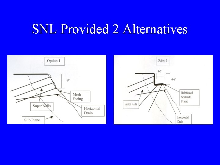
SNL Provided 2 Alternatives
SNL • • • Made good first impression Very concerned about reputation Claimed 100% success rate Guaranteed work Provided many references

Soil Nails for Slope Stabilization • How does this type of soil nail work? • What is the capacity of a soil nail? • How can I model the stabilizing effect?

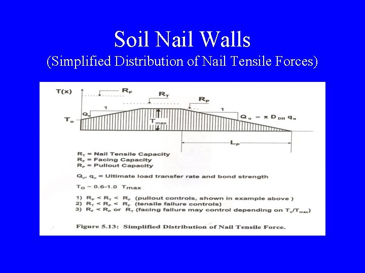
Soil Nail Walls (Simplified Distribution of Nail Tensile Forces)

Not constructing a soil nail wall




Estimated Bond Strength (k. Pa) (Elias and Juran, 1991)
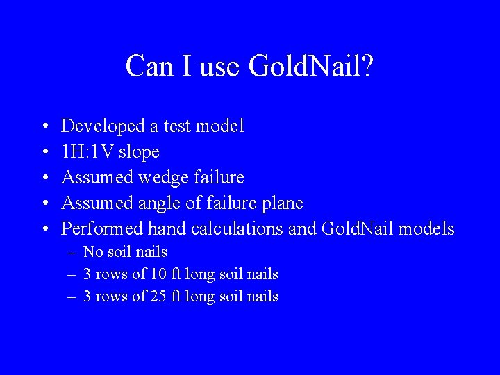
Can I use Gold. Nail? • • • Developed a test model 1 H: 1 V slope Assumed wedge failure Assumed angle of failure plane Performed hand calculations and Gold. Nail models – No soil nails – 3 rows of 10 ft long soil nails – 3 rows of 25 ft long soil nails
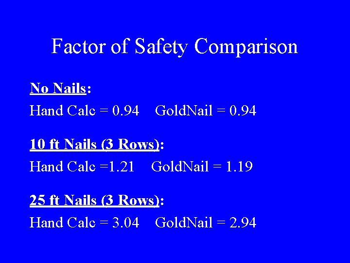
Factor of Safety Comparison No Nails: Hand Calc = 0. 94 Gold. Nail = 0. 94 10 ft Nails (3 Rows): Hand Calc =1. 21 Gold. Nail = 1. 19 25 ft Nails (3 Rows): Hand Calc = 3. 04 Gold. Nail = 2. 94
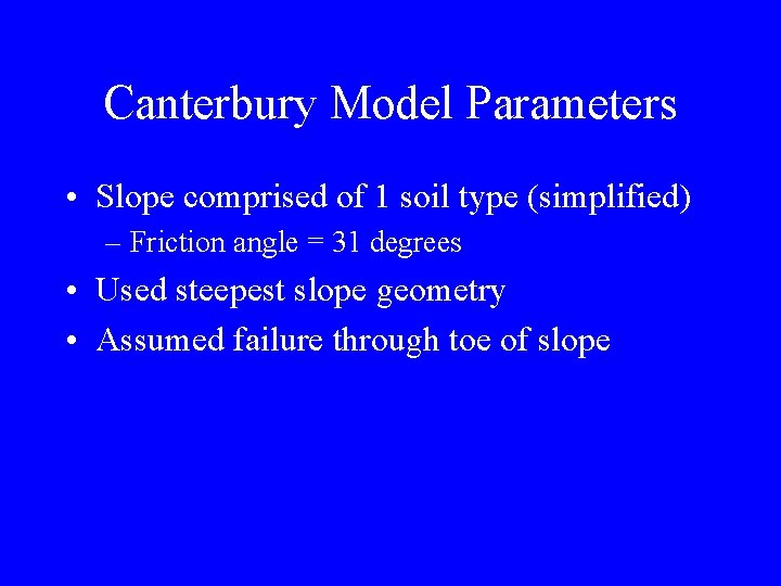
Canterbury Model Parameters • Slope comprised of 1 soil type (simplified) – Friction angle = 31 degrees • Used steepest slope geometry • Assumed failure through toe of slope
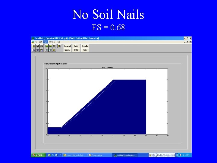
No Soil Nails FS = 0. 68
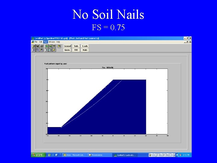
No Soil Nails FS = 0. 75
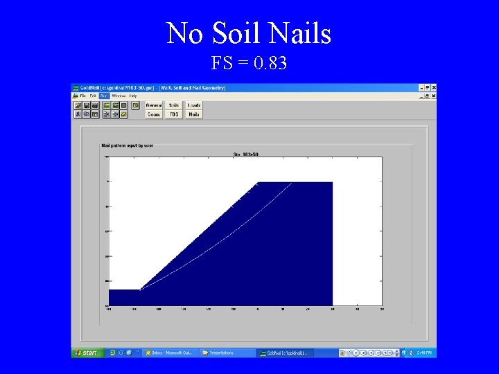
No Soil Nails FS = 0. 83
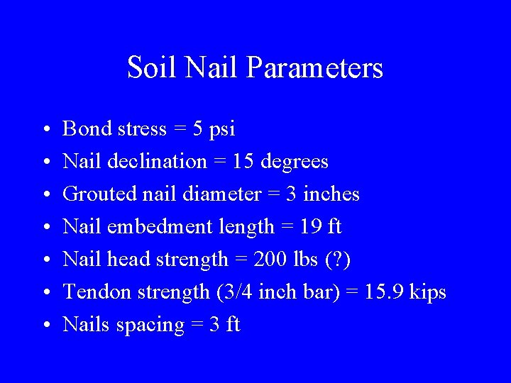
Soil Nail Parameters • • Bond stress = 5 psi Nail declination = 15 degrees Grouted nail diameter = 3 inches Nail embedment length = 19 ft Nail head strength = 200 lbs (? ) Tendon strength (3/4 inch bar) = 15. 9 kips Nails spacing = 3 ft

4 Rows of Soil Nails FS = 0. 84
4 Rows of Soil. Nails FS = 0. 94
4 Rows of Soil. Nails FS = 0. 95
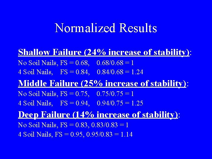
Normalized Results Shallow Failure (24% increase of stability): No Soil Nails, FS = 0. 68, 0. 68/0. 68 = 1 4 Soil Nails, FS = 0. 84, 0. 84/0. 68 = 1. 24 Middle Failure (25% increase of stability): No Soil Nails, FS = 0. 75, 0. 75/0. 75 = 1 4 Soil Nails, FS = 0. 94, 0. 94/0. 75 = 1. 25 Deep Failure (14% increase of stability): No Soil Nails, FS = 0. 83, 0. 83/0. 83 = 1 4 Soil Nails, FS = 0. 95, 0. 95/0. 83 = 1. 14
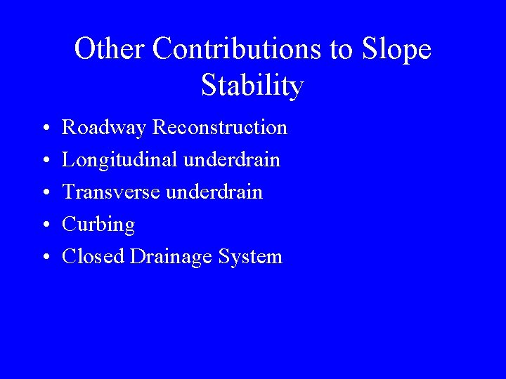
Other Contributions to Slope Stability • • • Roadway Reconstruction Longitudinal underdrain Transverse underdrain Curbing Closed Drainage System
4 Rows of Soil Nails Required • Bottom row of soil nails beyond the ROW • Minimal tree cutting required • LCHIP allowed construction impacts
Target Factor of Safety • The existing slope configuration was less than the generally accepted range of 1. 3 to 1. 5 • The design shouldn’t overcompensate to dramatically improve slope stability • Concluded: The soil nail alternative would provide a nominal increase to the preconstruction safety factor
Revised Geotechnical Alternatives • Soil Nails – Installed from roadway surface with no equipment on the slope • Geopier – Similar construction impacts as MSE alternative • Shored Mechanically Stabilized Earth Wall System (SMSE) – Quickly ruled out due to expense
nd 2 • • Public Hearing Soil Nails presented as preferred alternative No detour proposed No temporary road closures Very positive response from attendees
Final Design • 3 separate soil nail treatment segments – 1 slope repair (drilled & grouted soil nails) – 2 preventative treatment • 1 with launched soil nails • 1 with drilled & grouted soil nails • Developed typical sections • Developed specifications
Slope Repair Segment

Preventative Treatment Segments
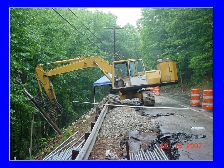
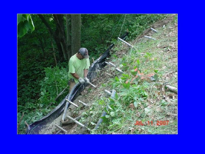
Construction Phase • Prime Contractor: Weaver Brothers • Soil Nail Item Sub-Contractor: SNL • Construction starts: July 2007

Slope Repair Segment Drilled and grouted soil nails (SNL – Super Nails)
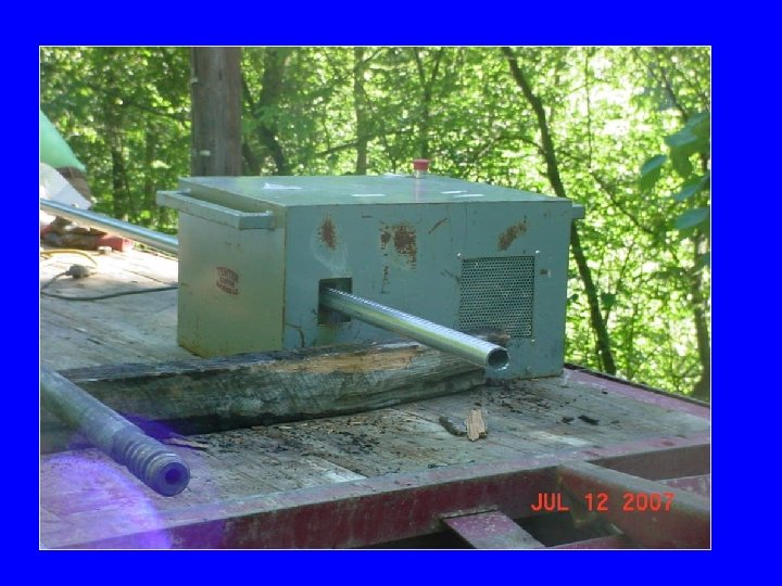
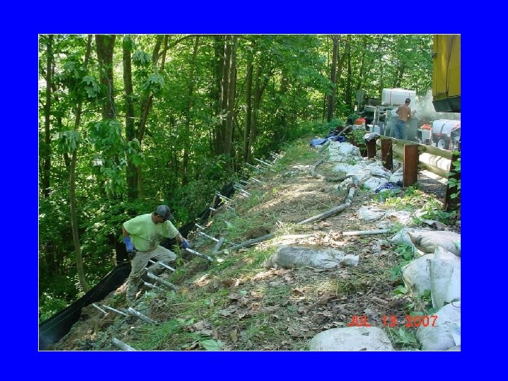
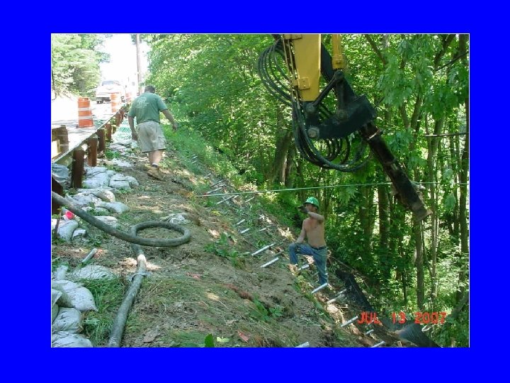

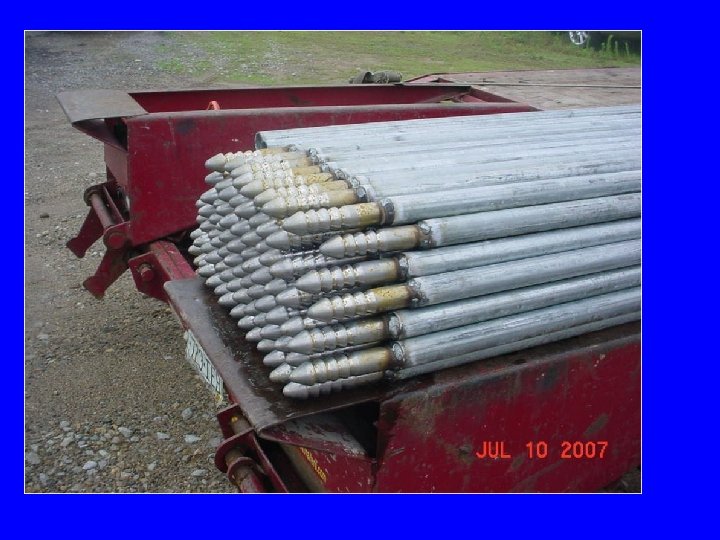
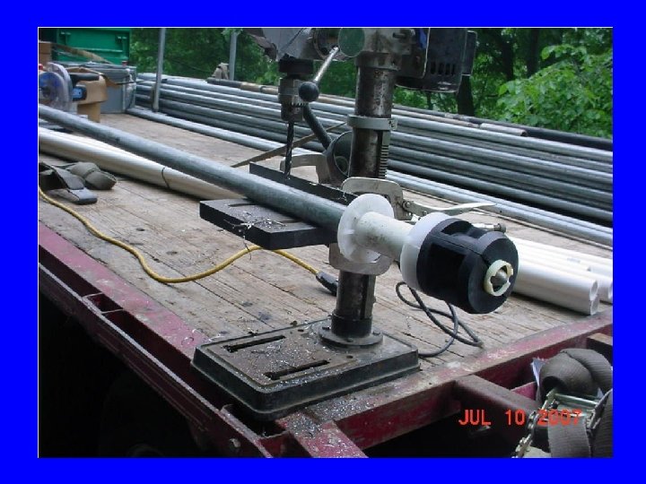
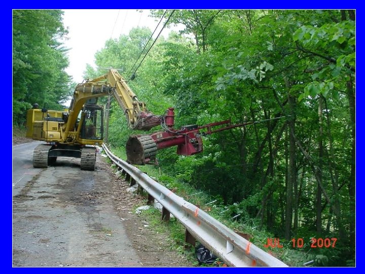
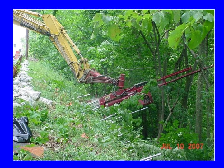
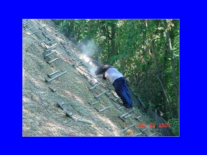
Preventative Treatment Segment Launched soil nails (SNL – Soil Nail Launcher)
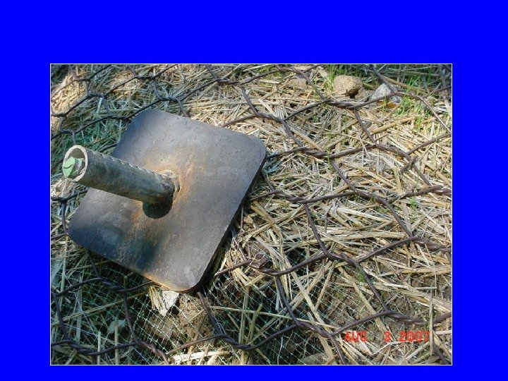
Soil Nail Facing • All segments received same facing • Facing components – Grass seed – Erosion matting – Wire mesh – Bearing plate
Pullout Tests • 3 Drilled and Grouted Soil Nails • 1 Launched Soil Nail
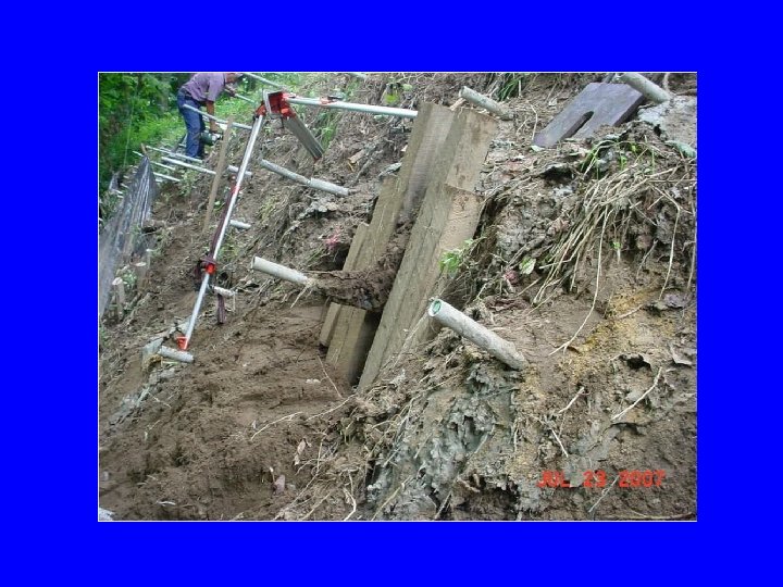
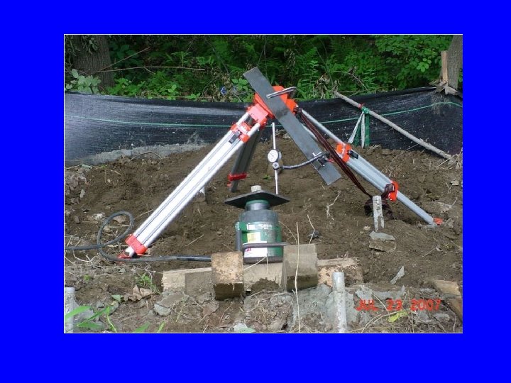
Test Results • Average Bond Stress 4. 3 psi • Pullout Capacities – Drilled and Grouted: 562 lbs/ft – Launched and Grouted: 241 lbs/ft
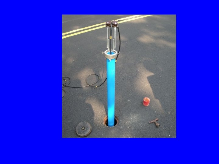
Post Construction Monitoring • 2 inclinometers installed – Sta. 103+00, Right 9 – Sta. 104+50, Right 9


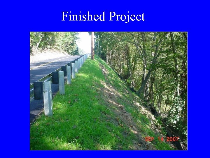
Finished Project
Bid Prices of Soil Nail Items • Drilled and Grouted, 20 ft Soil Nail – Quantity = 392 – $525 each • Drilled & Grouted – 14 ft Soil Nail – Quantity = 18 – $520 each • Launched – 14 ft Soil Nail – Quantity = 75 – $475 each
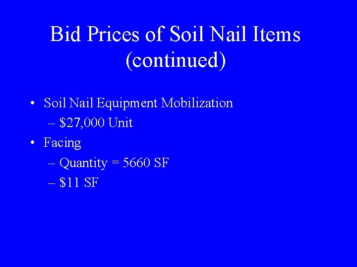
Bid Prices of Soil Nail Items (continued) • Soil Nail Equipment Mobilization – $27, 000 Unit • Facing – Quantity = 5660 SF – $11 SF
- Slides: 87