
Slide 1 Fig 32 CO p 1003 As
- Slides: 42
Slide 1 Fig 32 -CO, p. 1003
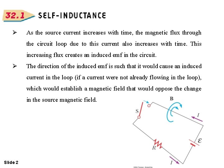
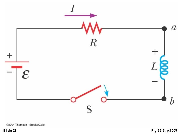
Ø As the source current increases with time, the magnetic flux through the circuit loop due to this current also increases with time. This increasing flux creates an induced emf in the circuit. Ø The direction of the induced emf is such that it would cause an induced current in the loop (if a current were not already flowing in the loop), which would establish a magnetic field that would oppose the change in the source magnetic field. Slide 2
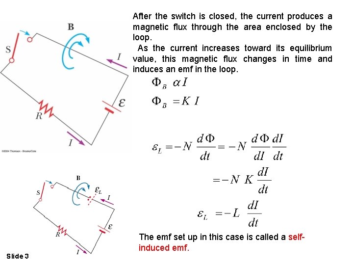
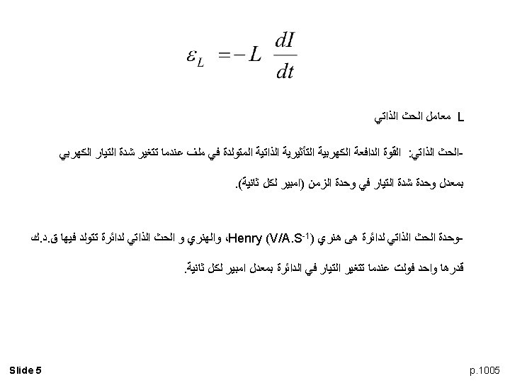
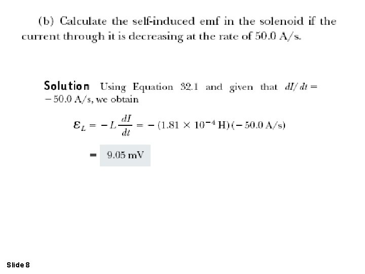
After the switch is closed, the current produces a magnetic flux through the area enclosed by the loop. As the current increases toward its equilibrium value, this magnetic flux changes in time and induces an emf in the loop. The emf set up in this case is called a selfinduced emf. Slide 3
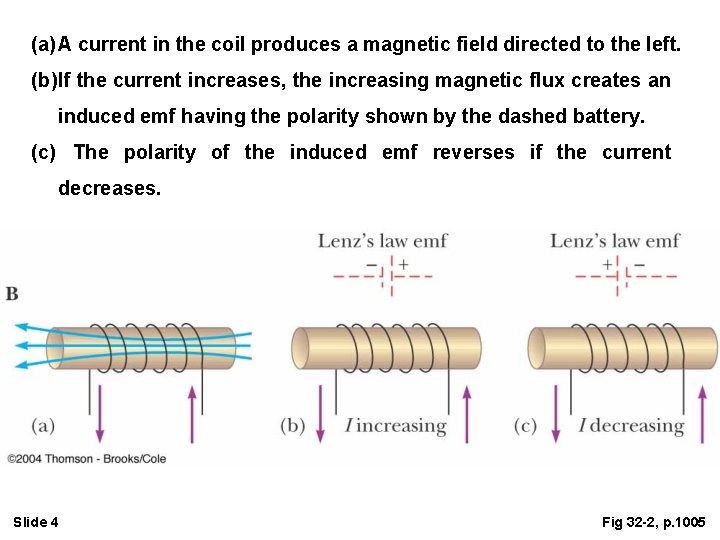
(a) A current in the coil produces a magnetic field directed to the left. (b) If the current increases, the increasing magnetic flux creates an induced emf having the polarity shown by the dashed battery. (c) The polarity of the induced emf reverses if the current decreases. Slide 4 Fig 32 -2, p. 1005
Slide 6
Slide 7
Slide 8
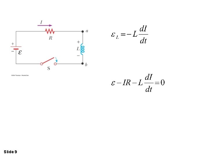
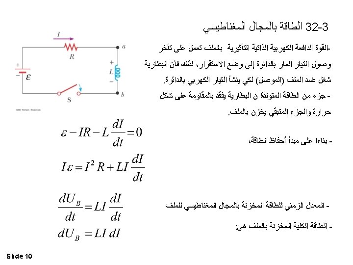
Slide 9
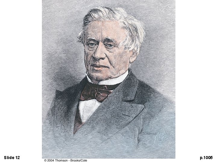
Slide 12 p. 1005
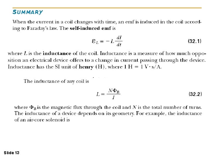
Slide 13
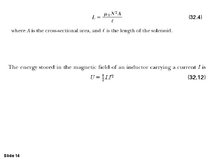
Slide 14
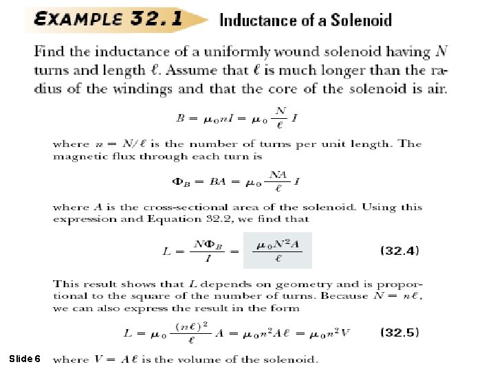
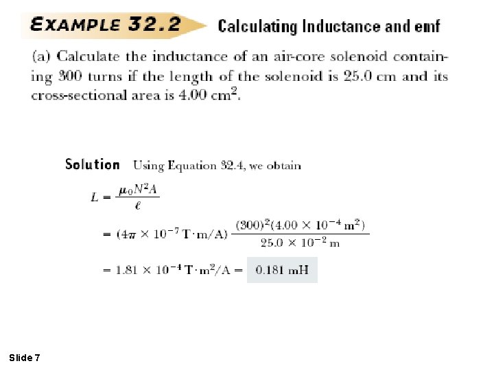
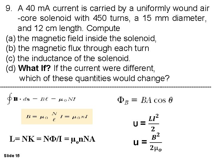
9. A 40 m. A current is carried by a uniformly wound air -core solenoid with 450 turns, a 15 mm diameter, and 12 cm length. Compute (a) the magnetic field inside the solenoid, (b) the magnetic flux through each turn (c) the inductance of the solenoid. (d) What If? If the current were different, which of these quantities would change? ----------------------------------------------------------- L= NK = NФ/I = µon. NA Slide 15
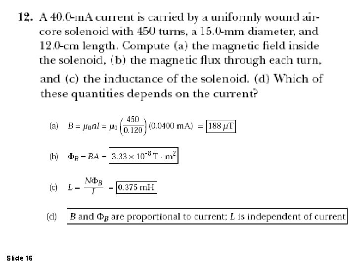
Slide 16
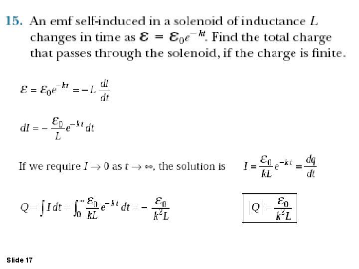
Slide 17
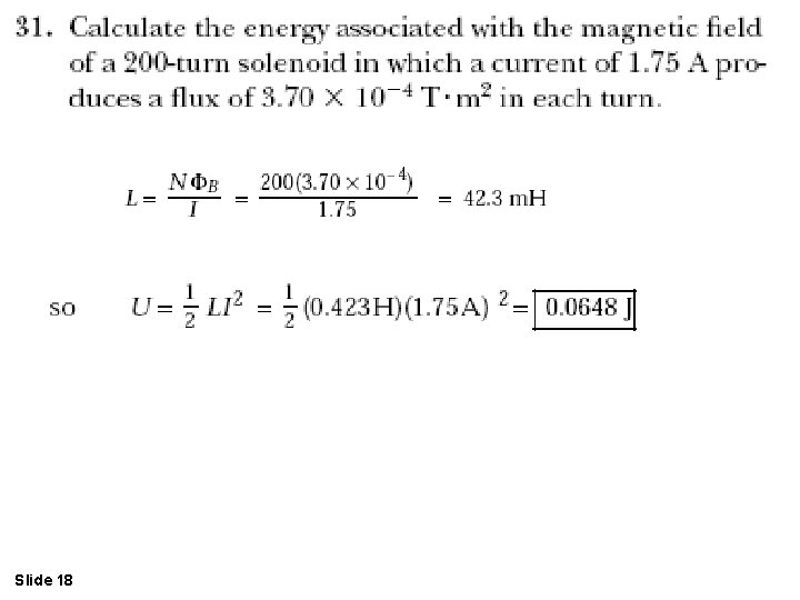
Slide 18
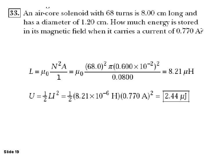
Slide 19
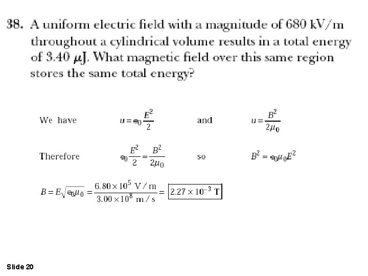
Slide 20
Slide 21 Fig 32 -3, p. 1007
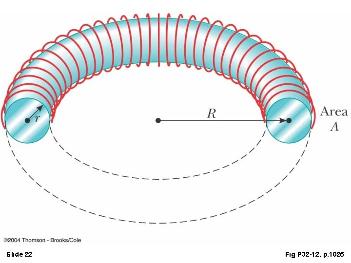
Slide 22 Fig P 32 -12, p. 1025
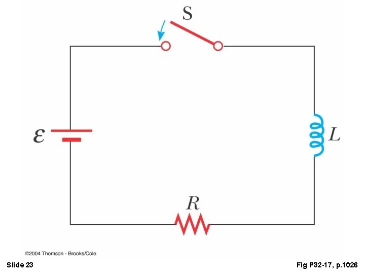
Slide 23 Fig P 32 -17, p. 1026
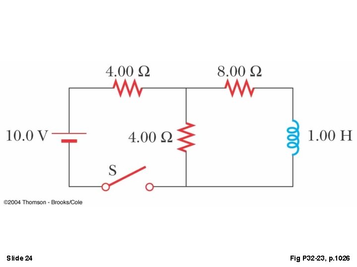
Slide 24 Fig P 32 -23, p. 1026
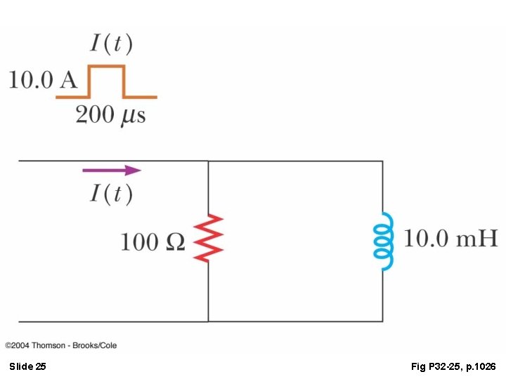
Slide 25 Fig P 32 -25, p. 1026
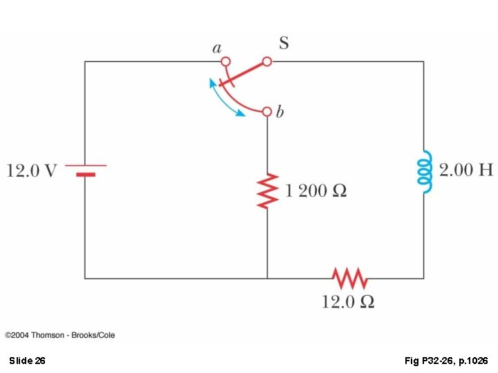
Slide 26 Fig P 32 -26, p. 1026
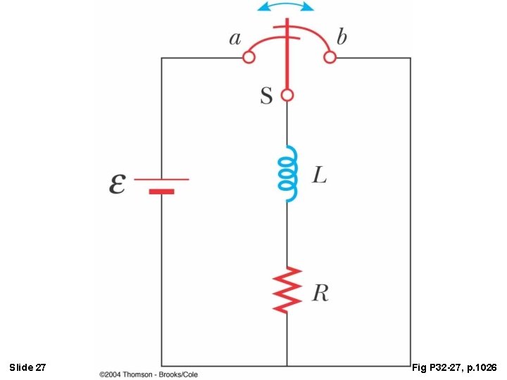
Slide 27 Fig P 32 -27, p. 1026
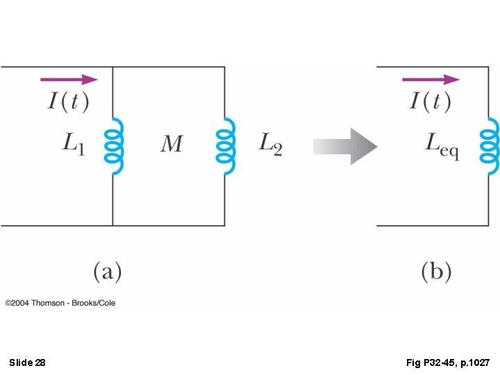
Slide 28 Fig P 32 -45, p. 1027
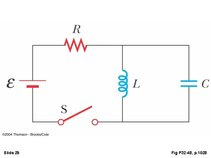
Slide 29 Fig P 32 -48, p. 1028
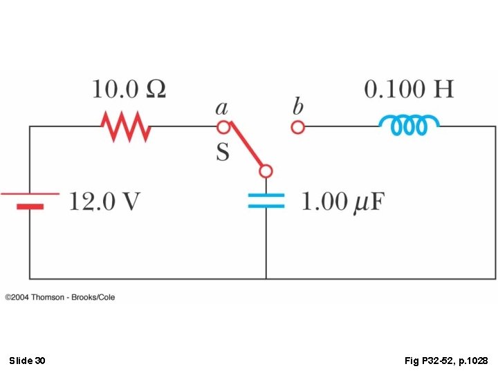
Slide 30 Fig P 32 -52, p. 1028
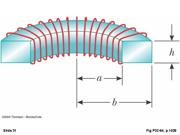
Slide 31 Fig P 32 -64, p. 1029
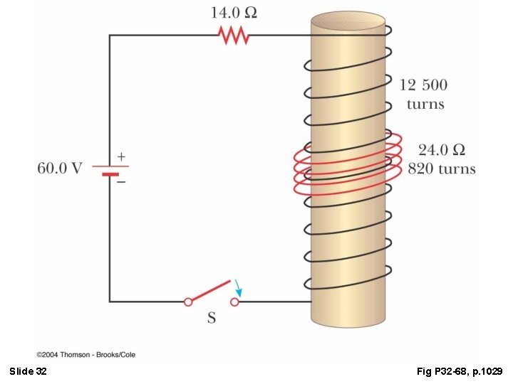
Slide 32 Fig P 32 -68, p. 1029
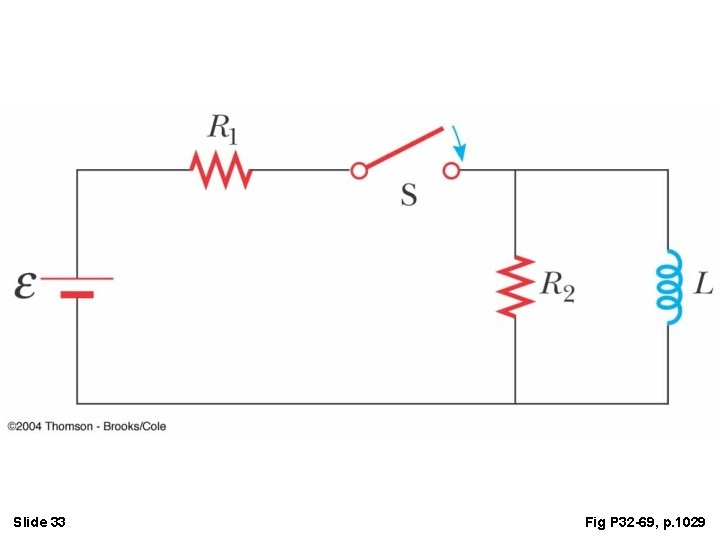
Slide 33 Fig P 32 -69, p. 1029
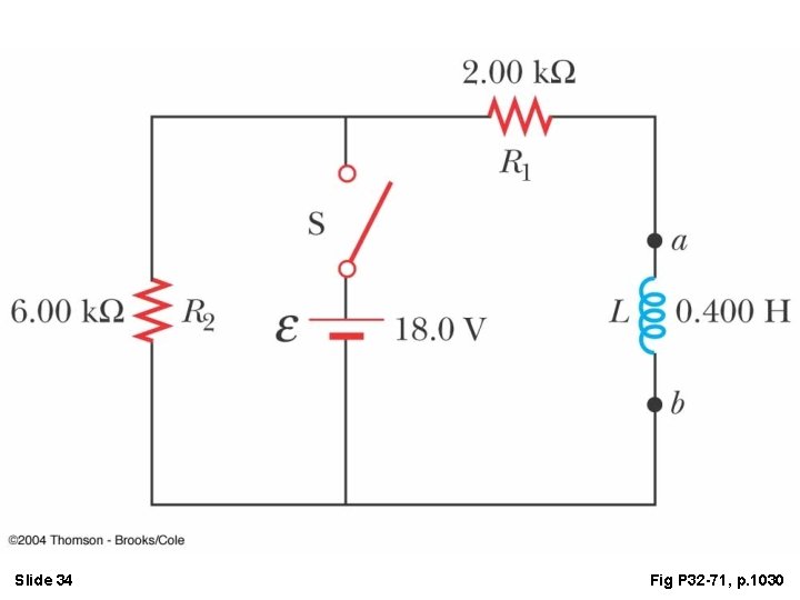
Slide 34 Fig P 32 -71, p. 1030
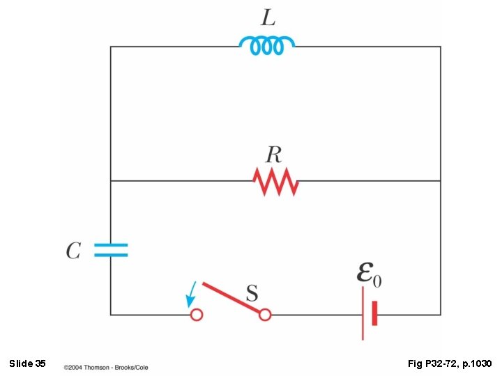
Slide 35 Fig P 32 -72, p. 1030
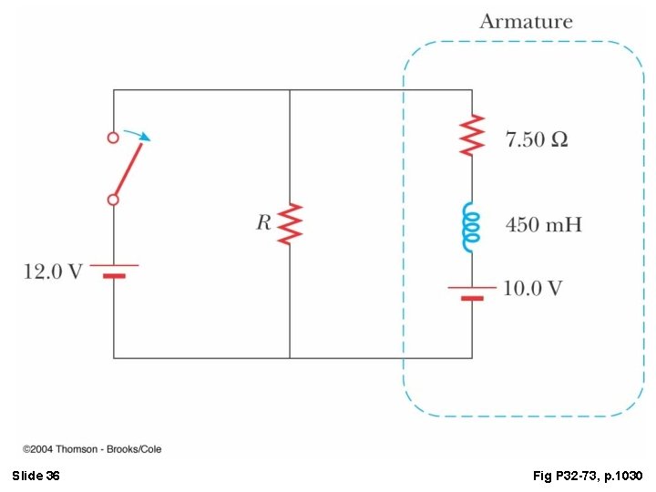
Slide 36 Fig P 32 -73, p. 1030
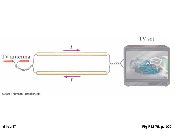
Slide 37 Fig P 32 -75, p. 1030
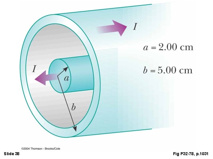
Slide 38 Fig P 32 -78, p. 1031
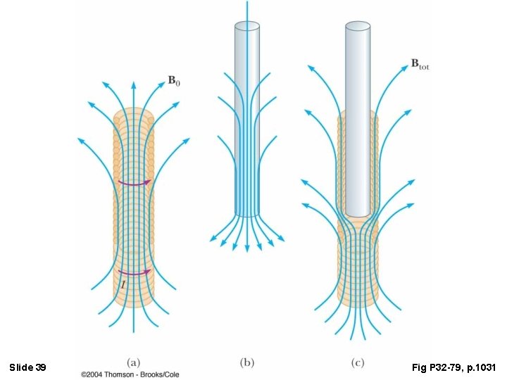
Slide 39 Fig P 32 -79, p. 1031
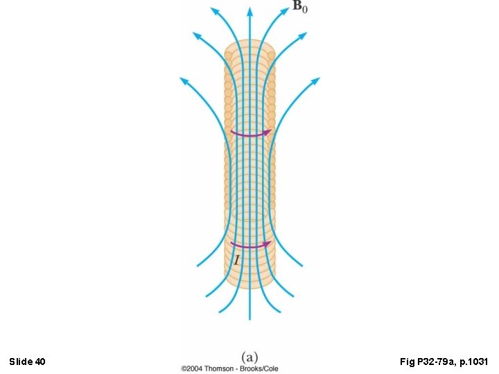
Slide 40 Fig P 32 -79 a, p. 1031
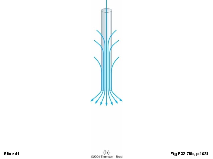
Slide 41 Fig P 32 -79 b, p. 1031
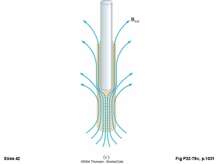
Slide 42 Fig P 32 -79 c, p. 1031