
SLHC tracker upgrade challenges and strategies in ATLAS



- Slides: 44
SLHC tracker upgrade: challenges and strategies in ATLAS Marc Weber (RAL) What, why, how ? Main challenges: material; power; cost Can we do it ? Yes! Vertex 2007, September 2007, Lake Placid, NY, USA 1
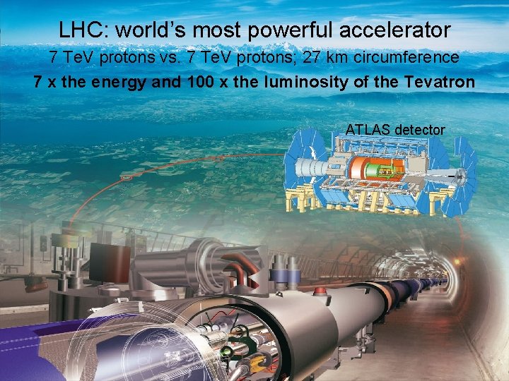
LHC: world’s most powerful accelerator 7 Te. V protons vs. 7 Te. V protons; 27 km circumference 7 x the energy and 100 x the luminosity of the Tevatron ATLAS detector 2
What is SLHC ? • Super-LHC: LHC luminosity upgrade • Target: ten-fold increase of luminosity/year over LHC by ~2016 • Highest priority in PP European Strategy Roadmap approved by CERN Council in 2006 • Cost: ~ 1 B€ 3
Why upgrade the LHC ? After all, LHC should have made major discoveries by 2015 already Three generic physics reasons • Consolidation of LHC discoveries • Extended discovery reach (~30% in mass or ~1 Te. V) • Increased precision and access to rare decays/channels There are detailed studies assuming specific scenarios (Higgs, Susy, extra-dimensions, Z’, …). We expect to know which of these nature has chosen before starting tracker mass production 4
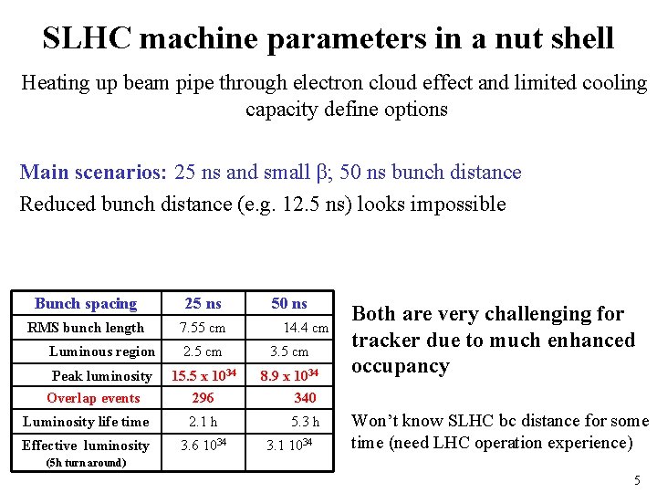
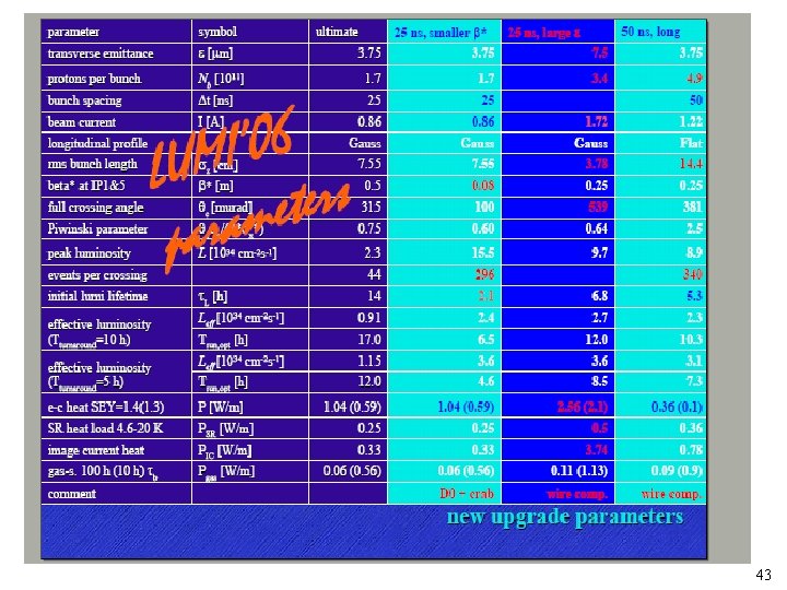
SLHC machine parameters in a nut shell Heating up beam pipe through electron cloud effect and limited cooling capacity define options Main scenarios: 25 ns and small β; 50 ns bunch distance Reduced bunch distance (e. g. 12. 5 ns) looks impossible Bunch spacing 25 ns RMS bunch length 7. 55 cm 50 ns 14. 4 cm Luminous region 2. 5 cm 3. 5 cm Peak luminosity 15. 5 x 1034 8. 9 x 1034 Overlap events 296 340 Luminosity life time 2. 1 h 5. 3 h Effective luminosity 3. 6 1034 3. 1 1034 Both are very challenging for tracker due to much enhanced occupancy Won’t know SLHC bc distance for some time (need LHC operation experience) (5 h turn around) 5
Detector upgrades are different • Less time, money, and man-power for R&D Commissioning, operation, and exploitation of LHC is first priority • Constraints due to existing detector volume, infrastructure, services… • Limited shut-down and installation period 6
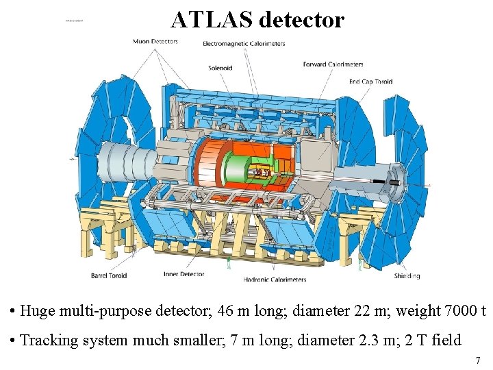
ATLAS detector • Huge multi-purpose detector; 46 m long; diameter 22 m; weight 7000 t • Tracking system much smaller; 7 m long; diameter 2. 3 m; 2 T field 7
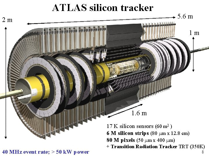
ATLAS silicon tracker 2 m 5. 6 m 1 m 1. 6 m 17 K silicon sensors (60 m 2 ) 6 M silicon strips (80 m x 12. 8 cm) 80 M pixels (50 m x 400 m) 40 MHz event rate; > 50 k. W power + Transition Radiation Tracker TRT (350 K) 8
Disclaimer This talk is mostly about silicon strip technology, not pixels Upgrade R&D is still at early stage Focus on challenges and will present concepts for addressing them. Will be short on details and numbers. Some concepts and ideas might well be unpractical, not affordable or simply wrong Goal is to produce ATLAS Tracker Upgrade TDR within 3 years. We have a process and an organizational structure to get there, but that’s not part of the talk. 9
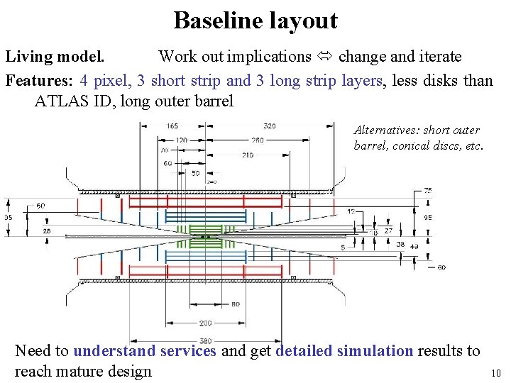
Baseline layout Living model. Work out implications change and iterate Features: 4 pixel, 3 short strip and 3 long strip layers, less disks than ATLAS ID, long outer barrel Alternatives: short outer barrel, conical discs, etc. Need to understand services and get detailed simulation results to reach mature design 10
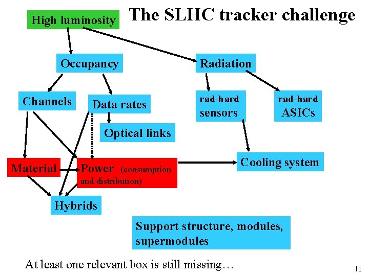
High luminosity The SLHC tracker challenge Occupancy Channels Radiation Data rates rad-hard sensors ASICs Optical links Material Power (consumption and distribution) Cooling system Hybrids Support structure, modules, supermodules At least one relevant box is still missing… 11
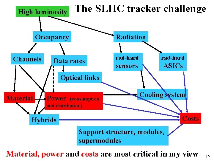
High luminosity The SLHC tracker challenge Occupancy Channels Radiation Data rates rad-hard sensors ASICs Optical links Material Power (consumption and distribution) Cooling system Costs Hybrids Support structure, modules, supermodules Material, power and costs are most critical in my view 12
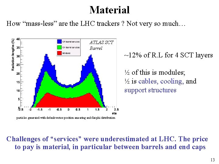
Material How “mass-less” are the LHC trackers ? Not very so much… ATLAS SCT Barrel ~12% of R. L for 4 SCT layers ½ of this is modules; ½ is cables, cooling, and support structures particles generated with default vertex position smearing and flat phi distribution Challenges of “services” were underestimated at LHC. The price to pay is material, in particular between barrels and end caps 13
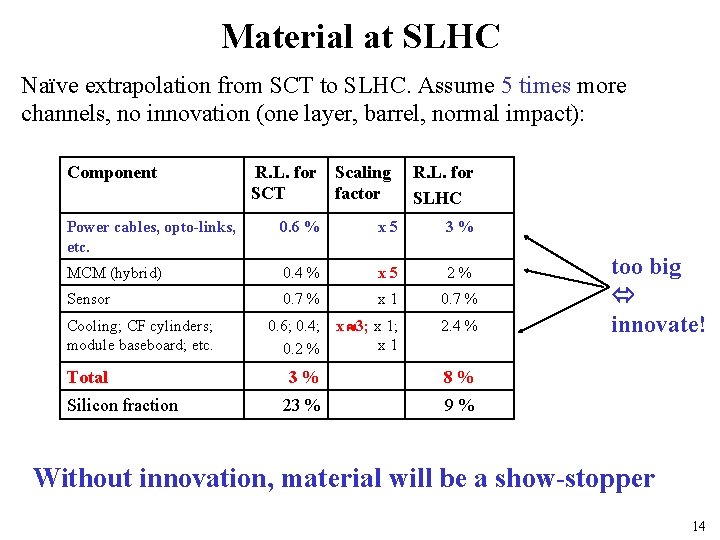
Material at SLHC Naïve extrapolation from SCT to SLHC. Assume 5 times more channels, no innovation (one layer, barrel, normal impact): Component R. L. for SCT Scaling factor R. L. for SLHC Power cables, opto-links, etc. 0. 6 % x 5 3% MCM (hybrid) 0. 4 % x 5 2% Sensor 0. 7 % x 1 0. 7 % 0. 6; 0. 4; x 3; x 1 0. 2 % 2. 4 % Cooling; CF cylinders; module baseboard; etc. Total Silicon fraction 3% 8% 23 % 9% too big innovate! Without innovation, material will be a show-stopper 14
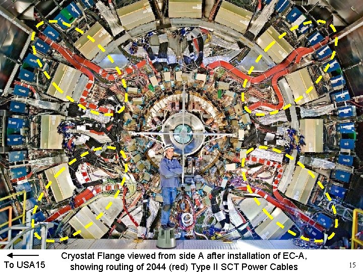
To USA 15 Cryostat Flange viewed from side A after installation of EC-A, showing routing of 2044 (red) Type II SCT Power Cables 15
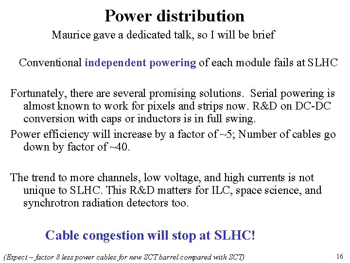
Power distribution Maurice gave a dedicated talk, so I will be brief Conventional independent powering of each module fails at SLHC Fortunately, there are several promising solutions. Serial powering is almost known to work for pixels and strips now. R&D on DC-DC conversion with caps or inductors is in full swing. Power efficiency will increase by a factor of ~5; Number of cables go down by factor of ~40. The trend to more channels, low voltage, and high currents is not unique to SLHC. This R&D matters for ILC, space science, and synchrotron radiation detectors too. Cable congestion will stop at SLHC! (Expect ~ factor 8 less power cables for new SCT barrel compared with SCT) 16
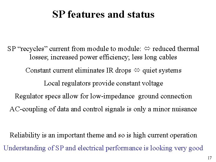
SP features and status SP “recycles” current from module to module: reduced thermal losses; increased power efficiency; less long cables Constant current eliminates IR drops quiet systems Local regulators provide constant voltage Regulator specs allow for low-impedance ground connection AC-coupling of data and control signals is only a minor nuisance Reliability is an important theme and so is high current operation Understanding of SP and electrical performance is looking very good 17
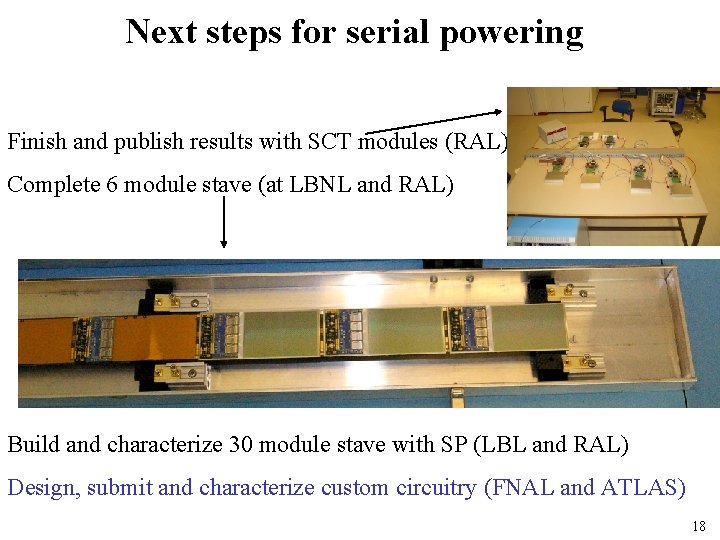
Next steps for serial powering Finish and publish results with SCT modules (RAL) Complete 6 module stave (at LBNL and RAL) Build and characterize 30 module stave with SP (LBL and RAL) Design, submit and characterize custom circuitry (FNAL and ATLAS) 18
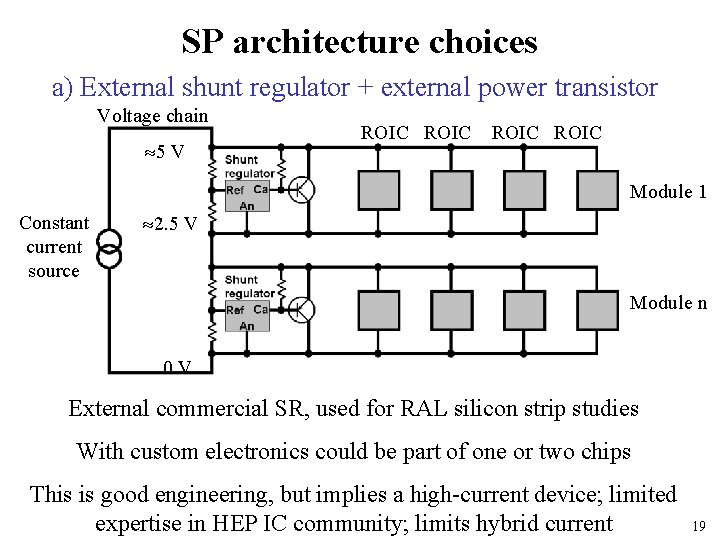
SP architecture choices a) External shunt regulator + external power transistor Voltage chain 5 V ROIC Module 1 Constant current source 2. 5 V Module n 0 V External commercial SR, used for RAL silicon strip studies With custom electronics could be part of one or two chips This is good engineering, but implies a high-current device; limited expertise in HEP IC community; limits hybrid current 19
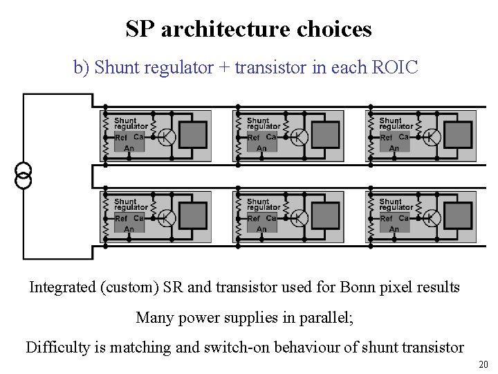
SP architecture choices b) Shunt regulator + transistor in each ROIC Integrated (custom) SR and transistor used for Bonn pixel results Many power supplies in parallel; Difficulty is matching and switch-on behaviour of shunt transistor 20
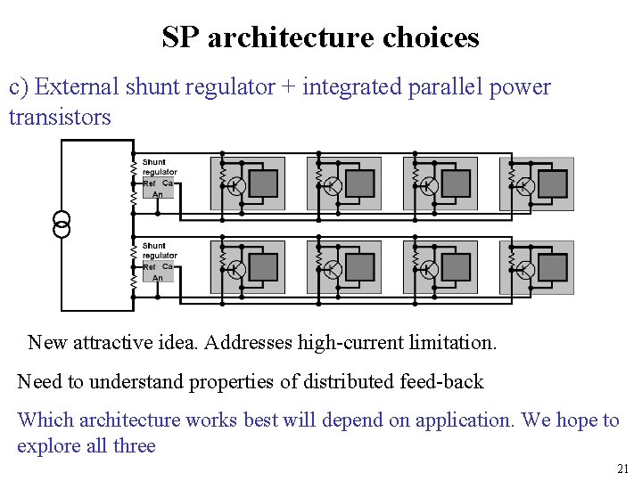
SP architecture choices c) External shunt regulator + integrated parallel power transistors New attractive idea. Addresses high-current limitation. Need to understand properties of distributed feed-back Which architecture works best will depend on application. We hope to explore all three 21
Let’s get there in time! • HEP experience with high-power IC design is limited • Man-power is limited (LHC is first priority) • Power distribution scheme and total power consumption will shape the new trackers power R&D is very urgent • Any solution will need to be explored on advanced detector prototypes before being accepted costs Need efficient collaboration and communication (across experiments/colliders, between engineers/physicists) There is significant interest in dedicated power distribution R&D initiative 22
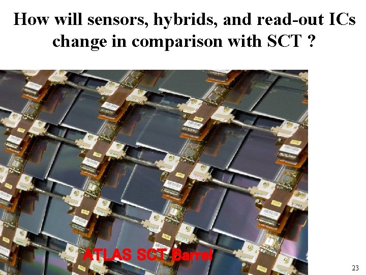
How will sensors, hybrids, and read-out ICs change in comparison with SCT ? ATLAS SCT Barrel 23
Radiation-hard silicon sensors Need sensors withstanding ~ 1015 n/cm 2 for inner silicon strip layers n-on p sensors look fine. Intense R&D effort. See talk of Gianluigi How do sensor requirements influence overall system? • Cool sensors to less than -25 C to limit radiation-induced leakage current major impact on cooling system (see below) • Radiation-induced type inversion requires increased depletion voltage (watch micro-discharge) and leads to reduced signal low-noise preamp; comparator; HV cable ratings • Different signal polarity (electrons instead of holes) reduces charge trapping affects design of read-out IC 24
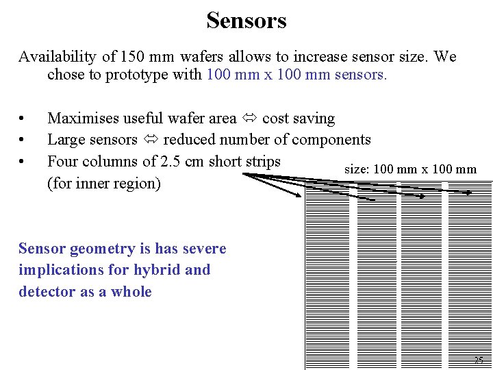
Sensors Availability of 150 mm wafers allows to increase sensor size. We chose to prototype with 100 mm x 100 mm sensors. • • • Maximises useful wafer area cost saving Large sensors reduced number of components Four columns of 2. 5 cm short strips size: 100 mm x 100 mm (for inner region) Sensor geometry is has severe implications for hybrid and detector as a whole 25
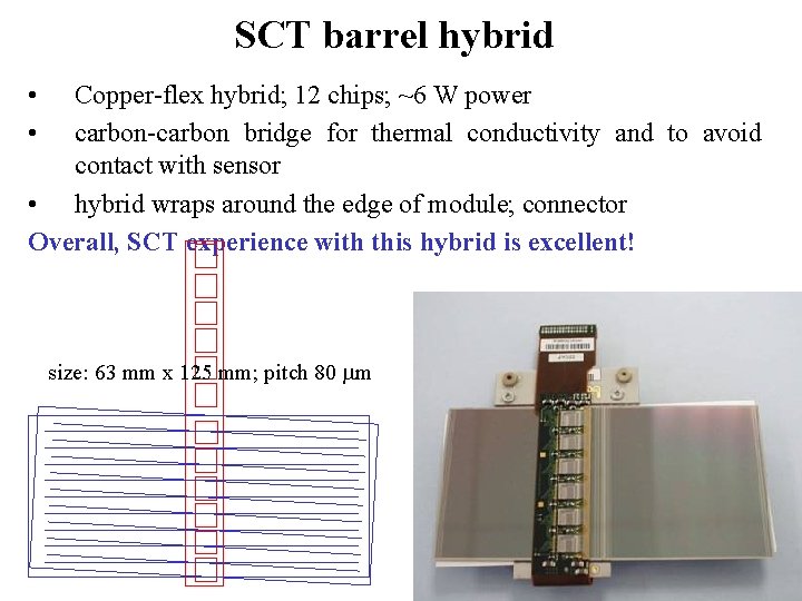
SCT barrel hybrid • • Copper-flex hybrid; 12 chips; ~6 W power carbon-carbon bridge for thermal conductivity and to avoid contact with sensor • hybrid wraps around the edge of module; connector Overall, SCT experience with this hybrid is excellent! size: 63 mm x 125 mm; pitch 80 m 26
SLHC hybrids SLHC aggravates a number of old difficulties • • More channels more and wider hybrids material More channels more power per hybrid – – • More channels increase data bandwidth – – – • Power distribution challenge; local power supply challenge Thermal management Chose between more data lines off hybrid or Higher data/clock frequencies controlled impedance design, “cross talk” Optical links Not clear if “hybridge” over sensor a la SCT is still feasible 27
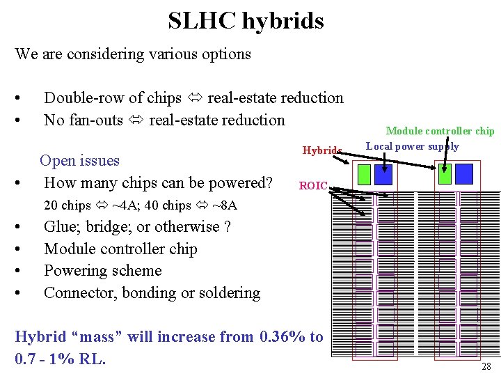
SLHC hybrids We are considering various options • • • Double-row of chips real-estate reduction No fan-outs real-estate reduction Open issues How many chips can be powered? Hybrids Module controller chip Local power supply ROIC 20 chips ~4 A; 40 chips ~8 A • • Glue; bridge; or otherwise ? Module controller chip Powering scheme Connector, bonding or soldering Hybrid “mass” will increase from 0. 36% to 0. 7 - 1% RL. 28
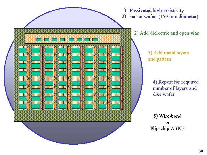
Poor man’s 3 D approach Considering two options a) Thin film-silicon interposer (= “silicon hybrid”) reduction in trace gap and width reduction in hybrid area; reduction in layer thickness Successfully prototyped for ATLAS pixels, but never used in experiment b) Silicon sensor post-processing (= “no hybrid”) Add additional metal and dielectric layers to sensors to build up hybrid circuitry Issues: yield, costs, increased strip capacitance, electrical performance 29
1) Passivated high-resistivity 2) sensor wafer (150 mm diameter) 2) Add dielectric and open vias 3) Add metal layers and pattern 4) Repeat for required number of layers and dice wafer 5) Wire-bond or Flip-chip ASICs 30
Readout IC SCT readout IC is ABCD -0. 8 m DMILL Bi. CMOS process; die size 6550 x 8400 mm 2 -digital pipeline; binary output; zero-suppression -3 m. W/channel power; 4 V digital; 3. 5 V analog; 40 MHz; 20 ns peaking time -ENC for 12 cm long strips: 1500 e (1800 e after irradiation) -radiation-hard to 10 MRad and 2 x 10¹⁴ n/cm 2 - 8 -bit global and 4 bit individual threshold trim DACs; various redundancy features Nuclear Instruments and Methods in Physics Research A 552 (2005) 292– 328 Excellent operation experience; mature design 31
Readout IC ABC_Next: ATLAS SLHC strip readout IC -0. 8 m DMILL Bi. CMOS process; die size 6550 x 8400 mm 2 -digital pipeline; binary output; zero-suppression -3 m. W/channel power; 4 V digital, 3. 5 V analog; 40 MHz, 20 ns peaking time -ENC for 12 cm long strips: 1500 e -radiation-hard to 10 MRad and 2 x 10¹⁴ n/cm 2 - 8 -bit global and 4 bit individual threshold trim DACs; various redundancy features SLHC will require many changes! 32
ABC-Next, the strip ROIC for SLHC Some improvements are driven by advances in microelectronics technology, but not all. All come at a price! Next intermediate step is 0. 25 m CMOS IBM chip. Crucial for detector R&D and prototyping! Submission planned for early 2008. Good technology to explore new features and define functionality affordable; understood; available in time. Transformation with important enhancements: opposite signal polarity (for n-on-p sensors); serial powering; operation at 80/160 MHz. “Backwards compatible” Target technology for final ROIC is 0. 13 m CMOS IBM; 0. 13 m Si. Ge is investigated as an alternative. Significant R&D in 0. 13 m will start after 0. 25 m submission 33
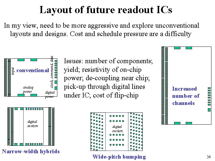
Layout of future readout ICs conventional analog power clock, command, data input In my view, need to be more aggressive and explore unconventional layouts and designs. Cost and schedule pressure a difficulty digital power digital section Narrow-width hybrids Issues: number of components; yield; resistivity of on-chip power; de-coupling near chip; pick-up through digital lines under IC; cost of flip-chip Increased number of channels digital section Wide-pitch bumping 34
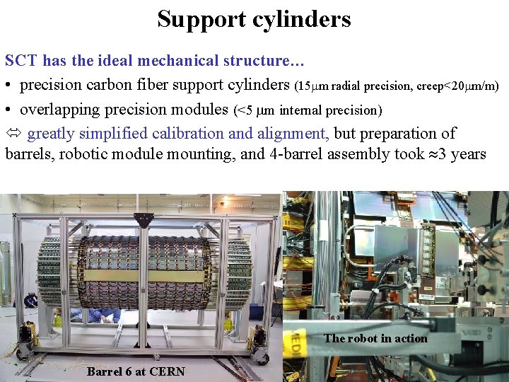
Support cylinders SCT has the ideal mechanical structure… • precision carbon fiber support cylinders (15 m radial precision, creep<20 m/m) • overlapping precision modules (<5 m internal precision) greatly simplified calibration and alignment, but preparation of barrels, robotic module mounting, and 4 -barrel assembly took 3 years The robot in action Barrel 6 at CERN 35
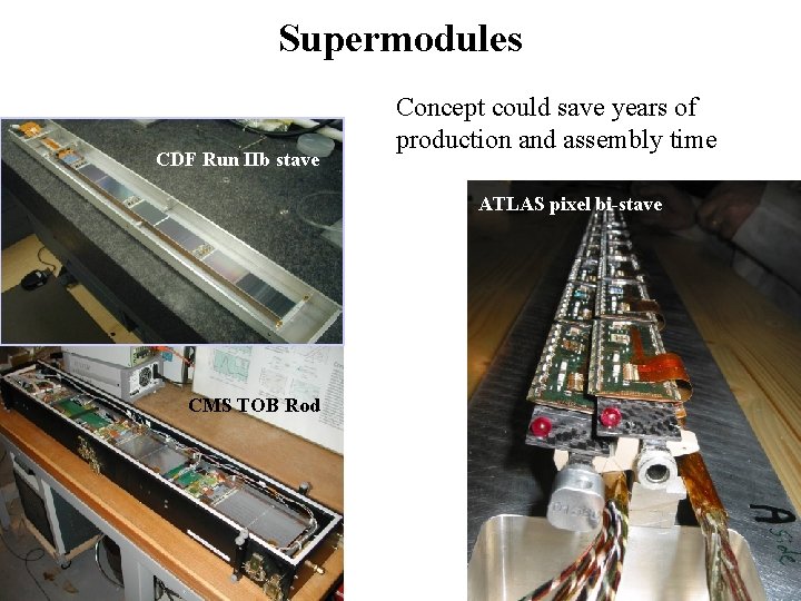
Supermodules CDF Run IIb stave Concept could save years of production and assembly time ATLAS pixel bi-stave The robot in action CMS TOB Rod 36
Supermodules on barrels? Can we combine the best of both approaches? • Rigidity and stability of low-mass CF cylinders • Integrated services, modularity, superior thermal performance, ease of assembly of supermodules Rationale: overhead in material is small. Courtesy N. Unno Lot’s of interest in ATLAS Courtesy D. Ferrere 37
Cooling and thermal management ATLAS silicon use C 3 F 8 evaporative cooling system. While this has not been without difficulties, evaporative cooling seems best for SLHC trackers • At LHC “mass-less designs” were pushed too hard and “plumbing” is a major concern (not only for ATLAS, not only for trackers) • Mass and reliability remain crucial at SLHC • Choice of coolant has severe implications. C 3 F 8 and CO 2 are main cooling candidates. • C 3 F 8 option hinges on low ΔT between coolant and sensor. CO 2 reaches lower temperatures, but operates at much higher pressures (see talk of Ann van Lysbetten) R&D on pipe materials, joining and welding techniques, highpressure testing has started. Trend to commercial solutions 38
The forward region • Forward region is more important at LHC than at previous hadron colliders. It’s certainly as important at (S)LHC as at ILC • Transition between central and forward region (traditionally barrel and disks) is challenging. This puzzle has not yet been solved. • Some features of forward regions – Obstruction by barrel services – Classical wedge shape requires different sensor types and is a nuisance (at least for strips) – On the other hand, less channels per volume So far we have focussed on generic R&D and the easier barrel… 39
Summary • Need detector upgrade to exploit LHC fully • Tracker upgrade is hardest and will drive silicon technology to unprecedented levels • It’s important to stay aggressive. Incremental improvements, while convenient, will not always suffice • Next few years of R&D will show if we can do it. At this stage it is looking good! 40
Appendix 41
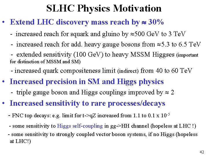
SLHC Physics Motivation • Extend LHC discovery mass reach by 30% - increased reach for squark and gluino by 500 Ge. V to 3 Te. V - increased reach for add. heavy gauge bosons from 5. 3 to 6. 5 Te. V - extended sensitivity (100 Ge. V) to heavy MSSM Higgses (important for distinction of MSSM and SM) - increased quark compositeness limit (indirect) from 40 to 60 Te. V • Increased precision in SM and Higgs physics - triple gauge boson and Higgs couplings improved by 2 • Increased sensitivity to rare processes/decays - FNC top decays: e. g. limit for t->q. Z increased from 1. 1 to 0. 1 x 10 -5 - some sensitivity to Higgs self-coupling in gg->HH channel (hopeless at LHC !) - some sensitivity to strongly coupled vector boson systems, if no Higgs (hopeless at LHC!) 42
43
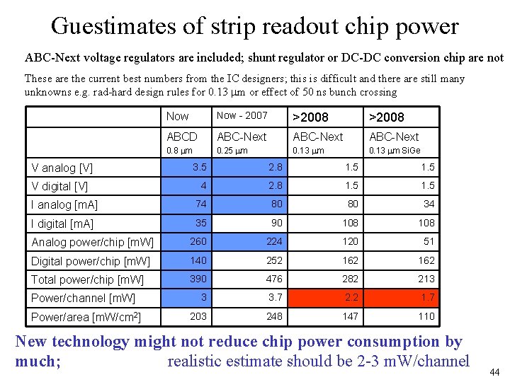
Guestimates of strip readout chip power ABC-Next voltage regulators are included; shunt regulator or DC-DC conversion chip are not These are the current best numbers from the IC designers; this is difficult and there are still many unknowns e. g. rad-hard design rules for 0. 13 m or effect of 50 ns bunch crossing Now - 2007 >2008 ABCD ABC-Next 0. 8 m 0. 25 m 0. 13 m Si. Ge 3. 5 2. 8 1. 5 4 2. 8 1. 5 I analog [m. A] 74 80 80 34 I digital [m. A] 35 90 108 Analog power/chip [m. W] 260 224 120 51 Digital power/chip [m. W] 140 252 162 Total power/chip [m. W] 390 476 282 213 3 3. 7 2. 2 1. 7 203 248 147 110 V analog [V] V digital [V] Power/channel [m. W] Power/area [m. W/cm 2] New technology might not reduce chip power consumption by much; realistic estimate should be 2 -3 m. W/channel 44