
Slender Structures Load carrying principles Basic systems Serial
Slender Structures Load carrying principles Basic systems: • Serial • Parallel v 2019 -1 Hans Welleman 1

Content (preliminary schedule) q Basic cases q q – Extension, shear, torsion, cable – Bending (Euler-Bernoulli) Combined systems - Parallel systems - Special system – Bending (Timoshenko) Continuously Elastic Supported (basic) Cases Cable revisit and Arches Matrix Method Hans Welleman 2
Learning objectives Extend the technique for basic models to systems n Find the ODE for a specific system and the boundary conditions for the specific application n Solve the more advanced ODE’s (by hand MAPLE) n Investigate consequences/limitations of the model and check results with limit cases n Hans Welleman 3
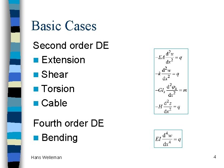
Basic Cases Second order DE n Extension n Shear n Torsion n Cable Fourth order DE n Bending Hans Welleman 4
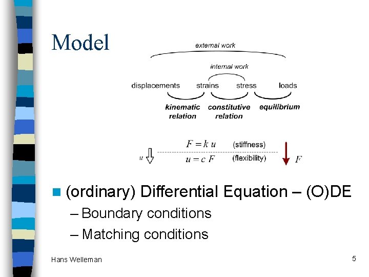
Model n (ordinary) Differential Equation – (O)DE – Boundary conditions – Matching conditions Hans Welleman 5
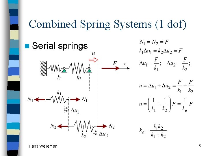
Combined Spring Systems (1 dof) n Serial Hans Welleman springs 6
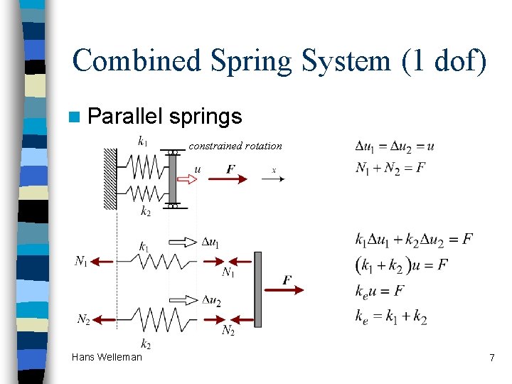
Combined Spring System (1 dof) n Parallel springs constrained rotation Hans Welleman 7
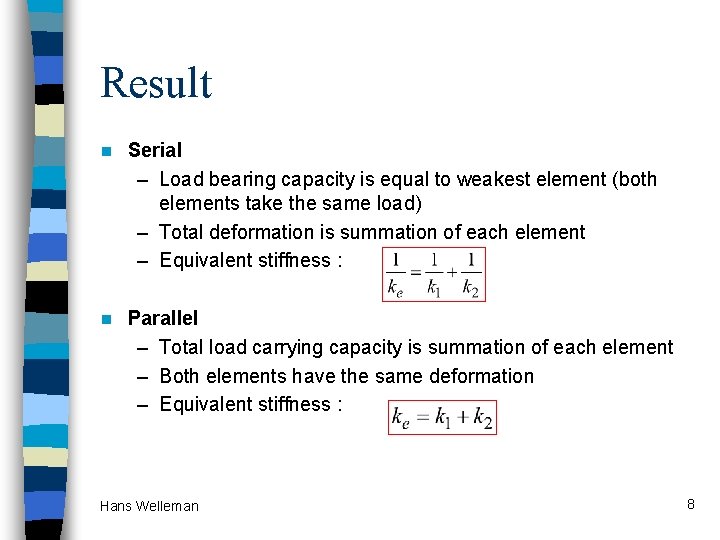
Result n Serial – Load bearing capacity is equal to weakest element (both elements take the same load) – Total deformation is summation of each element – Equivalent stiffness : n Parallel – Total load carrying capacity is summation of each element – Both elements have the same deformation – Equivalent stiffness : Hans Welleman 8
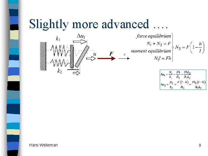
Slightly more advanced …. Hans Welleman 9
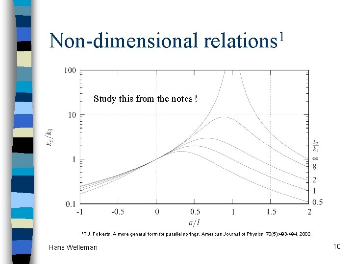
Non-dimensional 1 relations Study this from the notes ! 1 T. J. Folkerts, A more general form for parallel springs, American Journal of Physics, 70(5): 493 -494, 2002 Hans Welleman 10

Application neglect unloaded spring length b = spring length in deformed state n l = additional cables (no stress) n a = chord which will be cut n n What will happen to the block depending upon the values of a, b and l. Source : Johan Blaauwendraad, BD magazine 2, nov 1998. Hans Welleman 11
Combine basic cases n Parallel system – Bending and cable – Bending and shear n Special “serial” system – Bending and shear, Timoshenko Beam Hans Welleman 12

System with cable + bending + Same deflection, therefore P-system n Capacity is sum of elements n Hans Welleman 13
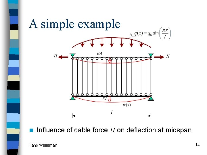
A simple example n Influence of cable force H on deflection at midspan Hans Welleman 14
General solution ? wh(x) = …………………… wp(x) = …………………… Hans Welleman 15
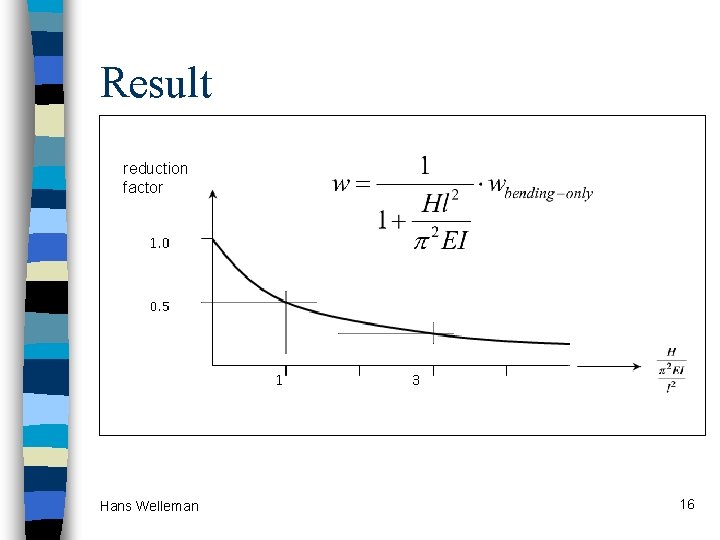
Result reduction factor n only bending Hans Welleman 16

Parallel system cable + bending Suspension Bridge Clifton Suspension Bridge (1864) crossing the Avon at Bristol. Designed by Isambard Kingdom Brunel [source: The Telegraph. co. uk] Hans Welleman 17
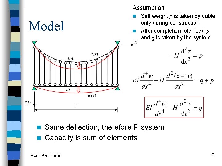
Assumption Model Self weight p is taken by cable only during construction n After completion total load p and q is taken by the system n Same deflection, therefore P-system n Capacity is sum of elements n Hans Welleman 18
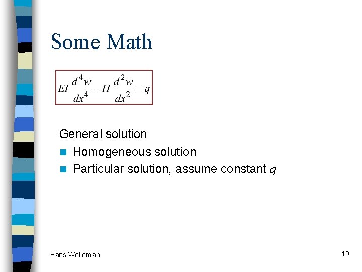
Some Math General solution n Homogeneous solution n Particular solution, assume constant q Hans Welleman 19
I found as an answer wh(x) = …………………… wp(x) = …………………… Hans Welleman 20
Examples 1 n Wheel load on cables with bending stiffness, n Constrained bending with tension, n Offshore risers, n High rise buildings 1 A. L. Bouma, Mechanica van Constructies, Elasto-static van slanke structuren, VSSD, ISBN 9789040712784, 2000 Hans Welleman 21
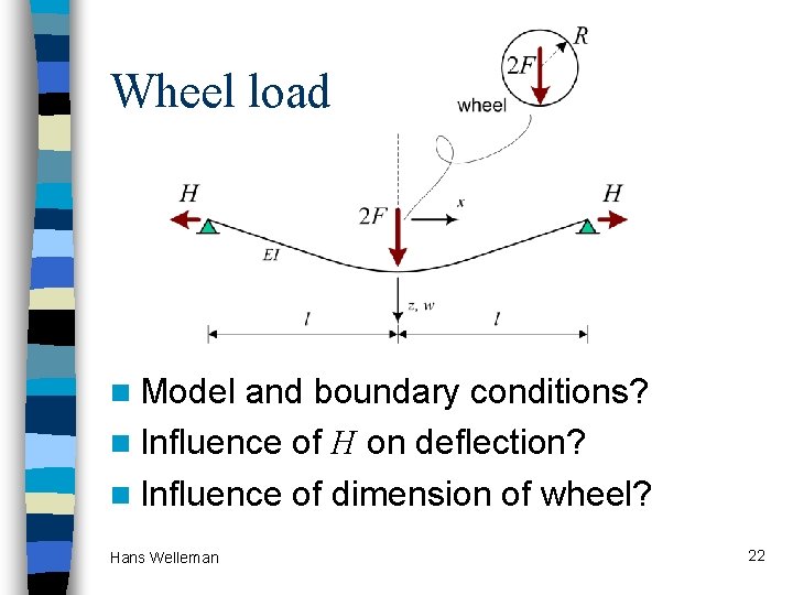
Wheel load n Model and boundary conditions? n Influence of H on deflection? n Influence of dimension of wheel? Hans Welleman 22
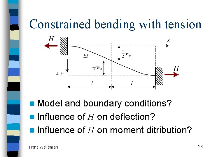
Constrained bending with tension n Model and boundary conditions? n Influence of H on deflection? n Influence of H on moment ditribution? Hans Welleman 23
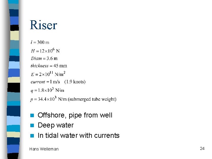
Riser Offshore, pipe from well n Deep water n In tidal water with currents n Hans Welleman 24
Model n Assume constant H n Define boundary conditions n Find deformed position h n What answer 6. 75 m if H is not constant … Let’s use MAPLE …. Hans Welleman 25
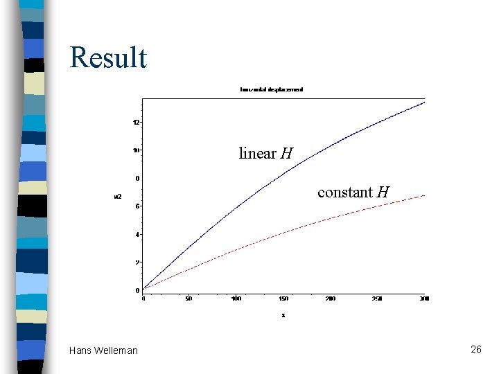
Result linear H constant H Hans Welleman 26
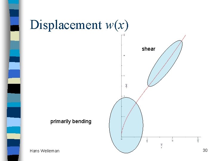
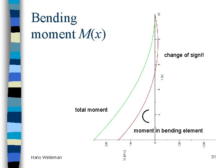
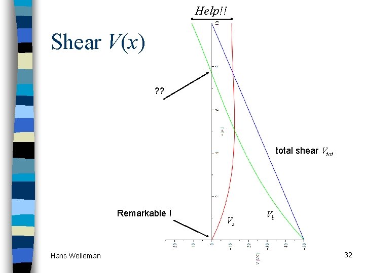
High Rise n Shear frame combined with bending element (elevator or staircase tower) Hans Welleman 27
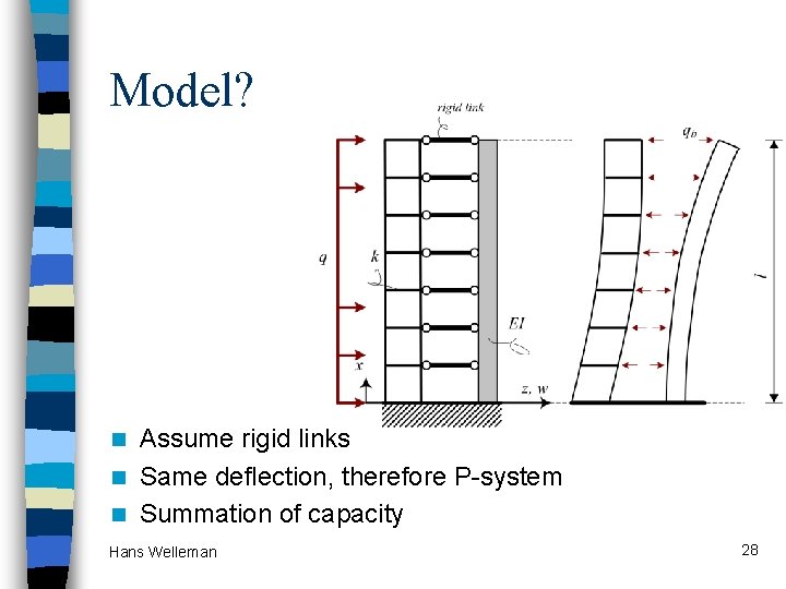
Model? Assume rigid links n Same deflection, therefore P-system n Summation of capacity n Hans Welleman 28
Solve this problem n ODE n Boundary Conditions n Solution and interpretation Let’s use MAPLE …. Hans Welleman 29
Displacement w(x) shear primarily bending Hans Welleman 30
Bending moment M(x) change of sign!! total moment in bending element Hans Welleman 31
Help!! Shear V(x) ? ? total shear Vtot Remarkable ! Hans Welleman Vs Vb 32
Results n Fight between shear and bending n Concentrated force in the top link n All shear load to foundation of the tower n Change of sign in moment distribution Hans Welleman 33
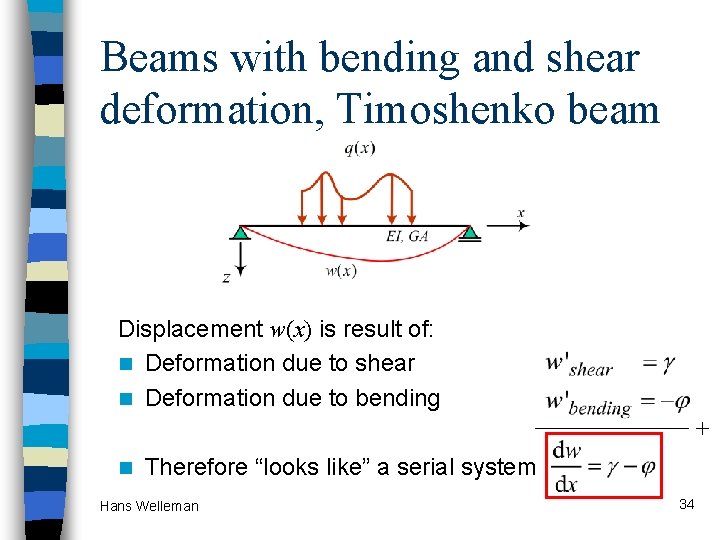
Beams with bending and shear deformation, Timoshenko beam Displacement w(x) is result of: n Deformation due to shear n Deformation due to bending + n Therefore “looks like” a serial system Hans Welleman 34
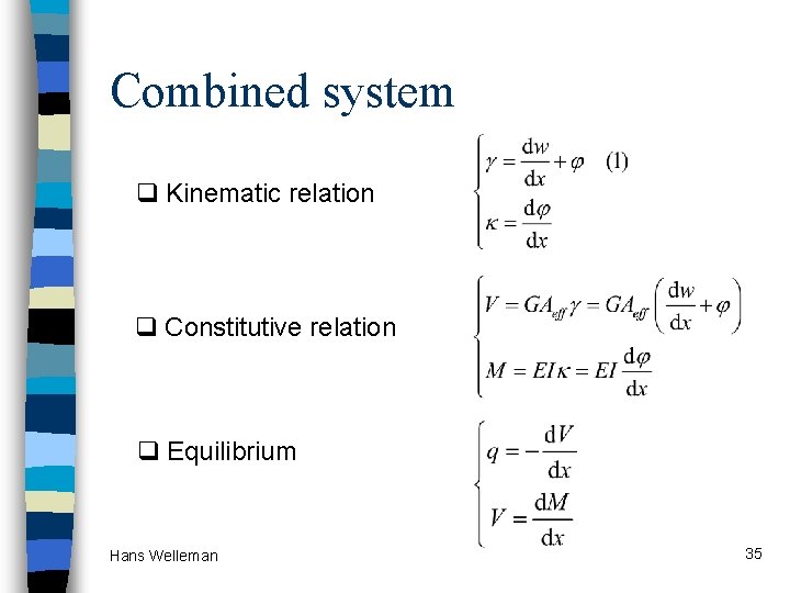
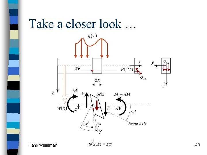
Combined system q Kinematic relation q Constitutive relation q Equilibrium Hans Welleman 35
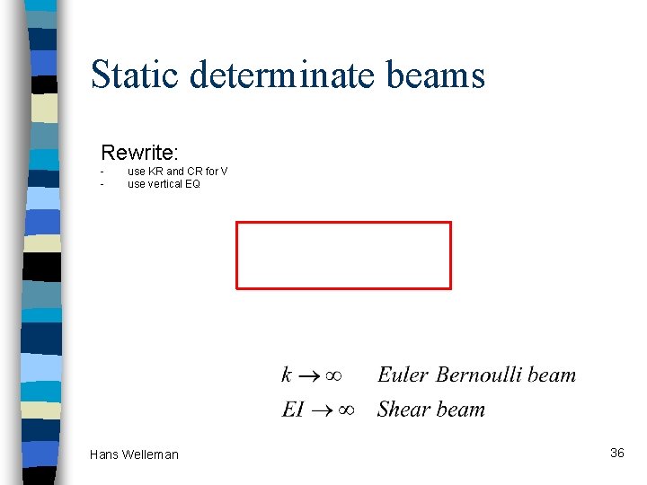
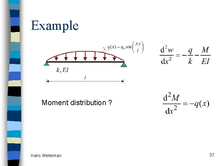
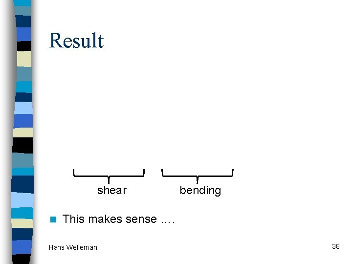
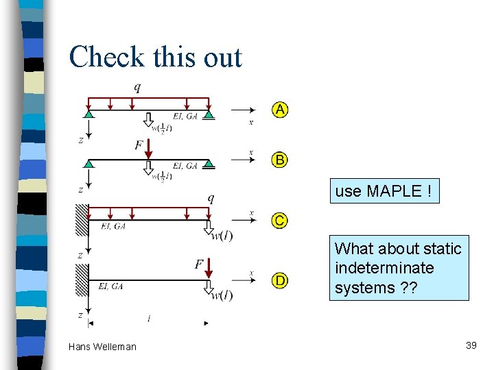
Static determinate beams Rewrite: - use KR and CR for V use vertical EQ Hans Welleman 36
Example Moment distribution ? Hans Welleman 37
Result shear n bending This makes sense …. Hans Welleman 38
Check this out use MAPLE ! What about static indeterminate systems ? ? Hans Welleman 39
Take a closer look … Hans Welleman 40
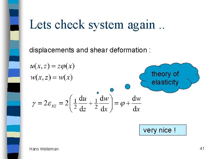
Lets check system again. . displacements and shear deformation : theory of elasticity very nice ! Hans Welleman 41
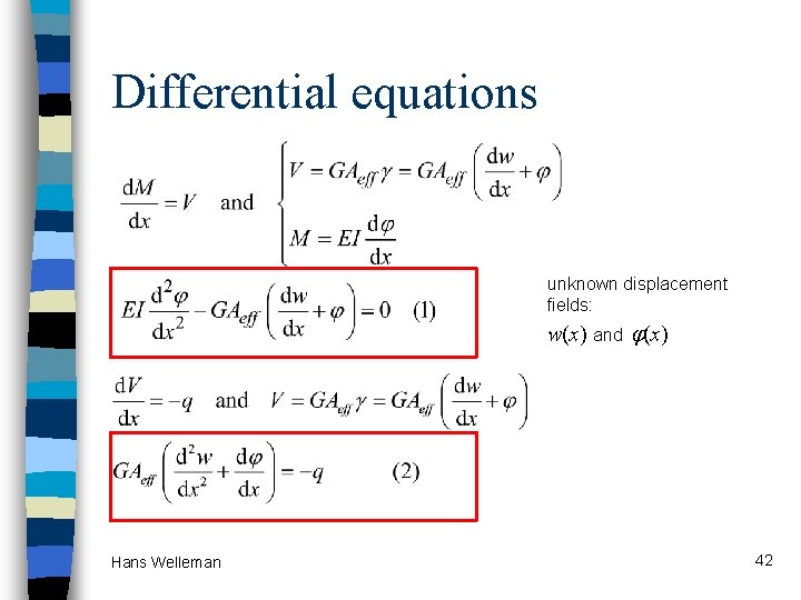
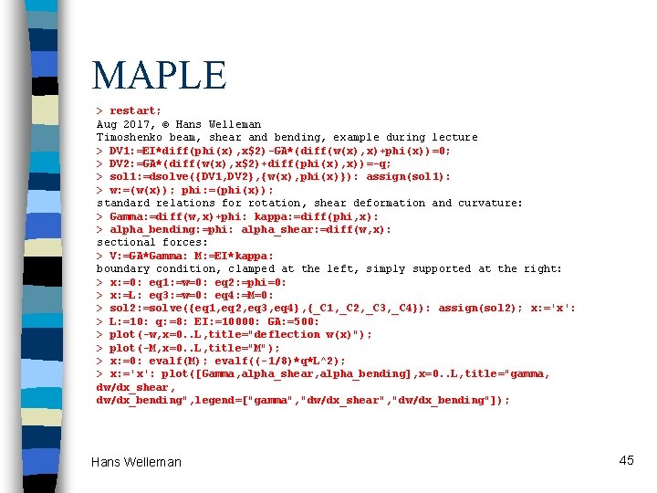
Differential equations unknown displacement fields: w(x) Hans Welleman and (x) 42
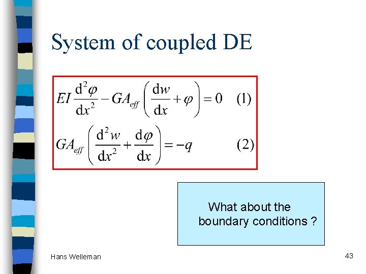
System of coupled DE What about the boundary conditions ? Hans Welleman 43
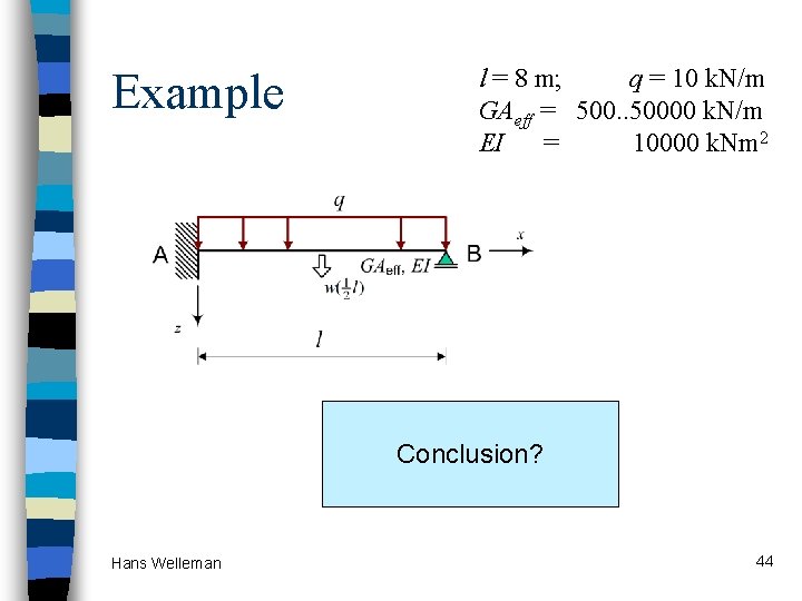
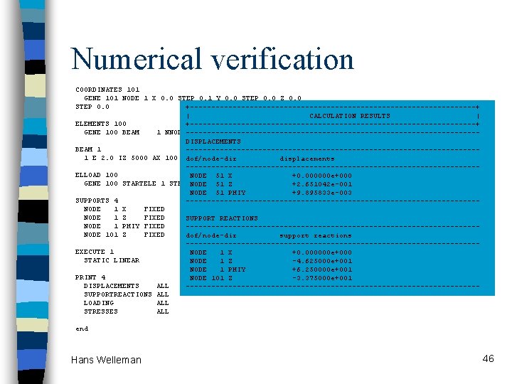
Example l = 8 m; q = 10 k. N/m GAeff = 500. . 50000 k. N/m EI = 10000 k. Nm 2 Conclusion? Hans Welleman 44
MAPLE > restart; Aug 2017, © Hans Welleman Timoshenko beam, shear and bending, example during lecture > DV 1: =EI*diff(phi(x), x$2)-GA*(diff(w(x), x)+phi(x))=0; > DV 2: =GA*(diff(w(x), x$2)+diff(phi(x), x))=-q; > sol 1: =dsolve({DV 1, DV 2}, {w(x), phi(x)}): assign(sol 1): > w: =(w(x)); phi: =(phi(x)); standard relations for rotation, shear deformation and curvature: > Gamma: =diff(w, x)+phi: kappa: =diff(phi, x): > alpha_bending: =phi: alpha_shear: =diff(w, x): sectional forces: > V: =GA*Gamma: M: =EI*kappa: boundary condition, clamped at the left, simply supported at the right: > x: =0: eq 1: =w=0: eq 2: =phi=0: > x: =L: eq 3: =w=0: eq 4: =M=0: > sol 2: =solve({eq 1, eq 2, eq 3, eq 4}, {_C 1, _C 2, _C 3, _C 4}): assign(sol 2); x: ='x': > L: =10: q: =8: EI: =10000: GA: =500: > plot(-w, x=0. . L, title="deflection w(x)"); > plot(-M, x=0. . L, title="M"); > x: =0: evalf(M); evalf((-1/8)*q*L^2); > x: ='x': plot([Gamma, alpha_shear, alpha_bending], x=0. . L, title="gamma, dw/dx_shear, dw/dx_bending", legend=["gamma", "dw/dx_shear", "dw/dx_bending"]); Hans Welleman 45
Numerical verification COORDINATES 101 GENE 101 NODE 1 X 0. 0 STEP 0. 1 Y 0. 0 STEP 0. 0 Z 0. 0 STEP 0. 0 +----------------------------------+ | CALCULATION RESULTS | ELEMENTS 100 +----------------------------------+ GENE 100 BEAM 1 NNODE----------------------------------2 1 STEP 1 2 STEP 1 DISPLACEMENTS BEAM 1 ----------------------------------1 E 2. 0 IZ 5000 AX 100 AY 500 rho 0 NU 0. 0 FREE dof/node-dir displacements ----------------------------------ELLOAD 100 NODE 51 X +0. 000000 e+000 GENE 100 STARTELE 1 STEP NODE 1 DIRE 51 YLZ FIXED Q 8 +2. 651042 e-001 NODE 51 PHIY +9. 895833 e-003 SUPPORTS 4 ----------------------------------NODE 1 X FIXED NODE 1 Z FIXED SUPPORT REACTIONS NODE 1 PHIY FIXED ----------------------------------NODE 101 Z FIXED dof/node-dir support reactions ----------------------------------EXECUTE 1 NODE 1 X +0. 000000 e+000 STATIC LINEAR NODE 1 Z -4. 625000 e+001 NODE 1 PHIY +6. 250000 e+001 PRINT 4 NODE 101 Z -3. 375000 e+001 DISPLACEMENTS ALL ----------------------------------SUPPORTREACTIONS ALL LOADING ALL STRESSES ALL end Hans Welleman 46
- Slides: 46