Skylight A Window on Shingled Disk Operation Abutalib

Skylight A Window on Shingled Disk Operation Abutalib Aghayev Peter Desnoyers Northeastern U.
 n")
Paper highlights n Discusses a new storage technology ¨ Shingled Magnetic Recording (SMR) n Describes the true on-disk organization of a SMR drive ¨ Hidden by the Shingle Translation Layer (STL) of the drive ¨ Required specific SW and HW measurement tools

Paper organization n Four parts: ¨ Overview of current state of Shingled Magnetic Recording (SMR) technology ¨ Simulating the Shingle Translation Layer (STL) of SMR disks ¨ Comparing with measurements of two actual SMR disks ¨ Conclusions Will focus this time on first and last parts of paper

Introduction n Magnetic disks are not dead! ¨ Over 400 exabytes of storage shipped in 2013 n Almost 60 GB for each person on earth ¨ Factor of ten advantage on flash n Total bits shipped n Cost by bit 1888: First magnetic audio recording 1956: First disk storage unit (IBM RAMAC)

Reason for this survival n Continuous increases in storage density: ¨ Perpendicular magnetic recording (PMR) n Bits as short as 20 nm in tracks 70 nm wide n Terabyte drives ¨ Shingled Magnetic Recording (SMR) n Radically new technology ¨Change the way data are written to disk n Already on the market: ¨ Now, 8 TB drives from Seagate

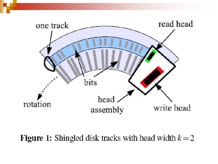
Shingled drives n n Space tracks more closely ¨ Overlap like rows of shingles on a roof ¨ More tracks per platter Price to pay ¨ Modifying a disk sector will corrupt data on the overlapped tracks n The "next" tracks ¨ Must copy them to avoid data loss

Conventional disk drives • Each track is directly accessible • Can be individually updated

SMR drives • Write head stretches over k tracks • Updating a single disk track will overwrite data on the next k -1 tracks Corrupted tracks

Consequences n Disks become append-only media n Not the way modern file systems interact with their storage devices

Disk organization n n Read head reads one track at a time Write head writes k tracks at a time ¨ One track will contain the data ¨ Remaining k -1 tracks will be reused later Read head Write head

Two options n n Modify the file system ¨ Moving to a log-structured file system ¨… Modify the disk firmware ¨ Maintain conventional interface to the OS ¨ Add a Shingle Translation Layer (STL) n Will use both out-of-place writes and dynamic mapping ¨ Just like flash drives do!

Pros and cons n Sole solution for rapid adoption of SMR drives ¨ Does not require modifying the host OS n But ¨ Adds complexity to the disk firmware ¨ Does not let the OS file system optimize its reads and writes for the actual on-disk data organization

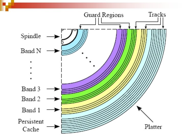
Storing data n n Simplest solution would be to treat each disk platter as a sequential log ¨ What to do when the disk is full n Cleanup will create cascading rewrites Best solution is to organize platters into bands of b tracks separated by k – 1 guard tracks that will remain unused ¨ Will only use b/(b + k – 1) fraction of the available disk space

Bands and guards Guard region Band 3 Guard region Band 1

Managing bands n n n Updating a track in a band requires rewriting all following tracks of the band Bands could be managed by the file system In reality, SMT disks ¨ Export a conventional disk interface ¨ Include a Shingle Translation Layer (STL) in the disk firmware n Similar to Flash Translation Layer (FTL) of flash drives

STL and FTL n Both perform writes using larger units: ¨ Bands and pages but SMT disks ¨ Have high times for non-sequential access ¨ Lack high-speed reads ¨ Use much larger cleaning units n Tens to hundreds of MB ¨ Do not need wear leveling.

The persistent cache n n Contains copies of recently accessed blocks Occupies a small portion of the disk Contents identified in a persistent cache map Cleaning, ¨ Moves back data from the cache to the bands ¨ Performs read-modify-write (RMW) on every band whose data was overwritten ¨ Can be n Lazy, only running when needed n Aggressive, running during idle times

Emulating STL of SMT drives n Will implement kernel modules emulating ¨ set-associative STL ¨ fully-associative STL both from Cassuto et al.

Set-associative STL n n n Partitions disk into ¨ N data bands of equal capacity (20 -40 Mi. B) ¨ One small persistent cache n One to 10 percent of disk capacity Persistent caches n << N full bands ¨ Band a can only occupy cache slot a mod n Cached bands are ¨ Updated in place (write-back policy) ¨ Expelled when cache is full
 Manages each")
Fully-associative STL n n Partitions disk into large zones (40 Gi. B) Manages each zone independently Zones start with 5 percent of capacity provisioned for free bands When a block in logical band a is to be written to the corresponding physical band b ¨ A free band c is chosen and written to ¨ The persistent cache map is updated

Fully-associative STL n When the number of free bands falls below a threshold, ¨ Cleaning merges the bands b and c ¨ Writes it to a new band d ¨ Remaps the logical band a to the physical band d ¨ Frees bands b and c

Fully-associative STL n n Dynamic mapping of bands allows STL to handle streaming writes with zero overhead Organizing disk into zones minimizes disk seeks during cleaning operations ¨ Can use aggressive cleaning

Before the update a b c FREE d FREE

After the update a b c UPDATED d FREE

After the cleaning a b FREE c FREE d

Emulation validity issues n Can we emulate a STL in software using a CMR disk whose exact sector layout we ignore? n YES, because the STL of SMR disks sits on the top of the layer that manages actual sector layout and bad block relocation

Emulated configurations n Two set associative configurations with ¨ Different persistent caches n 37. 2 GB on disk n 9. 98 GB of flash ¨ Different band sizes (25 and 40 MB)
 ¨ 5900")
The real drives n n n Seagate ST 5000 AS 0011 (Seagate-SMR) ¨ 5900 rpm 5 TB desktop drive ¨ Four platters and eight heads Seagate ST 8000 AS 0011 ¨ 5900 rpm 8 TB desktop drive ¨ Six platters and twelve heads Seagate ST 4000 NC 001 (Seagate-CMR) ¨ 4 TB CMR drive used for emulation ¨ Otherwise identical to Seagate ST 5000 AS 0011
 n n Can we differentiate between SMR and CMR disks? Does")
Characterization goals (I) n n Can we differentiate between SMR and CMR disks? Does the drive use on disk or flash persistent cache? If the cache is on disk is at a single location for distributed? Does the drive use lazy or aggressive cleaning? When and how will the persistent cache become full?
 n n n What the drive band sizes? Are they static")
Characterization goals (II) n n n What the drive band sizes? Are they static or evolving? Is the block mappings for non-cached blocks fixed or dynamic? If the disk has zones, how are they structured?
 n . Software part: ¨ Launch crafted I/O operations using fio. ¨")
Skylight (I) n . Software part: ¨ Launch crafted I/O operations using fio. ¨ Disable n kernel read-ahead n drive look-ahead n on-board volatile cache. ¨ Use latency to infer drive properties
 n . Hardware part: ¨ Install a transparent window on the drive.")
Skylight (II) n . Hardware part: ¨ Install a transparent window on the drive. ¨ Track head movements using a high-speed camera. ¨ Derive head position graphs

Discovering the drive type and the persistent cache type n n n Write blocks in the first 1 Gi. B in random order. If latency is fixed then ¨ The drive uses SMR n All writes go to permanent cache otherwise ¨ We have a CMR drive Sub-millisecond latency would indicate the presence of a persistent flash cache.

Measurements Very low flash latency Very high latency

Results n n n The two emulated and the true SMR drives exhibit flat latencies The CMR drive exhibits variable latencies ¨ No persistent cache on disk The Seagate SMR drive latencies are not compatible with the presence of a persistent flash cache ¨ The drive uses SMR and has a on-disk persistent cache

Discovering Disk Cache Location and Structure n Test exploits a phenomenon called “fragmented reads” ¨ Do a sequential read that accesses both cached and non cached blocks ¨ Do fragmented reads at different offsets to infer the persistent cache location based on seek times

Measurements

Results n n n Emulated-SMR-1 ¨ Average latency high at low offset n Cache at ID (highest LBA address) Seagate-SMR ¨ Average latency is high at high offset n Cache at OD (lowest block address) ● Emulated-SMR-3: ¨ Average latency is roughly fixed n Distributed cache

Discovering the band sizes n n n Test relies on the fact that cleaning proceeds at a band granularity. Choose a small region (~1 Gi. B) and write blocks in random order. Pause for three to five seconds, letting the cleaner clean a few bands. Sequentially read the blocks in the region. Most latencies will be random ¨ Streak of flat latencies will identify a band.

Measurements

Results n Emulated-SMR-1 band size is 40 Mi. B. n Emulated-SMR-2 band size is 25 Mi. B ¨ Cache reads are sub-ms due to persistent flash cache ¨ Emulated-SMR-3 band size is 20 Mi. B n Seagate-SMR band size is 36 Mi. B, becomes smaller towards the higher LBA addresses ¨ Along with number of sectors per track

Summary of results n Cache type and size: ¨ Both SMR drives use a persistent disk cache n 20 Gi. B on 5 TB drive n 25 Gi. B on 8 TB drive ¨ Provide high random write speeds until the cache is full ¨ Effective cache size depends on write size and queue depth

Investigation results Not discussed n Persistent cache structure: ¨ Written as journal entries with quantized sizes n Not considered in the academic literature on SMRs. n Block Mapping: ¨ Non-cached data are statically mapped ¨ Fixed assignment of logical block addresses (LBAs) to physical block addresses (PBAs), similar to that used in CMR drives

Investigation results n n Band sizes: ¨ Rather small of 15– 40 Mi. B ¨ Bands are "rewritten as a unit" Not discussed Cleaning mechanism: ¨ Aggressive cleaning during idle times ¨ Takes 0. 6– 1. 6 s per modified band.
- Slides: 46