SKF Bearing Designations SKF Bearing Designations The basic

SKF Bearing Designations

SKF Bearing Designations The basic designation identifies: • Product type • Standard design • Size The supplementary designation identifies: • Alternative design (variants) • Bearing components • Types of special bearings


Width and Diameter Variations

ISO Standards ISO International Organization for Standardization

Diameter Series

Relationship: Diameter and Width Series

Dimension Series
 Thrust bearing,")
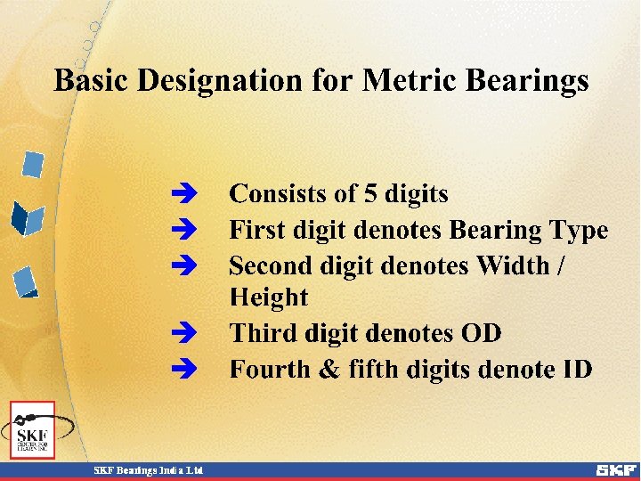
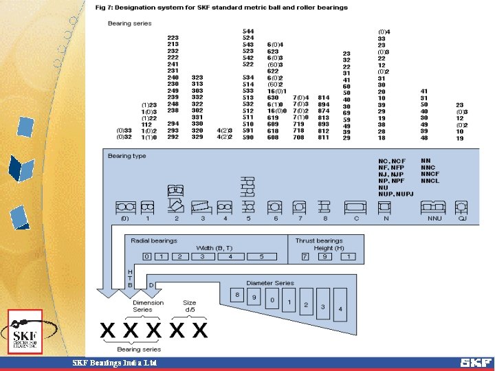
How the Designation System Works Bearing types Radial bearings, width (B, T) Thrust bearing, height (H) Outside diameter (D) Bearing size d/5 (30 mm bore diameter)

Bearing Type Designations: Cylindrical Roller Bearings NU NJ NUP N NU + HJ NJ + HJ

Basic Series Designations: Standard Inch Size Bearings L Bearing type L L Bearing series L Bore 1/8’s of inch

Standard Inch Size Bearing Types RLS RMS deep groove ball bearings RL RM self-aligning ball bearings ALS AMS angular contact ball bearings CRL CRM cylindrical roller bearings L: light series M: medium series

Example : Inch Size Designations RLS 10 deep groove ball, d = 1 1/4˝, light RL 16 self-aligning ball, d = 2˝, light ALS 40 angular contact ball, d = 5˝, light CRM 24 cylindrical roller, d = 3˝, medium O 20 thrust ball, d = 2 1/2˝

Inch Size Taper Roller Bearings: Cups and Cones Inch taper roller bearings are designed around roller & cage assemblies, and belong to families : Basic design (family)

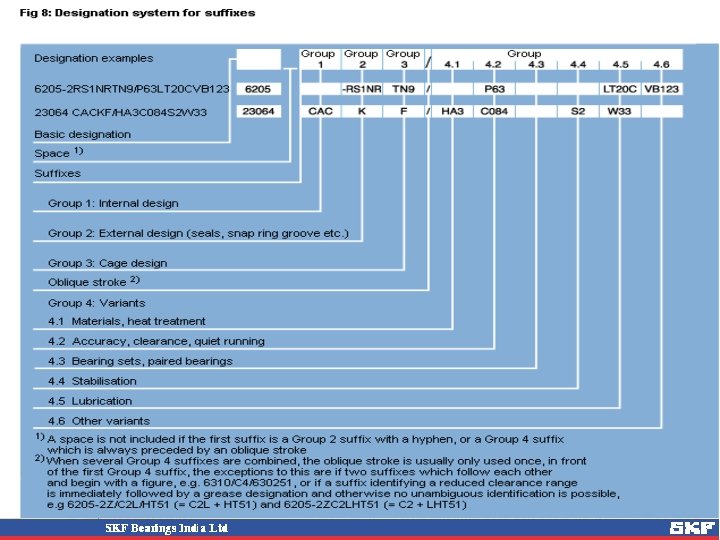
SKF Bearing Designations The supplementary designation identifies: • Variants – deviations from standard design • Grouped into four categories • Added to basic designation in a specific order, where more than one deviation applies

Categories of Supplementary Designations Category 1 : Modified Internal Design Category 2 : Modified External Design Category 3 : Modified Cage Design Category 4 : Modifications to enhance Performance

Category 1: Modified Internal Design A AC B BE C and combinations thereof such as CA/CB/CC CAC D E EC

Category 1: Modified Internal Design A : * Transitional Designation / changed after a period e. g. , 4210 A : DRDGBB without filling slot * Contact Angle 300 in SRACBB e. g. , 7056 A B : * Contact Angle 400 in SRACBB e. g. , 7210 B * Steep Contact Angle in TRB e. g. , 32210 B

Category 1: Modified Internal Design C : * Contact Angle 150 in SRACBB e. g. , 7012 C * SRB with loose Guide Flange , symmetrical rollers and pressed steel cage of window design AC : * Contact Angle 250 in SRACBB e. g. , 7210 AC D : * DRACBB with two part Inner Ring and Contact Angle of 450

Category 1: Modified Internal Design E : * Larger ball or Roller diameter e. g. , 29320 E CA : * SRB with loose guide ring but two integral flanges with machined brass cage e. g. , 23180 CA/W 33 * ACBB for universal mounting with low axial clearance when mounted in pair CAC : * SRB of CA design but with improved roller guidence

Category 1: Modified Internal Design CB : * ACBB for universal mounting with axial clearance larger than CA when mounted in pair CC : * ACBB for universal mounting with axial clearance larger than CB when mounted in pair * SRB of C design but with improved roller guidance EC : * Single Row CRB with a greater number of larger rollers than the original design, and increased axial load carrying capacity in Flanged executions e. g. , NU 320 EC / NJ 320 EC

Category 1: Modified Internal Design GA : * ACBB for universal mounting with light preload when mounted in pair GB : * ACBB for universal mounting with axial preload larger than GA when mounted in pair GC : * ACBB for universal mounting with axial preload larger than GB when mounted in pair

Category 2: Modified External Design K K 30 N N 1 N 2 N 4 N 6 NR : : : * * * Tapered Bore ( Taper 1 : 12 ) Tapered Bore ( Taper 1 : 30 ) Snap ring groove on bearing outer diameter One locating slot on outside edge of outer ring Two diametrically opposite locating slots on outside edge of outer ring : * N + N 2. Locating slots on side opposite to snap ring groove : * N + N 2. Locating slots on same side as snap ring groove : * Snap ring groove on bearing outer diameter along with an appropriate snap ring

Category 2: Modified External Design Tapered Bore Suffixes Suffix K Taper 1: 12 Suffix K 30 Taper 1: 30

Category 2: Modified External Design P PR : * SRB with two part outer ring, with calibrated spacer in between R : * Integral flange on outer ring outer diameter - RS : * NRB fitted with synthetic rubber seal on one side - 2 RS : * NRB fitted with synthetic rubber seals on two sides - RS 1 : * Rubbing seal of synthetic rubber with sheet steel reinforcement fitted on one side - 2 RS 1 : * Rubbing seal of synthetic rubber with sheet steel reinforcement fitted on both sides

Category 2: Modified External Design -RS 2 : * Rubbing seal consisting of sheet steel washer with vulcanized rubber fitted on one side - 2 RS 1 : * Rubbing seal consisting of sheet steel washer with vulcanized rubber fitted on both sides -RZ : * Ball bearing with low friction seal consisting of sheet steel washer with vulcanized rubber fitted on one side -2 RZ : * Ball bearing with low friction seal consisting of sheet steel washer with vulcanized rubber fitted on both sides

Category 2: Modified External Design X : * One or more of bearing external dimensions altered to fully comply with ISO standards -Z : * Metallic non-rubbing seal fitted on one side - 2 Z : * Metallic non-rubbing seal fitted on both sides

Suffixes: Seals and Shields Z 2 Z RZ 2 RZ RS 1 2 RS 1 N NR

Category 3: Modified Cage Design F FA FB FE H J JA JE L LA LB : : : * * * Machined Steel or SG Iron cage F Cage centred on outer ring F Cage centred on inner ring Machined Steel Cage phosphated Pressed cage of hardened sheet steel Pressed cage of unhardened sheet steel J Cage centred on outer ring J Cage phosphated Machined light alloy cage L Cage centred on outer ring L Cage centred on inner ring

Category 3: Modified Cage Design Cage Types

Category 3: Modified Cage Design M MA MB MP P TN Y V : : : * * * Machined Brass cage M Cage centred on outer ring M Cage centred on inner ring M Cage window type Moulded cage made of glass fibre reinforced polyamide 6. 6 : * Moulded cage made of plastic : * Pressed Brass cage : * Full complement bearing ( without cage )

Category 4: Modifications to enhance Performance /CL 7 A : * Standard SKF quality for Pinion Bearings /CL 7 C : * Special SKF quality for Pinion Bearings /CN : * Normal internal clearance. This usually used followed by H/M/L/P to denote part or displaced range e. g. : CNH : * Upper half of Normal CNM : * Two middle quarters of Normal CNL : * Lower half of Normal CNP : * Upper half of Normal & Lower half of C 3

Category 4: Modifications to enhance Performance /C 1 /C 2 /C 3 /C 4 /C 5 : : : * * * Internal clearance less than C 2 Internal clearance less than Normal Internal clearance more than C 3 Internal clearance more than C 4 A letter H/M/L/P following the clearance designation denotes part or displaced range. /C 01 /C 02 : * Reduced tolerance for running accuracy of I/R : * Extra reduced tolerance for running accuracy of I/R : less than C 01

Category 4: Modifications to Enhance Performance Suffix Range for Internal Clearances Radial internal clearance C 1 clearance less than C 2 clearance less than Normal C 3 clearance greater than Normal C 4 clearance greater than C 3 C 5 clearance greater than C 4 Axial internal clearance

Category 4: Modifications to enhance Performance /C 03 /C 04 : * Reduced tolerance for running accuracy of O/R : * Extra reduced tolerance for running accuracy of O/R : less than C 03 /C 05 /C 06 : : /C 10 : * Reduced tolerance for bore & OD. In case of tapered bore, refers to only OD. : * Bore diameter tolerance less than C 10 /C 20 * * C 01 + C 03 C 02 + C 03 C 01 + C 04 C 02 + C 04

Category 4: Modifications to enhance Performance /C 30 /C 40 /C 50 : * Reduced bore diameter tolerance, towards standard minimum limit. : * OD tolerance less than C 10 : * Reduced OD tolerance, towards standard minimum limit. /C 60 /C 70 /C 80 : * C 20 + C 50 : * C 20 + C 40 : * Reduced height tolerance for thrust bearings /C 15 /C 18 /C 78 : * C 10 + C 05 : * C 10 + C 08 : * C 70 + C 08

Category 4: Modifications to enhance Performance /DB /DF /DT /HA : * Two single row DGBB/ACBB/TRB, paired for mounting in back-to-back arrangement. : * Two single row DGBB/ACBB/TRB, paired for mounting in face-to-face arrangement. : * Two single row DGBB/ACBB/TRB, paired for mounting in tandem : * Case hardened bearing or bearing components. For closer identification, it is followed by one of following numbers : 0/1/2/3/4/5/6/7 e. g. , 1 Both rings 2 Outer ring 5 Rolling elements etc.

Category 4: Modifications to enhance Performance /HT : * Bearing supplied with High Temperature ( upto +1300 C) grease /LHT : * Bearing supplied with Low as well as High Temperature ( -40 to +1400 C) grease /LT : * Bearing supplied with Low Temperature ( upto -500 C) grease /MT : * Bearing supplied with Medium Temperature ( -30 to +1100 C) grease

Category 4: Modifications to enhance Performance /P 4 : * Dimensional and running accuracy to ISO tolerance class 4. /P 4 A : * Dimensional accuracy to ISO tolerance class 4 and running accuracy to AFBMA class 9. /P 5 : * Dimensional and running accuracy to ISO tolerance class 5 ( More accurate than P 6). /P 6 : * Dimensional and running accuracy to ISO tolerance class 6. /P 43 : * P 4 + C 3 /P 52 : * P 5 + C 2 /P 62 : * P 6 + C 2 /PA 9 : * Dimensional and running accuracy to AFBMA class 9.

Category 4: Modifications to enhance Performance /SP /S 0 /S 1 /S 2 /S 3 /S 4 : * Special Precision, dimensional accuracy approx. corresponding to P 5 and running accuracy approx. to P 4 : * Bearing dimensionally stabilized to optg. temperatures upto + 1500 C : * Bearing dimensionally stabilized to optg. temperatures upto + 2000 C : * Bearing dimensionally stabilized to optg. temperatures upto + 2500 C : * Bearing dimensionally stabilized to optg. temperatures upto + 3000 C : * Bearing dimensionally stabilized to optg. temperatures upto + 3500 C

Category 4: Modifications to enhance Performance /UP : * Ultra Precision, dimensional accuracy approx. corresponding to P 4 and running accuracy better than P 4 /W 20 : * Three lubrication holes in outer ring /W 33 : * Lubricating groove and three lubrication holes in outer ring /Vxxxx: * V plus a second letter followed by a three figure number denoting variants not covered by “logical” supplementary designations. e. g: VA 201 : Bearings for Kiln Trucks VA 301 : Bearings for Traction Motors

Category 4: Modifications to Enhance Performance Tolerance ISO Tolerance ABEC Tolerance SKF Tolerance RHP / NSK P 0 1 Normal P 0 P 6 3 P 6 P 5 5 P 5 P 4 7 SP P 4 A P 4 P 2 9 UP PA 9 A P 2

SKF Bearing Designations The sequence of writing the designations: • Prefix – if any • Basic designation • Supplementary designation of category 1 • Supplementary designation of category 2 • Supplementary designation of category 3 • Stroke • Supplementary designation of category 4

SKF Bearing Designations

SKF Bearing Designations The sequence of writing the designations: • Where two suffixes follow one another, the first ending with a figure and the second starting with one, a stroke is to be used e. g: 6310 / C 4/ 630251 • Where a suffix for a divided clearence range is followed by a suffix for type of grease, a stroke is to be used e. g : 6205 -2 Z/C 2 L/HT 51 (C 2 L + HT 51) but : 6205 -2 Z/C 2 LHT 51 (C 2 + LHT 51)

Date Codes The Year Letter to be marked on a bearing or a bearing accessory shall comprise a single letter in accordance with the table below Letter Year Year A B C 1910 1911 1912 1934 1935 1936 1958 1959 1960 1981 1982 1983 N O P 1922 1923 1924 1946 1947 1948 1970 1971 1972 1993 1994 1995 D E F 1913 1914 1915 1937 1938 1939 1961 1962 1963 1984 1985 1986 R S T 1925 1926 1927 1949 1950 1951 1973 1974 1975 1996 1997 1998 G E J 1916 1917 1918 1940 1941 1942 1964 1965 1966 1987 1988 1989 U V W 1928 1929 1930 1952 1953 1954 1976 – 1977 1999 – 2000 K L M 1919 1920 1921 1943 1944 1945 1967 1968 1969 1990 1991 1992 X Y Z 1931 1932 1933 1955 1956 1957 1978 1979 1980 2001 2002 2003
- Slides: 52