
SKA Pre Construction Phase Infrastructure Tracy Cheetham Carel


- Slides: 43
SKA Pre Construction Phase Infrastructure Tracy Cheetham Carel van der Merwe General Manager: Infra & Site Ops tcheetham@ska. ac. za Infrastructure System Engineer carel@ska. ac. za Michelle Storey Rebecca Wheadon CSIRO SKA Executive Officer michelle. storey@csiro. au Project Manager rebecca. wheadon@aurecongroup. com
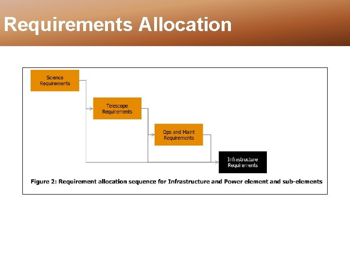
Requirements Allocation
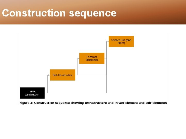
Construction sequence
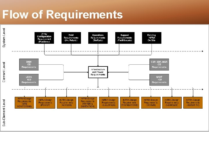
Flow of Requirements
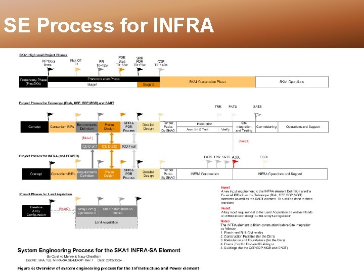
SE Process for INFRA
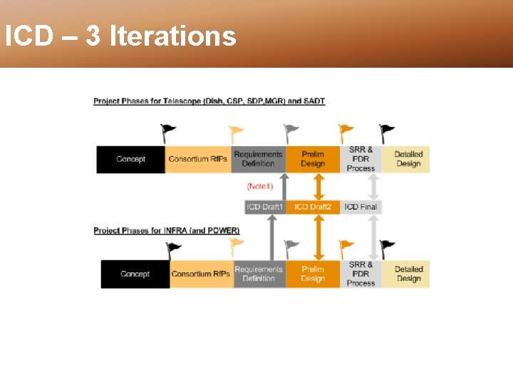
ICD – 3 Iterations
ICD – 3 Iterations • Iteration 1 (DRAFT 1) – Part of Requirement Definition (by RR) – Concept Driving IF requirements • Iteration 2 (DRAFT 2) – Agreed ICD between INFRA and other elements – Part of Preliminary Design (Part of PDR pack) • Iteration 3 (FINAL) – Signed Off at conclusion of PDR process – Formal change control for detailed design
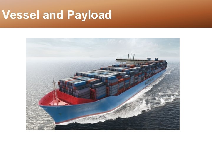
Vessel and Payload
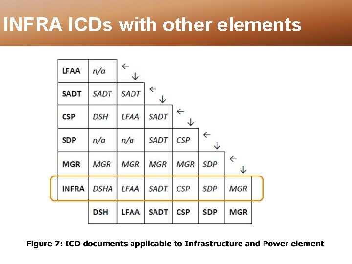
INFRA ICDs with other elements
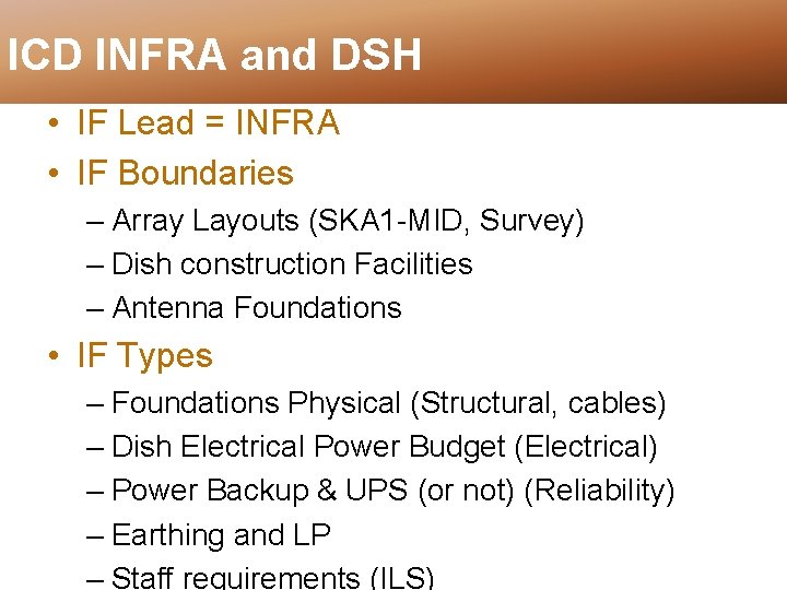
ICD INFRA and DSH • IF Lead = INFRA • IF Boundaries – Array Layouts (SKA 1 -MID, Survey) – Dish construction Facilities – Antenna Foundations • IF Types – Foundations Physical (Structural, cables) – Dish Electrical Power Budget (Electrical) – Power Backup & UPS (or not) (Reliability) – Earthing and LP – Staff requirements (ILS)
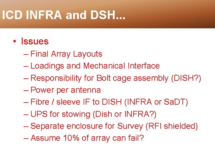
ICD INFRA and DSH. . . • Issues – Final Array Layouts – Loadings and Mechanical Interface – Responsibility for Bolt cage assembly (DISH? ) – Power per antenna – Fibre / sleeve IF to DISH (INFRA or Sa. DT) – UPS for stowing (Dish or INFRA? ) – Separate enclosure for Survey (RFI shielded) – Assume 10% of array can fail?
Dish - Bilateral • ICD lead =
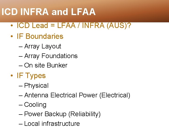
ICD INFRA and LFAA • ICD Lead = LFAA / INFRA (AUS)? • IF Boundaries – Array Layout – Array Foundations – On site Bunker • IF Types – Physical – Antenna Electrical Power (Electrical) – Cooling – Power Backup (Reliability) – Local infrastructure
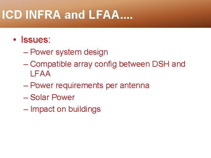
ICD INFRA and LFAA. . • Issues: – Power system design – Compatible array config between DSH and LFAA – Power requirements per antenna – Solar Power – Impact on buildings
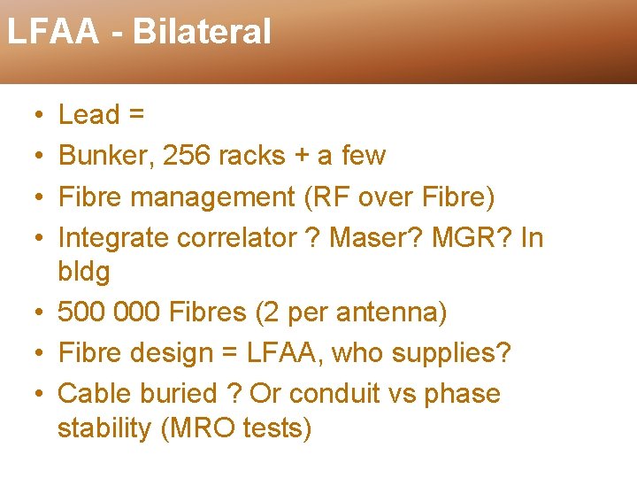
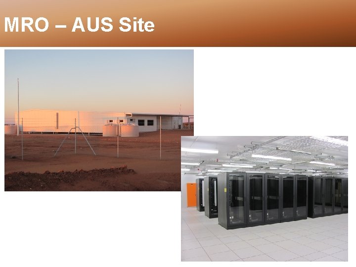
LFAA - Bilateral • • Lead = Bunker, 256 racks + a few Fibre management (RF over Fibre) Integrate correlator ? Maser? MGR? In bldg • 500 000 Fibres (2 per antenna) • Fibre design = LFAA, who supplies? • Cable buried ? Or conduit vs phase stability (MRO tests)
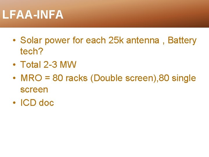
LFAA-INFA • Solar power for each 25 k antenna , Battery tech? • Total 2 -3 MW • MRO = 80 racks (Double screen), 80 single screen • ICD doc
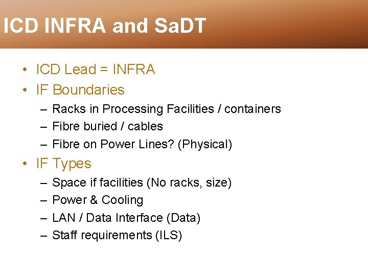
ICD INFRA and Sa. DT • ICD Lead = INFRA • IF Boundaries – Racks in Processing Facilities / containers – Fibre buried / cables – Fibre on Power Lines? (Physical) • IF Types – – Space if facilities (No racks, size) Power & Cooling LAN / Data Interface (Data) Staff requirements (ILS)
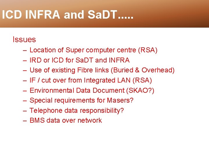
ICD INFRA and Sa. DT. . . Issues – – – – Location of Super computer centre (RSA) IRD or ICD for Sa. DT and INFRA Use of existing Fibre links (Buried & Overhead) IF / cut over from Integrated LAN (RSA) Environmental Data Document (SKAO? ) Special requirements for Masers? Telephone data responsibility? BMS data over network
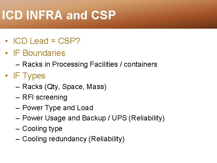
ICD INFRA and CSP • ICD Lead = CSP? • IF Boundaries – Racks in Processing Facilities / containers • IF Types – – – Racks (Qty, Space, Mass) RFI screening Power Type and Load Power Usage and Backup / UPS (Reliability) Cooling type Cooling redundancy (Reliability)
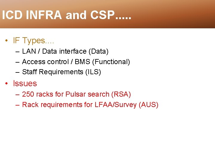
ICD INFRA and CSP. . . • IF Types. . – LAN / Data interface (Data) – Access control / BMS (Functional) – Staff Requirements (ILS) • Issues – 250 racks for Pulsar search (RSA) – Rack requirements for LFAA/Survey (AUS)
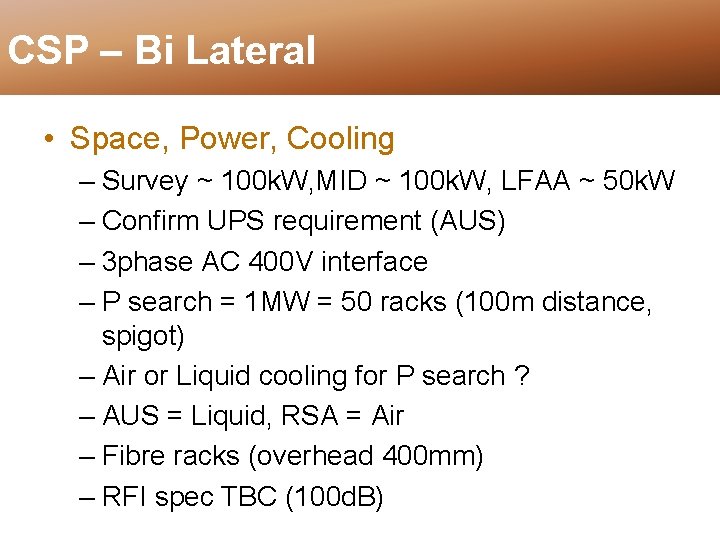
CSP – Bi Lateral • Space, Power, Cooling – Survey ~ 100 k. W, MID ~ 100 k. W, LFAA ~ 50 k. W – Confirm UPS requirement (AUS) – 3 phase AC 400 V interface – P search = 1 MW = 50 racks (100 m distance, spigot) – Air or Liquid cooling for P search ? – AUS = Liquid, RSA = Air – Fibre racks (overhead 400 mm) – RFI spec TBC (100 d. B)
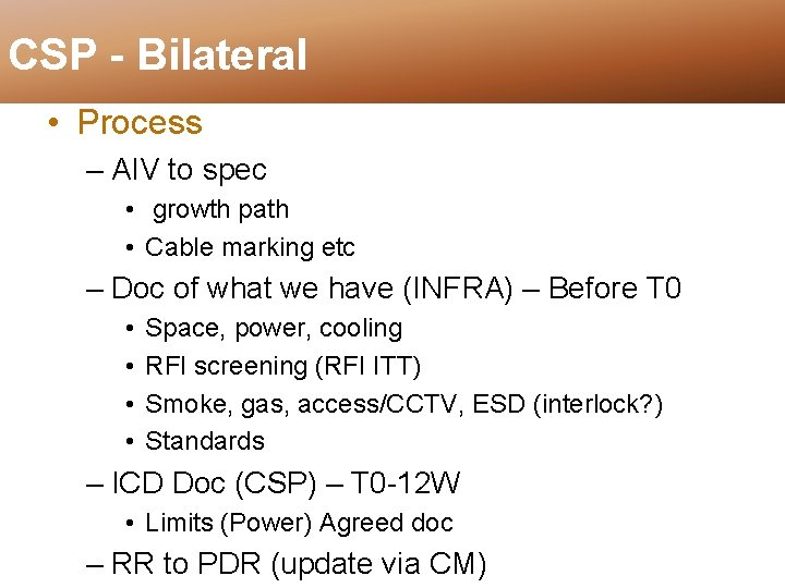
CSP - Bilateral • Process – AIV to spec • growth path • Cable marking etc – Doc of what we have (INFRA) – Before T 0 • • Space, power, cooling RFI screening (RFI ITT) Smoke, gas, access/CCTV, ESD (interlock? ) Standards – ICD Doc (CSP) – T 0 -12 W • Limits (Power) Agreed doc – RR to PDR (update via CM)
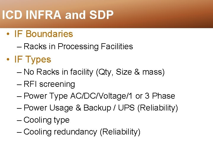
ICD INFRA and SDP • IF Boundaries – Racks in Processing Facilities • IF Types – No Racks in facility (Qty, Size & mass) – RFI screening – Power Type AC/DC/Voltage/1 or 3 Phase – Power Usage & Backup / UPS (Reliability) – Cooling type – Cooling redundancy (Reliability)
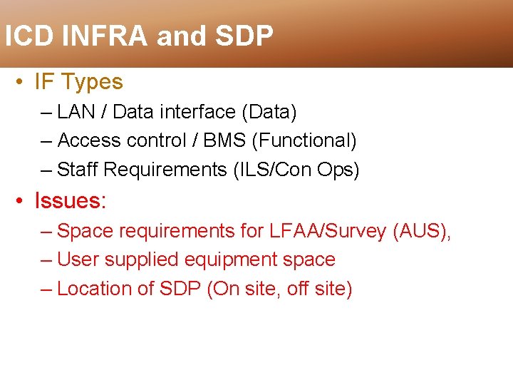
ICD INFRA and SDP • IF Types – LAN / Data interface (Data) – Access control / BMS (Functional) – Staff Requirements (ILS/Con Ops) • Issues: – Space requirements for LFAA/Survey (AUS), – User supplied equipment space – Location of SDP (On site, off site)
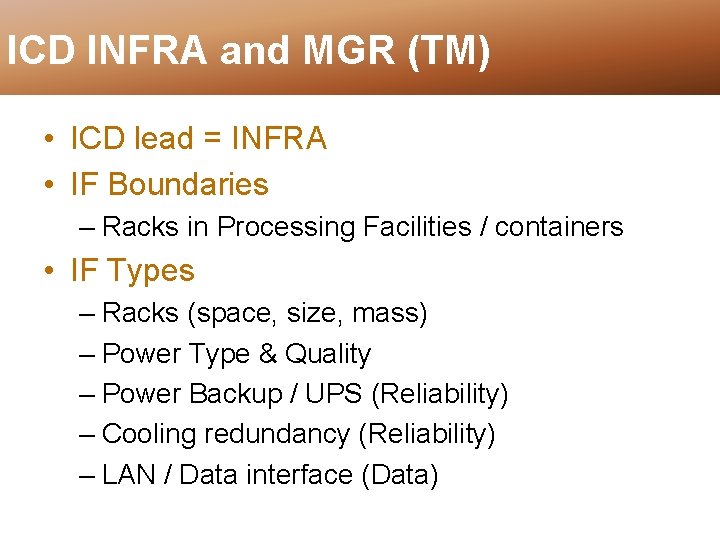
ICD INFRA and MGR (TM) • ICD lead = INFRA • IF Boundaries – Racks in Processing Facilities / containers • IF Types – Racks (space, size, mass) – Power Type & Quality – Power Backup / UPS (Reliability) – Cooling redundancy (Reliability) – LAN / Data interface (Data)
ICD INFRA and MGR. . . • IF Types. . . – Access control / BMS (Functional) – Staff Requirements (ILS) • Issues
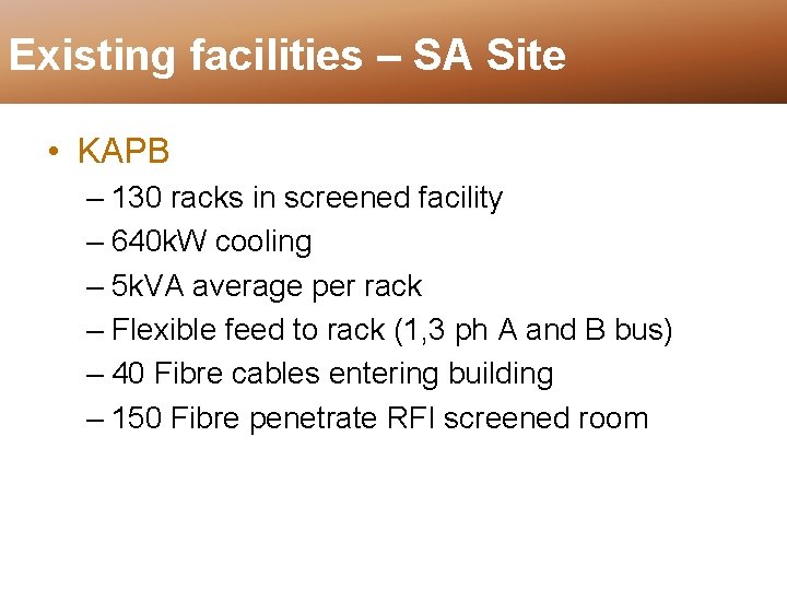
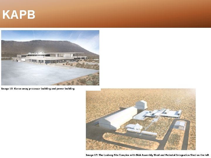
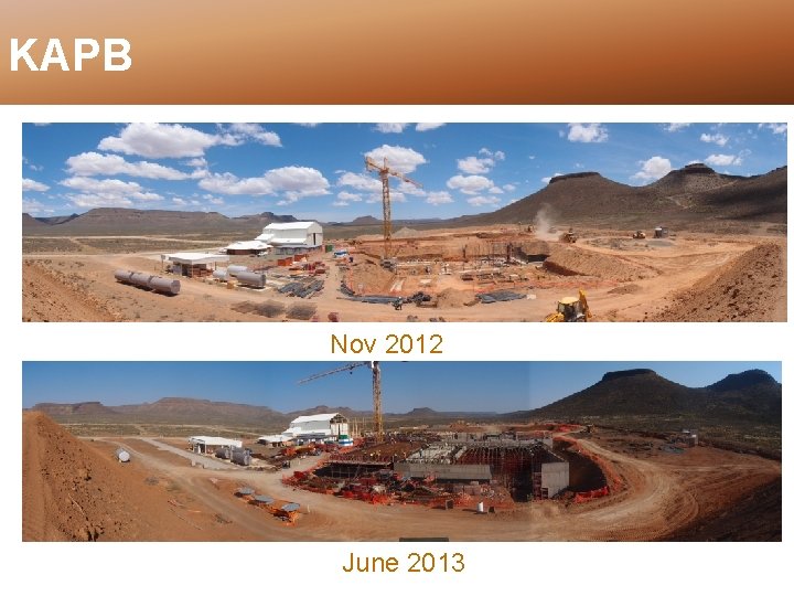
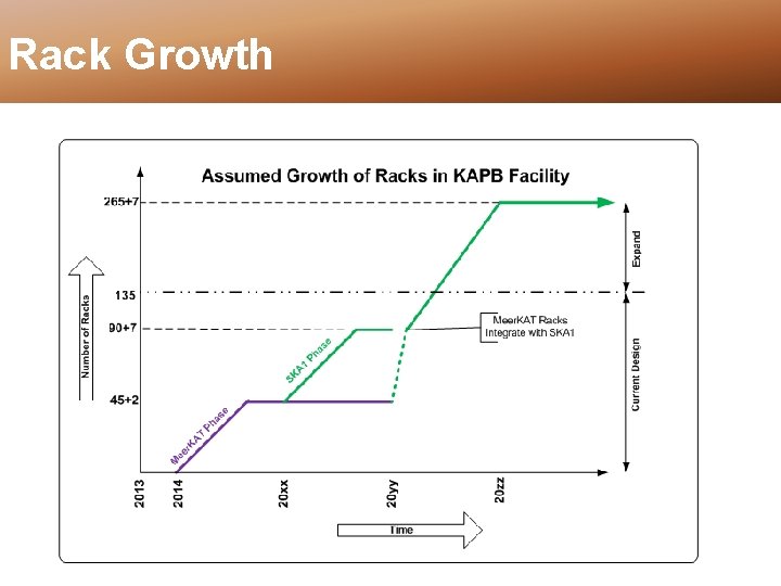
Existing facilities – SA Site • KAPB – 130 racks in screened facility – 640 k. W cooling – 5 k. VA average per rack – Flexible feed to rack (1, 3 ph A and B bus) – 40 Fibre cables entering building – 150 Fibre penetrate RFI screened room
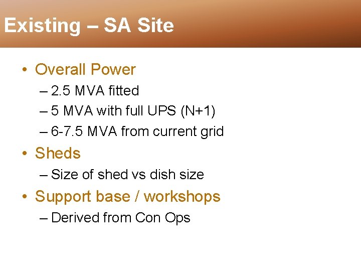
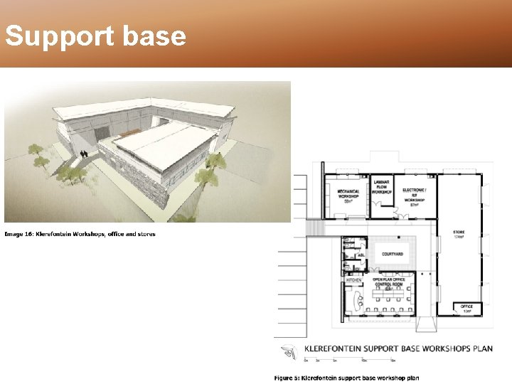
Existing – SA Site • Overall Power – 2. 5 MVA fitted – 5 MVA with full UPS (N+1) – 6 -7. 5 MVA from current grid • Sheds – Size of shed vs dish size • Support base / workshops – Derived from Con Ops
KAPB
KAPB Nov 2012 June 2013
KAPB Rack Layout
Rack Growth
Limitation – Grid Power
Support base
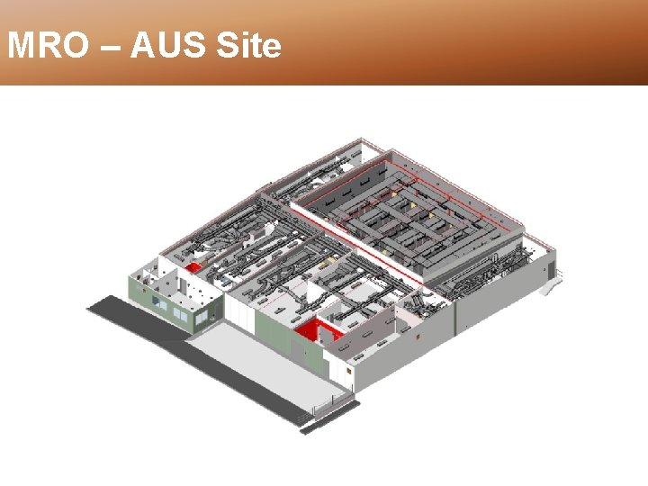
MRO – AUS Site
MRO – AUS Site
MRO – AUS Site
MRO – AUS Site
MRO – AUS Site
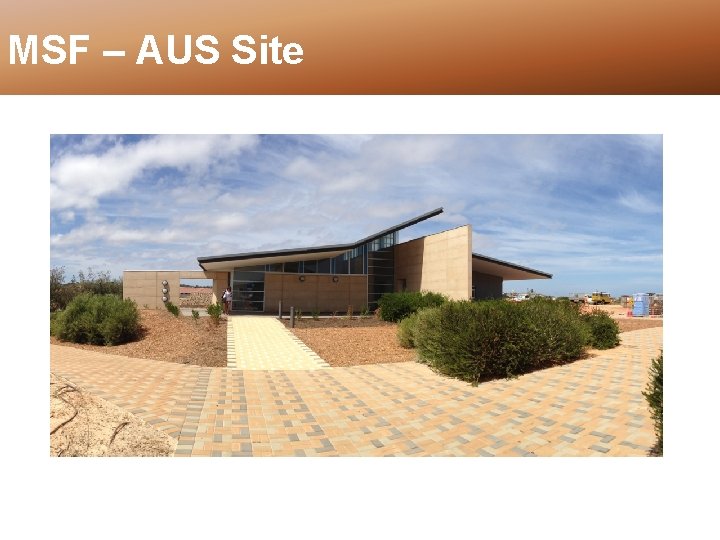
MSF – AUS Site
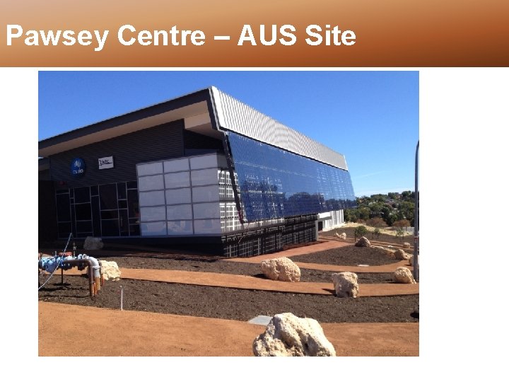
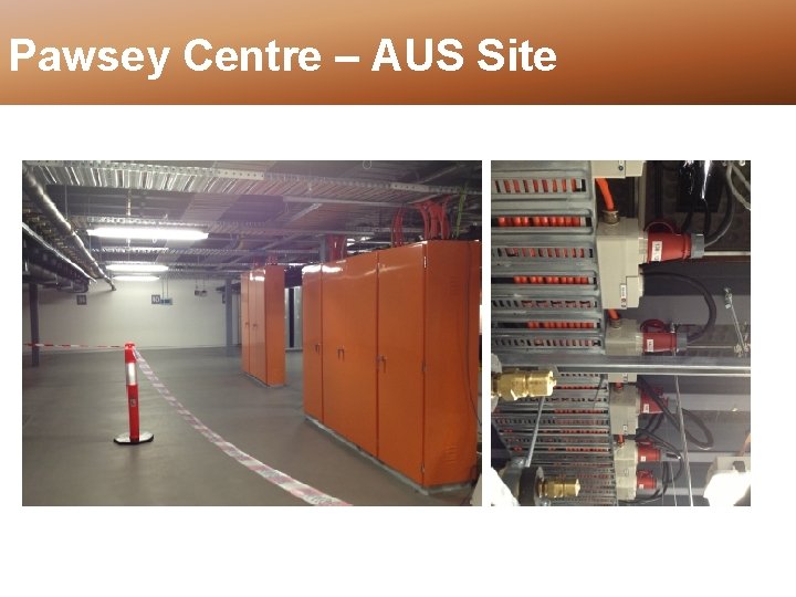
Pawsey Centre – AUS Site
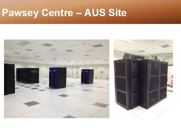
Pawsey Centre – AUS Site
Pawsey Centre – AUS Site