
SIS UML DIAGRAMS PREPARED FOR IT315 AT SNHU

- Slides: 7
SIS UML DIAGRAMS PREPARED FOR IT-315 AT SNHU BY ANN-KATHERINE JOHNSON
This presentation highlights the analysis of a complex SUMMARY computing problem using UML diagrams to model the system and explore the relationships between the functional, structural, and behavioral aspects of the system.
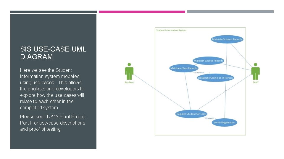
SIS USE-CASE UML DIAGRAM Here we see the Student Information system modeled using use-cases. This allows the analysts and developers to explore how the use-cases will relate to each other in the completed system. Please see IT-315 Final Project Part I for use-case descriptions and proof of testing.
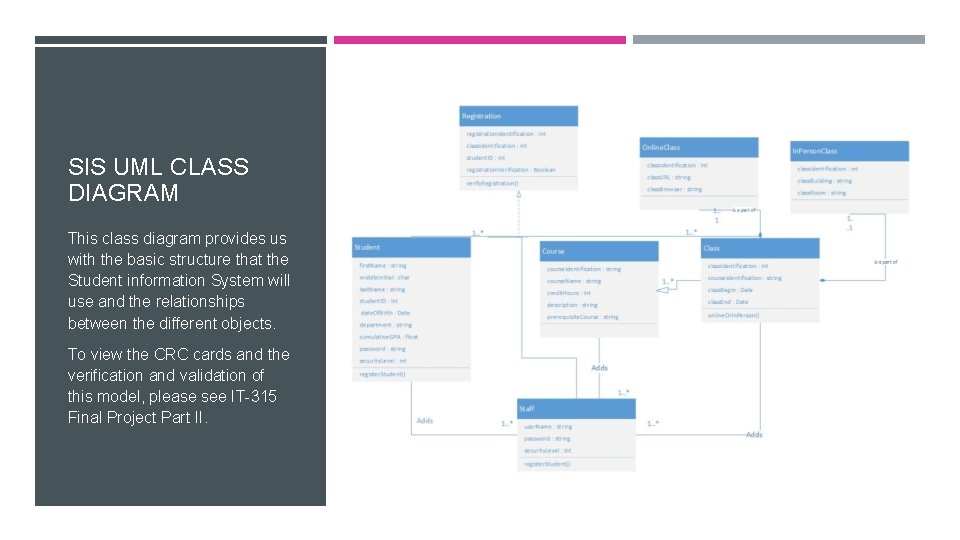
SIS UML CLASS DIAGRAM This class diagram provides us with the basic structure that the Student information System will use and the relationships between the different objects. To view the CRC cards and the verification and validation of this model, please see IT-315 Final Project Part II.
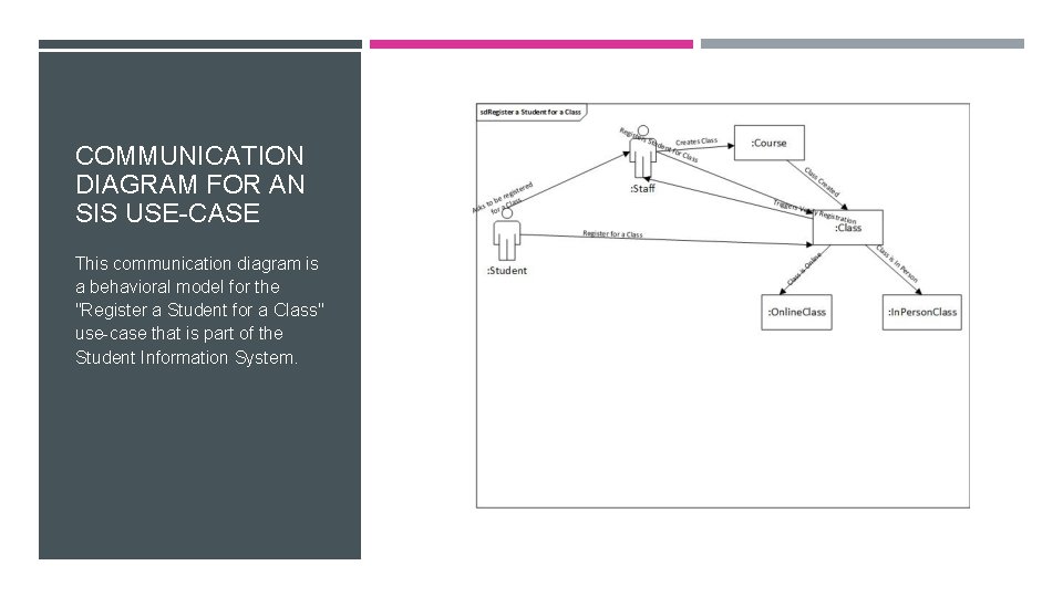
COMMUNICATION DIAGRAM FOR AN SIS USE-CASE This communication diagram is a behavioral model for the "Register a Student for a Class" use-case that is part of the Student Information System.
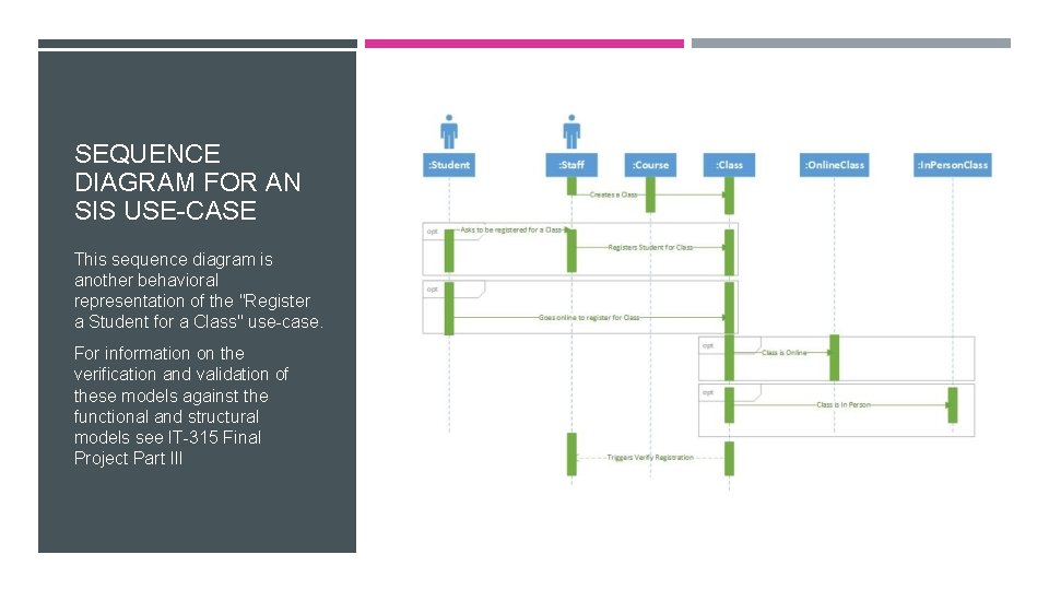
SEQUENCE DIAGRAM FOR AN SIS USE-CASE This sequence diagram is another behavioral representation of the "Register a Student for a Class" use-case. For information on the verification and validation of these models against the functional and structural models see IT-315 Final Project Part III
These models demonstrate the modeling of the SUMMARY functional, structural and behavioral aspects of a computer system. Modeling all of these aspects gives designers and developers a better understanding of how the components of the system will need to work together before programing is begun. Using these UML processes increase the likelihood that the finished system meets the business needs.